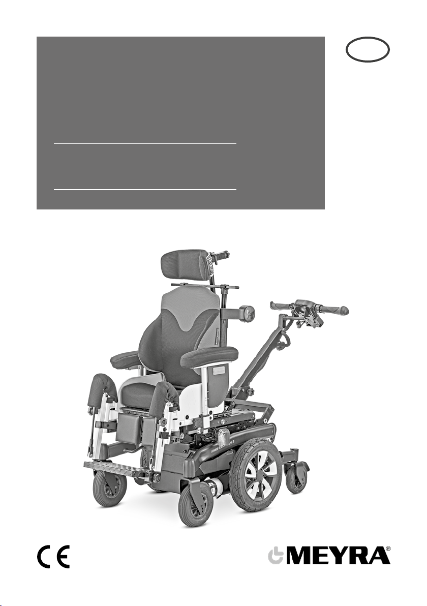
Meyra iChair DYNAMIC 1.623 User manual

en
Operating manual
Electric wheelchair
Model 1.623

2
Contents
Meaning of the applied markers 7
Introduction 7
List of models 7
Indications / contraindications 7
Acceptance 8
Intended purpose 8
Target group 8
Use 9
Adjustment 9
Combination with manufacturer foreign products 10
Reinstallment 10
Life span 10
Base position 10
Overview 11
Model 1.623 11
Driving module 13
Adjustment module 13
Handling the electric wheelchair 14
Securing the electric wheelchair 14
Functional checks 14
Driving 14
Brakes 14
Service brake 14
Braking down the wheelchair 14
Emergency braking 14
Parking brake 14
Locking the brakes 15
Releasing the brakes 15
Drive-/push mode 16
Selecting the push mode 16
Selecting the motor mode 16

3
Driving module 17
Switching on the driving module 17
Battery charging socket 17
Battery voltage 18
Battery gauge 18
Evaluation 18
Preselectable maximum speed 19
Preselect the maximum speed 19
Diving speed stages 19
Drive and steering movement 20
Braking the electric wheelchair 20
One-hand operation 20
Keys and symbols - driving module 21
Keys and symbols - adjustment module 22
Selecting the operation 23
Pre-operation checks 24
Battery charging procedure 25
Positioning the steering unit 26
Function description 26
Adjusting the height of the steering unit 26
Adjusting the angle of the steering rod 26
Adjusting the angle of the steering unit 27
Setting the step length of the accompanying person 27
Arm supports 28
Adjusting the height of the arm supports 28
Back support 29
Locking the back support 29
Releasing the back support 29
Back support upholstery 30
Removing the back support upholstery 30
Adjusting the adjustable back 30
Placing the back support upholstery 30

4
Head support 31
Adjustment of the head support 31
Adjusting the head support to the head posture 31
Removing and height adjusting the head support 31
Adjusting the head support during handicapped transport inside a motor vehicle 31
Leg support 32
Height adjustment of the leg support 32
Footboard 32
Folding the footboard up 33
Folding the footboard down 33
Removing the leg support 34
Attaching the leg supports 34
Seat 35
Special safety information 35
Seat pad 35
Seat inclination 35
Electrically adjusting the seat angle 35
Seat height adjustment 36
Shoulder strap 37
Fastening the shoulder strap 37
Adjustment of belt length 37
Adjusting the shoulder strap to the body 38
Lighting 38
Loading and transportation 39
Loading 39
Ramps and lifting platforms 39
Transport of people inside a motor vehicle 39
Transport security 40
Tyres 41

5
Maintenance 41
Maintenance 41
Maintenance schedule 42
Fuses 44
Replacing the fuses 44
Lighting 45
Headlights 45
Fault correction 46
Basic safety information 47
Accompanying person 47
Special driving situations 47
Transfer out of the electric wheelchair 48
Reaching for objects 48
Driving on falling, rising or transverse gradients 48
Crossing obstacles 49
Electrical system 49
Transport in public methods of transportation 49
Driving on public highways 50
Cleaning 50
Finish 51
Disinfection 51
Repairs 51
Repairs 51
Customer Service 51
Spare parts 51
Information for extended pauses of use 52
Disposal 52

6
Technical data 53
Tyre pressure of pneumatic tyres 53
Maximum range 53
Hill climbing ability 54
Applied norms 54
Values acc. to ISO 7176-15 for model 1.623 iCHAIR Dynamic 55
Further technical data for model 1.623 iCHAIR Dynamic 56
Meaning of the labels on the electric wheelchair 58
Meaning of the symbols on the washing instruction 59
Meaning of the symbols on the type plate 60
Inspection certificate 61
Warranty / Guarantee 62
Warrantee / Guarantee section 63
Inspection certificate for transfer 63

7
MEANING OF THE AP-
PLIED MARKERS
Safety instructions with a coloured back-
ground are mandatory and need to be
observed under any circumstance!
☞This symbol indicates tips and recom-
mendations.
[ ] Reference to a picture number.
( ) Reference to a function element within
a picture.
Reference to a jamming area within a
picture.
INTRODUCTION
Read and observe this manual before first
operation.
Children and juveniles should read this
documentation together with their par-
ents respectively a supervisor or accom-
panying person before first use.
The present operating manual should help
you as well as the controlling person (ac-
companying person), to get accustomed to
the handling of your electric wheelchair as
well as to prevent accidents.
☞Please note that the illustrated equip-
ment variants can deviate from your
model.
We have therefore also listed chapters with
options that might not be applicable for
your individual electric wheelchair. A list of
the available options and accessories can
be viewed in the order form of your electric
wheelchair.
Users with visual impairments can find the
PDF-files together with further information
on our website:
< www.meyra.com >.
☞Contact your specialist dealer when re-
quired.
Alternatively users with visual impairments
can have the documentation read out by a
helper.
Inform yourself regularly about product
safety and possible recalls of our products
in the < Information center > on our website:
< www.meyra.com >.
We have developed an electric wheelchair
that complies with the technical and gov-
ernmental regulations of medical devices.
For information about a severe accident
that can still not be ruled out completely,
please use our E-mail address < info@mey-
ra.de > and inform the responsible govern-
mental agency of your country.
LIST OF MODELS
This operating manual applies to the follow-
ing models:
Model 1.623
INDICATIONS /
CONTRAINDICATIONS
In case of allergic reactions, skin rashes
and/or pressure sores during the use of
the electric wheelchair sores contact a
doctor immediately.
In order to prevent contact allergies, we
recommend to use the electric wheel-
chair only when wearing clothes.
The functional diversity of the electric
wheelchair permits application in cases
where extreme spasms and contractions of
the skeletal muscles lead to contortions, un-
controlled movements, slipping away and
functional losses as well as substantially to
completely pronounced impairment of the
mobility/walking in cases of structural and/

8
or functional damages to the lower extrem-
ities, such as amputations, results of injury,
musculoskeletal/neuromuskuloskeletally
caused motion disabilities e. g. through:
– paralysis,
– loss of limbs (leg amputation),
– defective/deformed limbs,
– joint contractures/-damages,
– other diseases.
– spasms.
Also to be observed for individual provision
are the physical and psychological state,
age of the user as well as the personal living
condition and private environment.
This is meant for the user of the electric
wheelchair as well as the accompanying
person controlling the electric wheelchair.
Every provision, case by case should be
checked, tested and aligned to the indi-
vidual ability limitations caused by the de-
fined disability through an educated person
(medical device consultant, rehabilitation
consultant u.o.). This also includes that
people that show a counter indications to
the named problems in some cases need
to give proof of the cognitive, mental and
moral ability to operate the electric wheel-
chair.
The electric wheelchair may not be used in
cases of:
– Influence of impairing medications to
the accompanying person (ask your
doctor or pharmacist).
– Extreme balance and/or perceptual
disorders of the accompanying person
(ask your doctor or pharmacist).
– Inability to sit.
– Accompanying persons that are physi-
cally or psychologically not able to steer
an electric wheelchair.
☞To these and other possible risk
concerning your electric wheelchair
ask your doctor, therapist or special-
ist dealer.
ACCEPTANCE
All products are checked for faults in the
factory and packed in special boxes.
☞However, we request that you check
the electric wheelchair for possible
transport damage immediately on re-
ceipt – preferably in the presence of the
carrier.
☞The packaging of the electric wheel-
chair should be stored for a further
transport that might become neces-
sary.
INTENDED PURPOSE
The electric wheelchair serves to improve
independent mobility in- and outdoors.
TARGET GROUP
The target group of the electric wheelchair
includes those groups of people that do
not have sufficient independent mobility
at their disposal, to move around inde-
pendently in- and outdoors.

9
USE
Never use the electric wheelchair without
the leg supports and arm support units
mounted!
The electric wheelchair serves solely for
transporting one sitting person. – Other
pulling or transporting uses do not com-
ply with its intended purpose.
The electric wheelchair is applicable on lev-
el, firm surfaces and can be used as follows:
– for indoors (e.g. apartment, day care),
– outdoors (e.g. paved paths in parks).
– Never expose the electric wheelchair to
extreme temperatures and damaging
environmental conditions, such as sun-
light, extreme cold or salty water.
– Sand and other dirt particles can seize
on moving parts and render them with-
out function.
The electric wheelchair offers manifold ad-
justment possibilities to individual vital sta-
tistics.
National regulations might prevent the use
on busses, trains or in aircraft.
☞Inform yourself at the transportation
companies concerning limitations.
☞Before going on a flight clarify the spe-
cific transport conditions with your
flight agency and also the legal regula-
tions concerning transport in a plane in
your country of residence as well as at
your destination.
Only apply the electric wheelchair within
the scope of the specifications and limita-
tion described in chapter Technical data on
page 53.
ADJUSTMENT
Always have adaptation, adjustment or re-
pair work carried out by a specialist dealer.
The electric wheelchair offers manifold ad-
justment possibilities to individual vital sta-
tistics. Before first use an adaptation of the
electric wheelchair and a practical instruc-
tion in the functionalities of your electric
wheelchair should be carried out by your
specialist dealer. The adaptation will take
into account the driving experience, the
physical limits of the user and the main
place of use of the electric wheelchair. Be-
fore first use, check the functionality of your
electric wheelchair.
Should your specialist dealer carry out a
revision/reconditioning or make funda-
mental changes to your electric wheelchair,
without the use of original spare parts, this
under certain conditions may result in a re-
marketing of your electric wheelchair. This
will further entail that your specialist dealer
might need to conduct new conformity as-
sessments and tests.
☞We recommend a regular inspection
of the electric wheelchair adjustment
in order to ensure a long-term optimal
provision even with changing illness/
handicap patterns of the user. Especial-
ly for juveniles an adjustment every 6
months is recommendable.
☞We recommend regular medical exam-
inations for independent determination
of the user ability.

10
COMBINATION WITH MAN-
UFACTURER FOREIGN
PRODUCTS
Any combination of your electric wheelchair
with components not supplied by us gener-
ally results in an amendment to your electric
wheelchair. Please inquire with us if there is
a valid combination clearance/release.
REINSTALLMENT
The electric wheelchair is suited for reinstall-
ment. With the building block system the
electric wheelchair can be fit to accommo-
date different handicaps body sizes. Before
reimplementation the electric wheelchair is
to undergo a complete inspection.
☞Hygienical measures required for rein-
stallment are to be carried out accord-
ing to a validated hygienic plan and
must include disinfection.
The service manual, intended for the spe-
cialist dealer provides information to the re-
installment and reinstallment frequency of
your electric wheelchair.
LIFE SPAN
We expect an average life span of about
5 years for this product, as far as the product
is applied for its designated purpose and all
maintenance and service guidelines. The life
span of your product depends upon the fre-
quency of use, the application environment
and care. The implementation of spare parts
can prolong the life span of the product. As
a rule spare parts are available up to 5 years
after production is discontinued.
☞The indicated lifespan does not consti-
tute additional guarantee.
BASE POSITION
Only drive on slopes, inclines and ob-
stacles in the basic position of the seat
height adjustment and the seat inclina-
tion. – Danger of overturning!
Basic position is to be understood as:
– Seat height adjustment in the lowest
position.
– Seat inclination in horizontal position
(but max 10°).

1 2 3
4
5
6
7
8
910
11
OVERVIEW
Model 1.623
The overview shows the most important components and operating devices of the electric
wheelchair.
Pos. Description
(1) Head support
(2) Back support
(3) Arm support
(4) Seat pad
(5) Leg support
(6) Calf pads
(7) Footboard
(8) Type plate
(9) Selection lever drive-/push mode
(10) Front lighting

11
121314
17
16
21
22
18
19
20
2324
15
12
(11) Steering wheel
(12) Driving wheel
(13) Rear lighting
(14) Battery charging socket
(15) Support castor
(16) Angle adjustment of the push bar
(17) Push bar
(18) Height adjustment of the push bar
(19) Steering unit
(20) Driving module
(21) Driving lever forward
(22) Adjustment module
(23) Driving lever backwards
(24) Handle bar
Pos. Description

11 12
21 3 4 5
678910
13
14
13
Driving module
Pos. Description
(1) Key On/Off
– Switches the electric wheelchair on/
off.
(2) LED-display right turn signal / lighting /
warning signal
– Prolonged pressing of the key (8)
switches the lighting on/off.
(3) Control display of the battery charging
condition / the speed setting
(4) LED-display direction reverse
– Pressing of the key (4) switches the
direction reverse on/off.
(5) Key speed setting
– First short key activation (< 1 s)
shows the speed setting (3).
– Each further short pressing of the
key switches the setting to the next
higher setting.
(6) Key direction reverse
(7) Signal tone (horn)
– When pressing this key a horn signal
sounds.
(8) Right indicator
(9) Left indicator
(10) LED-display left turn signal / lighting /
warning signal
– Prolonged pressing of the key (9)
switches the warning signal on/off.
Adjustment module
Pos. Description
(11) Adjustment seat inclination
(12) Adjustment seat height
(13) Key adjustment negative
– Adjustment drives into the basic po-
sition on activation of the key.
(14) Key adjustment positive
– Adjustment drives from the basic
position on activation of the key.

14
HANDLING THE ELECTRIC
WHEELCHAIR
Securing the electric wheelchair
The electric wheelchair is to be secured as
follows to prevent it from rolling off unin-
tentionally:
1. Switch the selection lever for drive-/
push mode up to drive mode on both
sides.
2. Switch off the operating module.
Functional checks
The functions and safety of the electric
wheelchair must be checked before the
start of each journey.
☞Therefore observe chapter Pre-opera-
tion checks on page 24.
Driving
Speed and driving direction is determined
by the movement of the driving lever and
handle bar as well as the selected speed
setting of your electric wheelchair.
BRAKES
Brake the vehicle down carefully and in
time. This is especially the case when driv-
ing in front of people and while driving
downhill!
Service brake
The motors work electrically as operating
brake and carefully brake the electric wheel-
chair down without jerks to stillstand.
Braking down the wheelchair
For allotted braking of the electric wheel-
chair slowly guide the driving lever back to
the centre position (zero-setting).
Emergency braking
☞The electric wheelchair stops in short-
est distance after releasing the driving
lever.
Parking brake
The parking brakes are only effective when
the selection lever drive-/push mode is set
to drive mode on both drives.
☞The parking brake disengages auto-
matically when you start to drive.
The parking brakes are manually disen-
gaged by switching the selection lever
drive-/push mode on both drives to push
mode.

1
2
15
Locking the brakes
It should not be possible to push the elec-
tric wheelchair forward when the brakes
are engaged.
To engage the brakes swivel the selection
lever drive-/push mode on both sides as far
as possible into drive mode [1].
☞Activation of the selection levers are
intended for an accompanying person.
Releasing the brakes
Only transfer into or out of the electric
wheelchair when the electric wheelchair
is switched off and the selection lever
drive-/push mode on both sides is in drive
mode!
Inadvertently knocking the driving lever
will set the electric wheelchair in motion
without control! – Danger of accidents!
To loosen the brakes swivel the selection le-
ver drive-/push mode on both sides down
as far as possible into push mode [2].
☞Activation of the selection levers are
intended for an accompanying person.

2
1
16
Drive-/push mode
Only switch the electric wheelchair to
push mode when it is standing still for
positioning or in case of emergencies, but
not on slopes/hills.
After push mode do not forget to switch
the drive back to drive mode. Danger of
uncontrolled electric wheelchair move-
ment if you do not do this.
☞For shunting the electric wheelchair,
grab the push bar.
Selecting the push mode
1. Switch off the operating module be-
cause the pushing will otherwise be
made difficult by the electric system.
☞Therefore observe chapter Driving
module on page 17.
2. Disengage the brakes [1].
☞Therefore observe chapter Releasing
the brakes on page 15.
☞The electric wheelchair can now be
pushed.
Selecting the motor mode
1. Activate the brakes [2].
☞Therefore observe chapter Releasing
the brakes on page 15.
2. Switch the driving module on.
☞Therefore observe chapter Switching
on the driving module on page 17.
The electric wheelchair is now ready for use
again.

53
1 2
6
4
17
DRIVING MODULE
Switching on the driving module
Do not move the driving lever (3)+(5) or
handlebar during the system test.
Press the ON/OFF key (1) to switch on the
driving module. The electronic system now
performs a system test.
☞The electronic system is ready when
the battery gauge (2) is permanently lit.
☞After about 20 seconds stillstand, the
system switches into stand-by-mode
and the LED for reversing the driving
direction (4) blinks.
– To exit the stand-by-mode, press
and release one of the driving levers
(3) or (5).
Battery charging socket
Do not insert other objects into the bat-
tery charging socket. – Danger of short
circuit!
To charge the batteries first switch off the
driving module. Then insert the plug of the
battery charger into the charging socket (6).

1
18
Battery voltage
The battery indicator [1] displays the battery
voltage after the system test when the driv-
ing module has been switched on.
Less LED segments of the battery gauge are
lit as the battery voltage reduces.
Battery gauge
The battery gauge [1] displays the existing
battery voltage as follows:
The colours mean:
Green Batteries charged
☞The charging status corre-
sponds to the number of
green lit LEDs.
Yellow Recharging recommended.
Red Recharge batteries immedi-
ately.
☞An accurate battery indication is only
given during travel on a level surface.
☞Uphill/downhill driving can causes
an inaccurate indication.
Evaluation
The exactness of the battery gauge de-
pends for example on the temperature, age
and strain on the batteries is therefore sub-
ject to certain restrictions.
The kilometric performance (range) of
the electric wheelchair resp. the batteries
should be tested at least once.

2
1
19
Preselectable maximum speed
Danger of accident due to unsuitable set-
ting of the preselected speed!
After switching on the driving module, the
maximum speed setting will be the same as
that selected before switching off.
Preselect the maximum speed
By pressing the key [1] you switch between
the preselectable speed settings, 1for slow
to 5for fast.
The number of lit LEDs in the control gauge
[2] shows the selected speed setting.
Select a slow maximum speed (step 1) for
driving situations in which you do not feel
confident/safe (e.g. driving in confined
spaces, or similar).
☞The final speed is to be preselected in
dependence on the personal impres-
sion of the respective driving situation!
☞When driving on ramps, hills or slopes
the speed is to be adjusted to the in-
clination appropriately. Never exceed
the permitted max speed. – Danger of
accidents!
Diving speed stages
On the setting fast, the max. final speed of
the electric wheelchair is 5.5 km/h.
In speed limitation (slow) the maximum
speed of the electric wheelchair is 1.5 km/h.

1
32
5
6
4
20
Drive and steering movement
Only move the driving lever (2) or (3)
when the battery gauge [1] shows contin-
uous light.
With the driving lever (2) the electric wheel-
chair can be propelled forward and slowed
down to a stop.
With the driving lever (3) the electric wheel-
chair can be propelled backwards and
slowed down to a stop.
The further you move the driving lever
away from the centre position, the faster
the electric wheelchair will travel (up to the
preselected maximum speed).
The horizontal movements of the handle-
bar [4] effect curves. The wheelchair will
turn almost on the spot if the handlebar is
only deflected sideways.
☞The speed is reduced automatically
during reverse or curve driving.
Braking the electric wheelchair
The electric wheelchair stops when you re-
lease the depressed driving lever (2) or (3).
For allotted braking, slowly let the driving
lever return to zero-position.
One-hand operation
The driving direction is reversed by pressing
the key (5).
☞With active reversed driving direction,
the LED-display (6) lights up in orange.
Right driving lever for backwards, left
driving lever for forward.
☞In normal operation mode the LED-dis-
play (6) lights up in green. Right driving
lever for forward, left driving lever for
backwards.
Other manuals for iChair DYNAMIC 1.623
1
Table of contents
Other Meyra Wheelchair manuals

Meyra
Meyra 1.160 User manual

Meyra
Meyra 1.610 Manual

Meyra
Meyra 1.736 User manual

Meyra
Meyra Ortopedia iTravel 1.054 User manual

Meyra
Meyra 2.322 User manual

Meyra
Meyra 1.611 User manual

Meyra
Meyra 1.594 User manual

Meyra
Meyra 9.050 User manual

Meyra
Meyra 2.845 User manual

Meyra
Meyra 1.158 NANO C User manual

Meyra
Meyra PROFI 3 User manual

Meyra
Meyra X1 User manual

Meyra
Meyra 1.618 User manual

Meyra
Meyra 1.595-603 User manual

Meyra
Meyra RUNNER 1.445 User manual

Meyra
Meyra FX One 1.150 User manual

Meyra
Meyra 1.7 series User manual

Meyra
Meyra 1.620 User manual

Meyra
Meyra Optimus 2 User manual

Meyra
Meyra 1.155 NANO User manual