Michel's MIC210 User manual

Rev: 19/September/2017
MIC210 Electric Farm Conversion Instructions
Note: Apply the supplied Dielectric Lubricant to all wire connections when each wire is hooked up. The Dielectric
Lubricant will help to prevent corrosion.
Step 1: Disassemble
With the tarp all the way open, make a note of the number of
wraps of the tension cable on the front pulley (A) and measure
the distance from the pulley to the tarp. Now you can loosen the
pulley and remove it from the roll tube.
Step 2: Electric Pivot Arm Guide
Procedure: The electric pivot arm guide (X) is an aluminum
angle with one end bent down. Place on the front of the box
against the top rail of the box with the bent end on the driver’s
side. The bent end should be so it is just under the square tubing
of the holdbacks (see below). Secure to the box with 1/4"x1" lag
screws. You may need to bend it more and shorten the length if
necessary.
Step 3: Roll tube Preparation
If the roll tube does not stick at least 4” past the front of the box you will need to cut the roll tube back and weld
the supplied roll tube extension into the front of the roll tube. The minimum length of the extension piece can be
5-1/2” to the weld. After the roll tube extension is welded in, cut the front of the roll-tube so it sticks 4" past the
front of the box.
Step 4: Reinstall the front bevel pulley in the same location and wraps as were noted previously in Step 1.
Rev: 19/September/2017
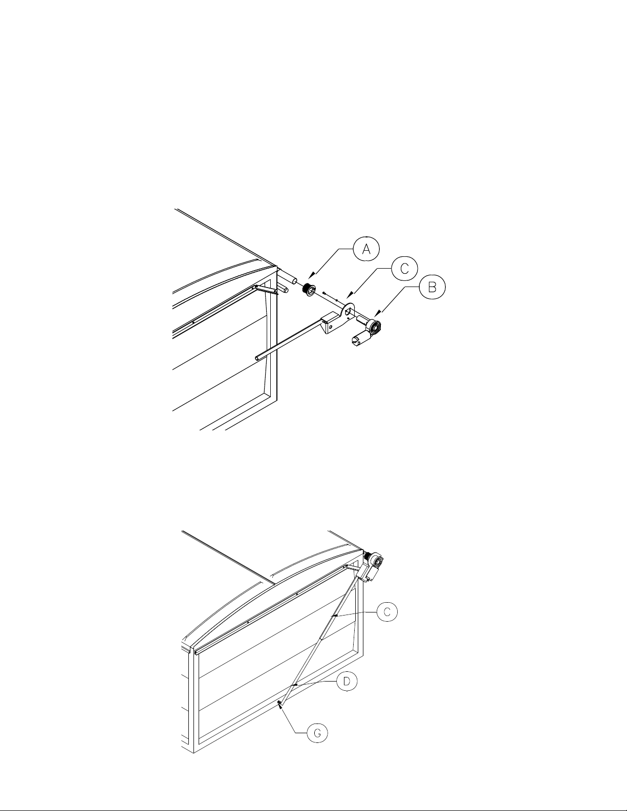
Step 5: Electric Motor Installation
Note: The front beveled cable pulley (A) is stamped FRONT STANDARD and the rear beveled pulley is stamped
FRONT REVERSE.
Procedure: Mount the motor (B) to the electric bracket (C) with 5/16"x3/4" hex bolts and lock washers as shown.
Slide the motor assembly into the front of the roll-tube and swing the arm down in-between the box and the cab.
Drill a 5/16" hole through the roll-tube and the predrilled hole in the motor shaft, approximately 1" from the
bracket. Secure together with a 5/16"x2-1/4" hex bolt and jam nut. The 1/4"x3/8" set screws in the front and rear
beveled pulleys are to be tightened in Step 10.
Step 6: Pivot Arm Installation
Procedure: To locate the pivot point on the front of the box, make a mark on the bottom sill of the box in the
middle of it. Note: Drill a 3/8" hole at pivot point (G) and slide the 1" round tubing (D) into the tubing on the
electric bracket (C). Secure the bottom tubing to the box with a 3/8"x4_1/2" hex bolt, 3/8" washers and nylon lock
nut.

Rev: 19/September/2017
Step 7.1: Rocker Switch Electrical Installation
Note:Apply the supplied Dielectric Lubricant to all wire connections when each wire is hooked up. The Dielectric
Lubricant will help to prevent corrosion.
Procedure: Mount the rocker switch in an obstruction free area inside the truck cab. Mount the solenoid on the
truck near the cab/batteries. Run the #6 double strand wire from the solenoid along the truck frame to the rear
box hinge point. Now run the wires along the box frame to the front box sill. Leave a slight amount of slack at
point (G) and continue running the wire along the pivot arm. Secure the wire to the top pivot arm (I) with the tie
straps provided. Attach the wire to the truck with the wire clips and 1/4"x1" self-tapping screws that are provided.
Connect the wires to the motor posts. The ends at the solenoid both get a black rubber boot and a #6-1/4" stud
crimped on.
Step 7.1: Rocker Switch Electrical Installation Cont.
Run the 14-3 wire from the solenoids to the rocker switch. At the switch each wire gets a 14G female end crimped
on and at the solenoid each wire gets a 14G female end except for the wire connected to the middle post of the
switch gets a 14G-1/4" ring terminal crimped on to connect to the positive post of the solenoid. Follow wiring
Schematic below, raise and lower the hoist to make sure that the wires are free from obstructions. Run #6 wire
from the solenoid to the battery posts. The wire with the red stripe will be the positive wire and will get bolted on
the positive post marked (+) along with the black 14Ga wire running from the switch. The black wire or negative
wire will be bolted onto the bottom negative post (-).Put the 50A circuit breaker in line with the positive wire.
Once everything is wired secure the motor cover to the motor with the 2 self-tapping screws provided.
ROCKER SWITCH
50AMP
CICUIT BREAKER
HEAVY DUTY REVERSE
DC CONTACTOR
BATTERY
NEGATIVE (-)
BATTERY
POSITIVE (+)
WIRE LEADS
TO MOTOR
Rev: 19/September/2017
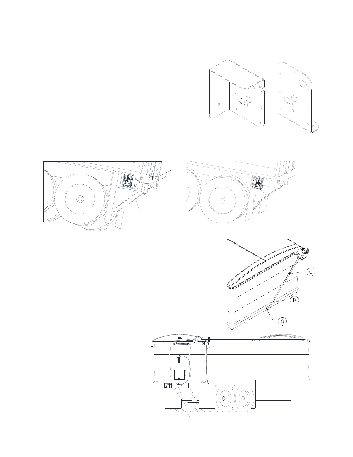
Step 7.1.1: MIC210 Control Box Installation
Depending on the grain box, two different mounting brackets may
be used. If the grain box already has a large ‘U’-shaped bracket
which houses air controls, use the basic plate. If not equipped with
this ‘U’ –shaped bracket then the shielded bracket which mounts to
the back side of the mud flap bracket should be used. The MIC210
Control Box mounting plate will be mounted to the box using the
3/8” bolts provided. Wire in the power wire and the electric tarp
motor wires (if applicable) before securing the MIC210 Control Box
to the mounting plate.
Step 7.1.2: Wiring the MIC210 System on a grain truck equipped
with an electric tarp
Run 6 AWG wire from the battery underneath the truck, along the frame to
the MIC210 control box. Make sure the inline circuit breaker is connected to
the positive wire near the battery, but do not connect to the battery until
all wire ends are connected correctly to refrain from shorting anything out.
Once the wires are installed and secured to the truck, thread the wires
through the appropriate hole (described below) of the mounting plate
coming in from behind the plate. Remove the punch outs with a chisel and
hammer. Place a grommet in each of the slots to protect the wires. Run the
#6 double strand wire from the MIC210 box
along the truck frame to the rear box hinge
point. Now run the wires along the box
frame to the front box sill. Leave a slight
amount of slack at point (G) and continue
running the wire along the pivot arm.
Secure the wire to the top pivot arm (I) with
the tie straps provided. Attach the wire to
the truck with the wire clips and 1/4"x1"
self-tapping screws that are provided.
MIC210 MOUNTED
TO BRACKET
SHIELDED MUD FLAP
BRACKET MOUNT
BOLTED TO STEEL
MUD FLAP MOUNT
PUNCH
OUTS
Shielded Mud Flap Bracket Mount
PUNCH
OUTS
Basic Plate
BASIC MOUNTING
PLATE
U-SHAPED
BRACKET
WIRES THROUGH HOLE
IN THE FRAME
TARP WIRE

Rev: 19/September/2017
Connect the wires to the motor posts. The ends at the MIC210 box and the motor all get a #6-1/4" stud crimped
on. These motor wires thread through the middle hole on the mounting plate. The incoming power wires thread
through the bottom hole of the bracket. Make sure the grommets have been installed to protect the wire. The
third hole at the top of the bracket is for the hoist and the Power Pro leads. Slide them into the top hole using the
slot. The third grommet will need to be split using a pair of side cutters or a knife. Wrap the split grommet around
the actuator and hoist leads. Then insert it into the top hole. Next, connect the power wires to the solenoid. The
positive wire goes on the positive post (top left) of the solenoid. The negative wire goes on the negative post (top
right) of the solenoid. Then, connect the tarp motor wires to the solenoid. These wires connect to the remaining
bottom posts on the solenoid. It does not matter which wire goes where on these two posts. If they end up being
backwards to the remote there is a very simple setting in the remote which can reverse them without having to
physically switch the wires. Please see the R200 Remote instruction manual, Section 4.2.2. There is a specific way
in which the 6 AWG wires must be positioned in order to fit inside the MIC210 Control Box. Please refer to the
Diagram on the next page. Once all the wires are connected to the MIC210 box connect the wires to the battery to
ensure everything works before carrying on to securing the box to the mounting plate.
POWER
NEGATIVE
TARP WIRE
RUN THIS WIRE
ON THE OUTSIDE
OF THE BUMP
POWER
POSITIVE
TARP WIRE
RUN THESE THREE
WIRES ON THE
INSIDE OF THE BUMP
CIRCUIT BREAKER
TO MOTOR
FROM BAT (-)
TO MOTOR
FROM BAT (+)
Rev: 19/September/2017
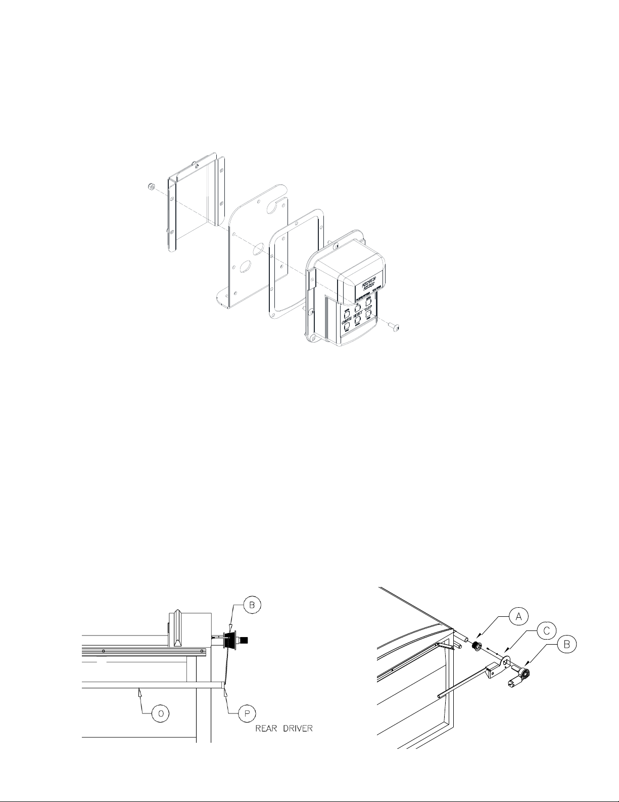
Securing MIC210 Control box to Mounting Plate
Start by mounting the control box and gasket to the mounting plate by using the bottom two holes in the control
box, this will aid in holding everything in place before you install the back cover. Next make sure your wires are still
remaining in the correct positions according to the diagram to refrain from pinching anything, install the back
protective cover using the remaining five holes in the control box.
Step 8: Beveled Cable Pulley Installation & Tension Control Adjustment
Procedure: Roll the tarp to the open position.
1. Installing cable onto rear beveled pulley:
Pull the cable from the rear holdback system (O) towards the rear beveled pulley stamped FRONT REVERSE (B).
Insert cable end into pulley slot and rotate beveled pulley 1-3/4 turns for an 8-1/2ft box or 2-1/4 turns for an 8ft
box. Rotate the pulley from the underside of it on the large diameter. Properly position the beveled pulley on the
roll-tube so that the nylon cable- guide (P) on the holdback lines up with the small diameter on the pulley. Tighten
the 1/4"x3/8" set screws (B) to hold the pulley in place.
2. Installing cable onto front beveled pulley:
Pull the cable from the front holdback system towards the front beveled pulley stamped FRONT STANDARD (A).
Repeat the rear beveled pulley procedure. Roll the tarp open and closed several times checking each time to make
sure that the cable follows in the pulley grooves and the tarp rolls evenly. If the cable does not follow in the
grooves, move the beveled pulley in or out until the correct position is achieved. If the tarp does not roll evenly,
roll the tarp to the open position; loosen the 1/4"x3/8" set screws in the front and rear pulleys and increase the
wrap. This will increase the tension. Do not allow the pulley to have less than one complete wrap of cable when
the tarp is in the open position.

Rev: 19/September/2017
Optional Manual Override
Step 1: Remove the motor cover and disconnect the motor from the power supply.
Step 2: Remove the plastic cap covering the manual input shaft. Do not use the manual override when the motor
is running or the motor is connected to the power supply.
Step 3: Using a 1/2in socket and a speed ratchet or impact driver, simply slide onto the manual input shaft and
drive the gearbox as needed. Keep in mind that 90 revolutions of input will result in one revolution of output.
Step 4: Remove the driver and re-install the plastic cap.
Warranty
Michel's Industries warrants their products for a period of one year from date of purchase. Any parts returned to
Michel's Industries LTD. will be shipped prepaid by the customer and will be returned F.O.B. St. Gregor, Sk. Canada.
We will not assume responsibility for shipping, labor or travel expenses. Please Note: We reserve the right to
make improvements; therefore specifications are subject to change without notice.
Note: If wiring is hooked up incorrectly it will void your warranty.
The enclosed device complies with Part 15 of the FCC Rules. Operation is subject to the following two conditions: (i.) this device may not cause
harmful interference and (ii.) this device must accept any interference received, including interference that may cause undesired operation.
Contains FCC ID: MCQ-XB900HP
Contains IC: 1846A-XB900HP
NOTE: This equipment has been tested and found to comply with the limits for a Class A digital device, pursuant to part 15 of the FCC Rules.
These limits are designed to provide reasonable protection against harmful interference when the equipment is operated in a commercial
environment. This equipment generates, uses, and can radiate radio frequency energy and, if not installed and used in accordance with the
instruction manual, may cause harmful interference to radio communications. Operation of this equipment in a residential area is likely to cause
harmful interference in which case the user will be required to correct the interference at his own expense.
***For Remote Operation and Programming functions refer to the R200 Remote
Instruction Manual Section 8.0.0***

Rev: 19/September/2017
Michel's Industries LTD.
P.O. Box 119
St. Gregor, SK S0K 3X0
CANADA
TEL: (306) 366-2184 FAX: (306) 366-2145
www.michels.ca
Other manuals for MIC210
1
Table of contents
Other Michel's Farm Equipment manuals


Popular Farm Equipment manuals by other brands


aivituvin
aivituvin AIR 18 instruction manual

AGCO
AGCO Cumberland Flex-Flo 220 installation manual

Sly France
Sly France BOSS Series operating instructions

FARMTECH
FARMTECH T-DCBM-4 user manual

Nutriculture
Nutriculture Amazon Aeroponic System Assembly and operating instruction

Toro
Toro 41614 installation instructions

GREAT PLAINS
GREAT PLAINS Ultra-Till I 3030 Series Operator's manual

pronovost
pronovost SilaTube P-6500 Operator and parts manual

Killbros
Killbros 575 Operator's Manual/Parts Catalog

BOXER
BOXER SB user manual

Monosem
Monosem NG Plus 2 Operator's manual

Raven
Raven AutoBoom Case IH Patriot 250 installation manual