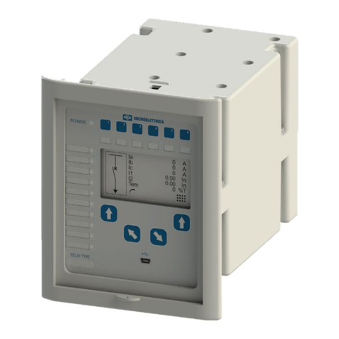
Microelettrica Scientifica MC20-CEI User manual

MC20-CEI
Doc. N°
MO-0431-ING
Microelettrica Scientifica S.p.A. - Copyright 2009 FW
1080.36.03.X Date
18.11.2011 Rev.
3
OVERCURRENT AND DIRECTIONAL EARTH FAULT
PROTECTION
ACCORDING TO CEI 0-16
TYPE
MC20-CEI
OPERATION MANUAL

MC20-CEI
Doc. N°
MO-0431-ING
Microelettrica Scientifica S.p.A. - Copyright 2009 FW
1080.36.03.X Date
18.11.2011
Rev.
3
Pag.
2of
35
1. General Utilization and Commissioning Directions____________________________________________________________________ 3
1.1 - Storage and Transportation_____________________________________________________________________________________ 3
1.2 - Installation __________________________________________________________________________________________________ 3
1.3 - Electrical Connection__________________________________________________________________________________________ 3
1.4 - Measuring Inputs and Power Supply______________________________________________________________________________3
1.5 - Outputs Loading _____________________________________________________________________________________________ 3
1.6 - Protection Earthing ___________________________________________________________________________________________ 3
1.7 - Setting and Calibration ________________________________________________________________________________________3
1.8 - Safety Protection_____________________________________________________________________________________________ 3
1.9 - Handling ___________________________________________________________________________________________________ 3
1.10 - Maintenance _______________________________________________________________________________________________ 4
1.11 - Waste Disposal of Electrical & Electronic Equipment ________________________________________________________________ 4
1.12 - Fault detection and repair _____________________________________________________________________________________4
2. General Characteristics___________________________________________________________________________________________ 5
2.1 - Power Supply _______________________________________________________________________________________________ 5
2.2 - Operation and Algorithms ______________________________________________________________________________________ 6
2.2.1 - Reference Input Values ____________________________________________________________________________________ 6
2.2.2 – Input quantities __________________________________________________________________________________________ 6
2.2.3 – Time Current Curves IEC (TU1029 Rev.0) ____________________________________________________________________8
2.2.4 - Time Current Curves IEEE (TU1028 Rev.0) ____________________________________________________________________ 9
2.2.5 - Funzioni (Functions and Settings) ___________________________________________________________________________ 10
3. Data Logger ___________________________________________________________________________________________________ 16
3.1 – Display ___________________________________________________________________________________________________ 16
3.2 – Export data stored __________________________________________________________________________________________ 17
4. Logic Blocking of Functions______________________________________________________________________________________ 18
4.1 – Blocking output_____________________________________________________________________________________________ 18
4.2 – Blocking Input______________________________________________________________________________________________ 18
5. Output Relays__________________________________________________________________________________________________ 18
6. Digital Inputs___________________________________________________________________________________________________ 19
7. Self-diagnostic _________________________________________________________________________________________________ 19
8. Relay Management______________________________________________________________________________________________ 20
9. Signalizations__________________________________________________________________________________________________ 21
10. Keyboard_____________________________________________________________________________________________________ 21
11. Serial Communication__________________________________________________________________________________________ 22
11.1 - Main RS485 Serial Communication Port_________________________________________________________________________ 22
11.2 - Communication Port on Front Face Panel _______________________________________________________________________23
12. Menu and Variables ____________________________________________________________________________________________ 24
12.1 - Misure in Tempo Reale (Real Time Measurements)________________________________________________________________24
12.2 – Misure (Instantaneous Measurements) _________________________________________________________________________ 24
12.3 – Cont.Int (Operation Counters) ________________________________________________________________________________ 24
12.4 – UltimiSc (Event Recording)___________________________________________________________________________________ 25
12.5 - Regolazioni (Programming / Reading the Relay Settings) ___________________________________________________________ 26
12.5.1 - NodoCom (Communication Address) _______________________________________________________________________ 26
12.5.2 – Data/Ora (Time/Date) ___________________________________________________________________________________ 26
12.5.3 – Val.Nom. (Rated Input Values) ____________________________________________________________________________26
12.5.4 – Funzioni (Functions) ____________________________________________________________________________________ 27
12.6 – Cfg.Relè (Relay Configuration)________________________________________________________________________________29
12.7 – Comandi (Commands) ______________________________________________________________________________________ 30
12.8 - Info&Ver (Firmware - Info&Version) ____________________________________________________________________________ 30
13. Keyboard Operational Diagram __________________________________________________________________________________ 31
14. Password ____________________________________________________________________________________________________ 32
14.1 - MS-Com Password _________________________________________________________________________________________ 32
15. Maintenance __________________________________________________________________________________________________ 32
16. Power Frequency Insulation Test_________________________________________________________________________________ 32
17. Wiring Diagram________________________________________________________________________________________________ 33
18. Overall Dimensions (mm) – Protection Degree IP44 (on request IP55) __________________________________________________ 33
19. Direction for PCB's Draw-Out and Plug-In__________________________________________________________________________ 34
19.1 - Draw-Out _________________________________________________________________________________________________ 34
19.2 - Plug-In ___________________________________________________________________________________________________ 34
20. Electrical Characteristics _______________________________________________________________________________________ 35

MC20-CEI
Doc. N°
MO-0431-ING
Microelettrica Scientifica S.p.A. - Copyright 2009 FW
1080.36.03.X Date
18.11.2011
Rev.
3
Pag.
3of
35
1. General Utilization and Commissioning Directions
Always make reference to the specific description of the product and to the Manufacturer's instruction.
Carefully observe the following warnings.
1.1 - Storage and Transportation
must comply with the environmental conditions stated on the product's instruction or by the applicable IEC
standards.
1.2 - Installation
must be properly made and in compliance with the operational ambient conditions stated by the Manufacturer.
1.3 - Electrical Connection
must be made strictly according to the wiring diagram supplied with the Product, to its electrical characteristics
and in compliance with the applicable standards particularly with reference to human safety.
1.4 - Measuring Inputs and Power Supply
carefully check that the value of input quantities and power supply voltage are proper and within the permissible
variation limits.
1.5 - Outputs Loading
must be compatible with their declared performance.
1.6 - Protection Earthing
When earthing is required, carefully check its effectiveness.
1.7 - Setting and Calibration
Carefully check the proper setting of the different functions according to the configuration of the protected system,
the safety regulations and the co-ordination with other equipment.
1.8 - Safety Protection
Carefully check that all safety means are correctly mounted, apply proper seals where required and periodically
check their integrity.
1.9 - Handling
Notwithstanding the highest practicable protection means used in designing M.S. electronic circuits, the electronic
components and semiconductor devices mounted on the modules can be seriously damaged by electrostatic
voltage discharge which can be experienced when handling the modules.
The damage caused by electrostatic discharge may not be immediately apparent but the design reliability and the
long life of the product will have been reduced. The electronic circuits reduced by M.S. are completely safe from
electrostatic discharge (8 KV IEC 255.22.2) when housed in their case; withdrawing the modules without proper
cautions expose them to the risk of damage.

MC20-CEI
Doc. N°
MO-0431-ING
Microelettrica Scientifica S.p.A. - Copyright 2009 FW
1080.36.03.X Date
18.11.2011
Rev.
3
Pag.
4of
35
a.
Before removing a module, ensure that you are at the same electrostatic potential as the equipment by
touching the case.
b.
Handle the module by its front-plate, frame, or edges of the printed circuit board. Avoid touching the electronic
components, printed circuit tracks or connectors.
c.
Do not pass the module to any person without first ensuring that you are both at the same electrostatic
potential. Shaking hands achieves equipotential.
d.
Place the module on an antistatic surface, or on a conducting surface which is at the same potential as
yourself.
e.
Store or transport the module in a conductive bag.
More information on safe working procedures for all electronic equipment can be found in BS5783 and
IEC 147-OF.
1.10 - Maintenance
Make reference to the instruction manual of the Manufacturer ; maintenance must be carried-out by specially
trained people and in strict conformity with the safety regulations.
1.11 - Waste Disposal of Electrical & Electronic Equipment
(Applicable throughout the European Union and other European countries with separate collection program).
This product should not be treated as household waste when you wish dispose of it. Instead, it should be handed
over to an applicable collection point for the recycling of electrical and electronic equipment.
By ensuring this product is disposed of correctly, you will help prevent potential negative consequence to the
environment and human health, which could otherwise be caused by inappropriate disposal of this product. The
recycling of materials will help to conserve natural resource.
1.12 - Fault detection and repair
Internal calibrations and components should not be altered or replaced.
For repair please ask the Manufacturer or its authorized Dealers.
Misapplication of the above warnings and instruction relieves the Manufacturer of any liability.

MC20-CEI
Doc. N°
MO-0431-ING
Microelettrica Scientifica S.p.A. - Copyright 2009 FW
1080.36.03.X Date
18.11.2011
Rev.
3
Pag.
5of
35
2. General Characteristics
The MC is a very innovative and versatile line of Protective Relays which takes advantage of the long and
successful experience coming from the M-Line.
The main features of the MC-Line relays are:
Compact draw-out execution for Flush Mounting or for assembly in 19” 3U chassis for 19” Rack systems.
User friendly front face with 2x8 characters LCD Display, four signal Leds, four keys for complete local
management and 9-pin socket for local RS232 serial communication.
Four user programmable Output Relays. On request one of the Output Relays can be replaced by a Can Bus port
for control of additional I/O modules.
Three optoisolated, self-powered Digital Inputs.
RS485 communication port (independent from the RS232 port on front panel)
Totally draw-out execution with automatic C.T. shorting device.
Input currents are supplied to 3 current transformers: - two measuring phase current - one measuring the earth
fault zero-sequence current.
Current inputs can be 1 or 5A, selection between 1A or 5A is made by movable jumpers provided on the Relay
card. (see Fig 1)
The Measuring Ranges of the different inputs
respectively are:
Phase Currents : (0.1-40)In
Neutral Current : (0.01-4)On
Make electric connection in conformity with the
diagram reported on relay's enclosure.
Check that input currents are same as reported on
the diagram and on the test certificate.
2.1 - Power Supply
The auxiliary power is supplied by a built-in module fully isolated an self-protected.
Two options are available:
24V(-20%) / 110V(+15%) a.c.
80V(-20%) / 220V(+15%) a.c.
a) -
b) -
24V(-20%) / 125V(+20%) d.c.
90V(-20%) / 250V(+20%) d.c.
Before energizing the unit check that supply voltage is within the allowed limits.

MC20-CEI
Doc. N°
MO-0431-ING
Microelettrica Scientifica S.p.A. - Copyright 2009 FW
1080.36.03.X Date
18.11.2011
Rev.
3
Pag.
6of
35
2.2 - Operation and Algorithms
2.2.1 - Reference Input Values
Display Description Setting Range Step Unit
In 300 A Reference primary current of the relay 1
- 9999
1 A
I1 300 A Rated Primary current of phase C.T. 1
- 9999
1 A
I2 5 A Rated Secondary current of phase C.T. 1
- 5
1/5 A
Io1 100 A Rated Primary current of the tore C.T. detecting earth fault
current. 1
- 9999
1 A
Io2 1 A Rated secondary current of the tore C.T. detecting earth fault
current. 1
- 1
- A
Vo1 10 kV Rated primary voltage of VT phase to neutral 0.05
- 500
0.01 kV
Vo2 100 V Rated secondary voltage of VT phase to neutral 50
- 115
0.01 V
Freq 50 Hz System rated frequency 50
- 60
10 Hz
2.2.2 – Input quantities
2.2.2.1 - Mains Frequency (Freq)
The relay can operate either in 50Hz or 60Hz systems.
The rated Mains Frequency “ Freq “ must be set accordingly.
2.2.2.2 – Phase Current inputs (I1)
The relay directly displays the r.m.s. value of the Phase Currents “ IA “, “ IB ”, “ IC ” flowing in the Primary of
the input Current Transformers and refers all its measurements to that value.
To make the relay properly working with any C.T., when programming the relay settings, input the value “I1“
of the primary current of the phase C.Ts
Only phase A and C currents are measured, whereas the current of the phase B is computed as vector
summation of the currents of the other two phases.
The algorithm is based on the following considerations coming from well-known vector relations among the
three-phase currents and the zero sequence current.
-
In any circumstance – currents balanced or not, sinusoidal or not – it is always true that:
(
)
0IIII1
0CBA
=+++
-When no Earth Fault exists (I
0
= 0)
(
)
(
)
CABCBA
III0III2 +=⇒=++
The earth fault protection element is independently supplied by the residual current coming either from the
residual connection of 3 system C.Ts. or from the core balance C.T.
If any Earth Fault is experienced (I
0
≠0) the Earth Fault Protection Element trips independently from the
phase current measuring elements.
If no Earth Fault is present (I
0
= 0), the equation (2) is valid, no matter if currents are balanced or not,
sinusoidal or not.
The third phase current is calculated, in real time, as vector summation of the other two-phase currents.
During Faults:
A)
Single phase to earth Fault Trip of the earth fault element directly measuring the Residual Current.
B)
Two Phase Fault
In any case one of the currents directly measured is involved, so the
relay trips correctly.
C)
Two Phase to Earth Fault Same as A + B
D)
Three Phase Fault All the three currents are correctly measured (in any case two directly).

MC20-CEI
Doc. N°
MO-0431-ING
Microelettrica Scientifica S.p.A. - Copyright 2009 FW
1080.36.03.X Date
18.11.2011
Rev.
3
Pag.
7of
35
2.2.2.3 – Earth Fault Current Input (Ion)
Same as for the Phase Currents, the relay directly displays the r.m.s. value of the Zero Sequence Residual
Current flowing at the Primary of the Current Transformers.
If the input to the Earth Fault element is supplied by the residual connection of the 3 phase C.Ts., we shall
set for the variable “ Io1 ” the same value as “ I1 ”.
If the input to the Earth Fault element is supplied by a separated Core Balance C.T., or by another CT, “ Io1 ”
value will be the Rated Primary Current of this C.T., normally different from “ I1 ”.
2.2.2.4 - Algorithm of the time current curves
The Time Current Curves are generally calculated with the following equation :
(1)
rS
a
TTKB
1
Is
IA
t(I) +⋅⋅⋅
+
−
where
t(I) =
Actual trip time delay when the input current equals “I”
Is =
Set minimum pick-up level
K =
T
s
= Set time delay: t(I) = T
s
when
tr = Operation time of the output relay on pick-up
The parameters “ A“ , “ B“ and “ a“, have different values for the different Time Current Curves.
Curve Name Curve Identifier A B a
IEC A Inverse A 0.14 0 0.02
IEC B Very Inverse B 13.5 0 1
IEC C Extremely Inverse C 80 0 2
IEEE Moderate Inverse MI 0.0104 0.0226 0.02
IEEE Short Inverse SI 0.00342 0.00262 0.02
IEEE Very Inverse VI 3.88 0.0963 2
IEEE Inverse I 5.95 0.18 2
IEEE Extremely Inverse EI 5.67 0.0352 2
The maximum measuring current is “40xIn” for phase elements and “4xOn” for the neutral elements.
1
a
B
110A
−
+
−
10
II
s
=

MC20-CEI
Doc. N°
MO-0431-ING
Microelettrica Scientifica S.p.A. - Copyright 2009 FW
1080.36.03.X Date
18.11.2011
Rev.
3
Pag.
8of
35
2.2.3 – Time Current Curves IEC (TU1029 Rev.0)

MC20-CEI
Doc. N°
MO-0431-ING
Microelettrica Scientifica S.p.A. - Copyright 2009 FW
1080.36.03.X Date
18.11.2011
Rev.
3
Pag.
9of
35
2.2.4 - Time Current Curves IEEE (TU1028 Rev.0)

MC20-CEI
Doc. N°
MO-0431-ING
Microelettrica Scientifica S.p.A. - Copyright 2009 FW
1080.36.03.X Date
18.11.2011
Rev.
3
Pag.
10 of
35
2.2.5 - Funzioni (Functions and Settings)
2.2.5.1 - I> – First overcurrent protection level
Stato
(Status)
→Abilit. [Disabl.(Disable) / Abilit.(Enable)]
Opzioni
(Options)
→TCC D [D / A / B / C / MI / VI / I / EI / SI ]
→BI Disab. [Disabl.(Disable) / Abilit.(Enable)]
Livelli
(Trip Level)
→I> 0.5 In (0.10 ÷4.00) step 0.01 In
Tempi
(Timer)
→tI> 1.00 s (0.05 ÷60.00) step 0.01 s
Stato
(Status)
: If disable the function is disactivated
TCC : Time current curves
D =
Independent Definite Time
A =
IEC A Inverse
B =
IEC B Very Inverse
C =
IEC C Extremely Inverse
MI =
IEEE Moderate Inverse Curve
VI =
IEEE Very Inverse Curve
I =
IEEE Inverse Curve
EI =
IEEE Extremely Inverse Curve
SI =
IEEE Short Inverse Curve
BI : Operation controlled by Blocking Digital Input
I> : Trip level (limited to 40 times In)
tI> : Trip time delay
2.2.5.2 - I>> - Second overcurrent protection level
Stato
(Status)
→Abilit. [Disabl.(Disable) / Abilit.(Enable)]
Opzioni
(Options)
→BI Disab. [Disabl.(Disable) / Abilit.(Enable)]
Livelli
(Trip Level)
→I>> 0.9 In (0.50 ÷40.00) step 0.01 In
Tempi
(Timer)
→tI>> 0.25 s (0.05 ÷60.00) step 0.01 s
Stato
(Status)
: If disable the function is disactivated
BI : Operation controlled by Blocking Digital Input
I>> : Trip level (limited to 40 times In)
tI>> : Trip time delay

MC20-CEI
Doc. N°
MO-0431-ING
Microelettrica Scientifica S.p.A. - Copyright 2009 FW
1080.36.03.X Date
18.11.2011
Rev.
3
Pag.
11 of
35
2.2.5.3 – I>>> - Third overcurrent protection level
Stato
(Status)
→Abilit. [Disabl.(Disable) / Abilit.(Enable)]
Opzioni
(Options)
→BI Disab. [Disabl.(Disable) / Abilit.(Enable)]
Livelli
(Trip Level)
→I>>> 2.00 In (0.50 ÷40.00) step 0.01 In
Tempi
(Timer)
→tI>>> 0.05 s (0.05 ÷60.00) step 0.01 s
Stato
(Status)
: If disable the function is disactivated
BI : Operation controlled by Blocking Digital Input
I>>> : Trip level (limited to 40 times In)
tI>>> : Trip time delay
2.2.5.5 - Io> - First Earth Fault protection level
Stato
(Status)
→Abilit. [Disabl.(Disable) / Abilit.(Enable)]
Opzioni
(Options)
→BI Disab. [Disabl.(Disable) / Abilit.(Enable)]
Livelli
(Trip Level)
→Io> 0.50 Ion (0.01 ÷4.00) step 0.01 Ion
Tempi
(Timer)
→tIo> 0.50 s (0.05 ÷60.00) step 0.01 s
Stato
(Status)
: If disable the function is disactivated
BI : Operation controlled by Blocking Digital Input
Io> : Trip level
tIo> : Trip time delay
2.2.5.6 - Io>> (2F51N) - Second Earth Fault protection level
Stato
(Status)
→Abilit. [Disabl.(Disable) / Abilit.(Enable)]
Opzioni
(Options)
→BI Disab. [Disabl.(Disable) / Abilit.(Enable)]
Livelli
(Trip Level)
→Io>> 0.90 Ion (0.01 ÷5.00) step 0.01 Ion
Tempi
(Timer)
→tIo>> 0.05 s (0.05 ÷60.00) step 0.01 s
Stato
(Status)
: If disable the function is disactivated
BI : Operation controlled by Blocking Digital Input
Io>> : Trip level
tIo>> : Trip time delay

MC20-CEI
Doc. N°
MO-0431-ING
Microelettrica Scientifica S.p.A. - Copyright 2009 FW
1080.36.03.X Date
18.11.2011
Rev.
3
Pag.
12 of
35
2.2.5.7 – 67S1 – First Directional Earth Fault protection level
Stato
(Status)
→Abilit. [Disabl.(Disable) / Abilit.(Enable)]
Opzioni
(Options)
→BI Disab. [Disabl.(Disable) / Abilit.(Enable)]
Livelli
(Trip Level)
→Io.1 1.00 % (1 ÷10) step 0.01 %
→Uo.1 3.50 % (1 ÷40) step 0.01 %
→aA.1 260 ° (0 ÷360) step 1 °
→aB.1 350 ° (0 ÷360) step 1 °
Tempi
(Timer)
→t67.1 1.00 s (0.05 ÷1.00) step 0.01 s
Stato
(Status)
: If disable the function is disactivated
BI : Operation controlled by Blocking Digital Input
Io.1 : Trip level
Uo.1 : Trip level
aA.1 : First angle trip sector
aB.1 : Second angle trip sector
t67.1 : Trip time delay
2.2.5.8 – 67S2 – Second Directional Earth Fault protection level
Stato
(Status)
→Abilit. [Disabl.(Disable) / Abilit.(Enable)]
Opzioni
(Options)
→BI Disab. [Disabl.(Disable) / Abilit.(Enable)]
Livelli
(Trip Level)
→Io.2 2.00 % (1 ÷10) step 0.01 %
→Uo.2 3.50 % (1 ÷40) step 0.01 %
→aA.2 100 ° (0 ÷360) step 1 °
→aB.2 280 ° (0 ÷360) step 1 °
Tempi
(Timer)
→t67.2 0.70 s (0.05 ÷1.00) step 0.01 s
Stato
(Status)
: If disable the function is disactivated
BI : Operation controlled by Blocking Digital Input
Io.2 : Trip level
Uo.2 : Trip level
aA.2 : First angle trip sector
aB.2 : Second angle trip sector
t67.2 : Trip time delay

MC20-CEI
Doc. N°
MO-0431-ING
Microelettrica Scientifica S.p.A. - Copyright 2009 FW
1080.36.03.X Date
18.11.2011
Rev.
3
Pag.
13 of
35
2.2.5.9 - I.R.F. - Internal Relay Failure
Stato
(Status)
→Non Disp. Non Disp. (No Parameters)
Opzioni
(Options)
→Opz NoScat. [NoScat (No Trip) / Scatto (Trip)]
Livelli
(Trip Level)
→Non Disp. Non Disp. (No Parameters)
Tempi
(Timer)
→Non Disp. Non Disp. (No Parameters)
Opz : The variable “ Opl “ can be programmed to trip the output relays same as the other
protection functions (OpI = TRIP), or to only operate the “ IRF “ signal led without
tripping the output relays (OpI = NoTRIP).
2.2.5.10 - AnIn– Circuit Breaker Failure (F51BF)
Stato
(Status)
→Abilit. [Disabl.(Disable) / Abilit.(Enable)]
Opzioni
(Options)
→TrR Rele1 Relay1 – Relay2 – Relay3
Livelli
(Trip Level)
→Non Disp. Non Disp. (No Parameters)
Tempi
(Timer)
→tBF 0.25 s (0.05 ÷0.75) step 0.01 s
→tInc 0.25 s (0.05 ÷5.00) step 0.01 s
Stato
(Status)
: If disable the function is disactivated
TrR : Output relay programmed for trip command to the Circuit Breaker
tBF : Trip time delay
tInc : C/B Discrepancy time
Operation: If after the time “tBF” from pick-up of the programmed relay “TrR” the current measured still
exceeds 5%In, the output relay associated to the “AnIn” function is operated (relay another than TrR).

MC20-CEI
Doc. N°
MO-0431-ING
Microelettrica Scientifica S.p.A. - Copyright 2009 FW
1080.36.03.X Date
18.11.2011
Rev.
3
Pag.
14 of
35
2.2.5.11 - TCS (Trip Circuit Supervision)
Stato
(Status)
→Abilit. [Disabl.(Disable) / Abilit.(Enable)]
Opzioni
(Options)
→Non Disp. Non Disp. (No Parameters)
Livelli
(Trip Level)
→Non Disp. Non Disp. (No Parameters)
Tempi
(Timer)
→tTCS 1 s (0.01 ÷50) step 0.01 s
Stato
(Status)
: If disable the function is disactivated
tTCS : Trip time delay
Operation:
The relay includes a complete Circuit Breaker Trip Circuit Supervision unit that is associated to the Contact
“13-12(+)”.
The supervision works when the C/B is closed and recognizes the Trip Circuit as sound as far as the current
flowing exceeds “1mA”.
In case of Trip Circuit Fault detection, the relay associated to “TCS” function trip, and the “Led Trip” is lit-on.
To have Supervision also with the C/B open one N/C contact (52b) from the C/B and an external resistor “R”
are needed.
[ ]
52
R
1mA
V
kΩR−≤
where R
52
= Trip Coil internal resistance [kΩ]
V= Trip Circuit Voltage
[
]
W
R
V
2P
2
R
⋅≥
Designe power of external resistance “R”.

MC20-CEI
Doc. N°
MO-0431-ING
Microelettrica Scientifica S.p.A. - Copyright 2009 FW
1080.36.03.X Date
18.11.2011
Rev.
3
Pag.
15 of
35
2.2.5.12 - LCD – Display and Buzzer operation
Stato
(Status)
→Non Disp. Non Disp. (No Parameters)
Opzioni
(Options)
→Bkl Auto [Auto / On]
Livelli
(Trip Level)
→Non Disp. Non Disp. (No Parameters)
Tempi
(Timer)
→Non Disp. Non Disp. (No Parameters)
Backlight.
ON =
Backlight ON.
Bkl :
Auto =
Switched-on Automatically on operation of Keyboard buttons. Off
after 10sec of inactivity.
2.2.5.13 - Comm – Communication Parameters
Stato
(Status)
→Non Disp.
Non Disp. (No Parameters)
Opzioni
(Options)
→LBd 9600
[9600 / 19200 / 38400 / 57600]
→RBd 9600
[9600 / 19200]
→Mod 8,n,1
[8,n,1 / 8,o,1 / 8,e,1]
→RPr Modbus
[Modbus]
Livelli
(Trip Level)
→Non Disp.
Non Disp. (No Parameters)
Tempi
(Timer)
→Non Disp.
Non Disp. (No Parameters)
LBd : Local Baud Rate (Front panel RS232 communication speed)
RBd : Remote Baud Rate (Rear panel terminal blocks RS485 communication speed)
Mod : Communication mode (communication parameters)
Note: Any change of this setting becomes valid at the next power on
RPr : Remote Protocol

MC20-CEI
Doc. N°
MO-0431-ING
Microelettrica Scientifica S.p.A. - Copyright 2009 FW
1080.36.03.X Date
18.11.2011
Rev.
3
Pag.
16 of
35
3. Data Logger
The "Data Logger" is a events recorder (100) that includes the date and time.
The events can be showed or exported (the export format is compliant with IEC 0-16) through the MSCom2
software.
Available Elements:
Logic Events : Starts, Trips.
Changing : Change the setting parameters
Power Supply on : Power on, Power Fail
3.1 – Display
Open “MSCom2” program and connect to the relay (See MSCom2 operation manual)
Select “Change Windows” from “Menu” button
Select “Event Recorder” to view stored events:
A window will appear with all the events recordings

MC20-CEI
Doc. N°
MO-0431-ING
Microelettrica Scientifica S.p.A. - Copyright 2009 FW
1080.36.03.X Date
18.11.2011
Rev.
3
Pag.
17 of
35
3.2 – Export data stored
With the window display mode recordings (Event Recording), position the mouse on the "Menu" button, press the
right mouse button and select "Export":
Select export mode:
"YES", the events are sorted from newest to oldest
"NO" events will be sorted from oldest to newest
Select export:
"YES", the information will be exported to a test file (. txt)
"NO" will be exported to the information in memory
(Clipboard)
If you selected to export to a text file (txt), show the
window "Save As", choose the destination folder, enter
the file name and press Save.
Will appear export mode window confirmation
If select export (txt) will appear export window confirmation

MC20-CEI
Doc. N°
MO-0431-ING
Microelettrica Scientifica S.p.A. - Copyright 2009 FW
1080.36.03.X Date
18.11.2011
Rev.
3
Pag.
18 of
35
4. Logic Blocking of Functions
4.1 – Blocking output
The instantaneous element of each of the protection functions can be programmed to control one of the Output
Relays.
This relay picks-up as soon as the input quantity exceeds the set trip level of the Protection Function and it
automatically resets when the input quantity drops below the function reset level (≈95% of the trip level) or, in
any case as soon as the time delay (tBF) of the Breaker Failure function is expired.
This instantaneous output can be used to activate the Blocking Input of another Protection Relay to implement a
logic selectivity systems. As above explained, in case of Breaker Failure, the blocking output is released and the
back-up protection enabled.
4.2 – Blocking Input
The blocking action of any protection functions can be controlled by activating the digital input:
-D1 (BI = Enable) (functions I>, I>>, I>>>, Io>, Io>>, 67S1, 67S2)
5. Output Relays
Three user programmable Output Relays are normally available R1, R2, R3.
Each of them can be programmed to be controlled by any element (instantaneous or time delayed) of any of the
Relay Functions including Breaker Failure ("AnIn" (BF)) and Internal Relay Fault (IRF).
Each output relay can also be programmed to operate “OPEN” and “CLOSE” control of the C/B either by the Relay
Keyboard or via the serial communication bus
Moreover, the operation of each of the output relays can be programmed to be either Normally Deenergized
(energized on tripping of the controlling Functional Element) or Normally Energized (Deenergized on tripping of the
controlling Functional Element)

MC20-CEI
Doc. N°
MO-0431-ING
Microelettrica Scientifica S.p.A. - Copyright 2009 FW
1080.36.03.X Date
18.11.2011
Rev.
3
Pag.
19 of
35
6. Digital Inputs
Three optoisolated, self-powered Digital Inputs are provided.
A Digital Input is activated when its terminals are shorted by a cold contact.
D1 (Terminals 22 - 19) :Functions Blocking Input
It is used to blocking the programmed functions (“BI” Parameter)
D2 (Terminals 22 - 21) :Input the condition Circuit Breaker OPEN (52a)
(Input Closed = C/B open; Input Open = C/B closed).
D3 (Terminals 22 - 20) :Input the condition Circuit Breaker CLOSE (52c)
(Input Closed = C/B closed; Input Open = C/B open).
7. Self-diagnostic
The relay incorporates a sophisticated self-diagnostic feature that continuously checks the following elements:
A/D conversion
Checksum of the settings stored into E
2
Prom.
DSP general operation (Power, Routines, etc.)
Lamp test (only on manual test).
Any time Power is switched on, a complete test is run; then, during normal operation, the test runs continuously
and the checksum is done any time a parameter is stored into E
2
Prom.
If during the test any Relay Internal Failure (I.R.F) is detected:
If “ I.R.F. “ is programmed to “ Trip “, the programmed output relays are operated same as on tripping of any
protection function
If set “NoScatto” (NoTrip), the trip of “I.R.F.” function is recorded in “UltimiSc” (Last Trip)

MC20-CEI
Doc. N°
MO-0431-ING
Microelettrica Scientifica S.p.A. - Copyright 2009 FW
1080.36.03.X Date
18.11.2011
Rev.
3
Pag.
20 of
35
8. Relay Management
The relay can be totally managed locally, either by the RS232 communication port or by the 4 key buttons and the
LCD display, or remotely via the communication bus RS485 connected to the rear terminal blocks. The 2 line x 8
characters LCD display shows the available information.
Key buttons operate according to the flow-chart here-below.
Table of contents
Other Microelettrica Scientifica Protection Device manuals
