*B8990*
MV-DO-107940-267091
0 to 30 mm
250 mm
0 to 85 mm
350 mm
990 mm
Please see detection zone
1,500 mm
Please see detection zone
0 to 200 mm
1,300 mm
0 to 350 mm
3,400 mm
5,000 mm
Please see detection zone
8,000 mm
Please see detection zone
0 to 350 mm
3,400 mm
8,000 mm
Please see detection zone
Resolution, sampling rate
320 kHz
0.025 mm
320 kHz
0.18 mm
± 0,15 %
Temperature drift internal compensated, ≤2 %
± 0,15 %
Temperature drift internal compensated, ≤2 %
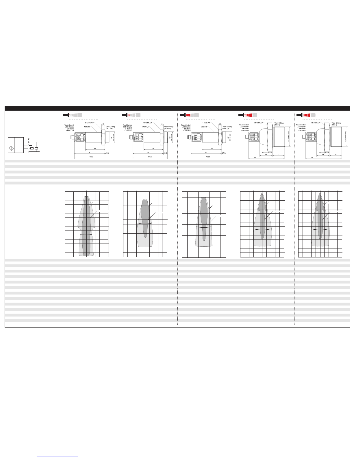
Detection zones
for different objects:
The dark grey areas are determined
with a thin round bar
and indicate the typical operating range
of a sensor. In order to obtain the light grey
areas, a plate (500 x 500 mm) is introduced
into the beam spread from the side.
In doing so, the optimum angle between
plate and sensor is always employed.
This therefore indicates the maximum
detection zone of the sensor.
It is not possible to evaluate ultrasonic
reflections outside this area.
Displayed is the detection zone at standard pressure.
At 1 bar overpressure the sensitivity of the sensor
will increase 5 times.
may be deactivated1) (0,17%/K without compensation)
may be deactivated1) (0,17%/K without compensation)
9 V to 30 V DC, short-circuit-proof
±10 %
9 V to 30 V DC, short-circuit-proof
±10 %
180 kHz
0.18 mm
120 kHz
0.18 mm
± 0,15 %
Temperature drift internal compensated, ≤2 %
Temperature drift internal compensated, ≤2 %
Temperature drift internal compensated, ≤2 %
may be deactivated1) (0,17%/K without compensation)
may be deactivated1) (0,17%/K without compensation)
9 V to 30 V DC, short-circuit-proof
±10 %
9 V to 30 V DC, short-circuit-proof
±10 %
may be deactivated1) (0,17%/K without compensation)
9 V to 30 V DC, short-circuit-proof
±10 %
No-load supply current
Ambient pressure
Housing
up to 6.0 bar
≤80 mA
up to 6.0 bar
Stainless steel 1.4571, plastic parts: PBT, TPU;
Ultrasonic transducer: PTFE film, FFKM O-ring
Stainless steel 1.4571, plastic parts: PBT, TPU;
Ultrasonic transducer: PTFE film, FFKM O-ring
Process connection
Class of protection to EN 60529
Norm conformity
Type of connection
G1
IP 67
G1
IP 67
EN 60947-5-2
5-pin initiator plug, PBT
EN 60947-5-2
5-pin initiator plug, PBT
up to 6.0 bar
Stainless steel 1.4571, plastic parts: PBT, TPU;
Ultrasonic transducer: PTFE film, FFKM O-ring
Stainless steel 1.4571, plastic parts: PBT, TPU;
Ultrasonic transducer: PTFE film, FFKM O-ring
up to 6.0 bar
Plastic parts: PVDF, PBT, TPU;
Ultrasonic transducer: PTFE film, FFKM O-ring
G1
IP 67
G2
IP 67
EN 60947-5-2
5-pin initiator plug, PBT
EN 60947-5-2
5-pin initiator plug, PBT
G2
IP 67
EN 60947-5-2
5-pin initiator plug, PBT
Controls
Indicators
Programmable
Operating temperature
2 push-buttons (TouchControl)
3-digit LED-display, 2 three-colour LEDs
2 push-buttons (TouchControl)
3-digit LED-display, 2 three-colour LEDs
Yes, with TouchControl and LinkControl
-25°C to +70°C
Yes, with TouchControl and LinkControl
-25°C to +70°C
Storage temperature
Weight
-40°C to +85°C
210 g
-40°C to +85°C
210 g
3 mm
11 Hz
5 mm
9 Hz
2 push-buttons (TouchControl)
3-digit LED-display, 2 three-colour LEDs
2 push-buttons (TouchControl)
3-digit LED-display, 2 three-colour LEDs
Yes, with TouchControl and LinkControl
-25°C to +70°C
Yes, with TouchControl and LinkControl
-25°C to +70°C
2 push-buttons (TouchControl)
3-digit LED-display, 2 three-colour LEDs
Yes, with TouchControl and LinkControl
-25°C to +70°C
-40°C to +85°C
210 g
-40°C to +85°C
1,200 g
20 mm
5 Hz
50 mm
3 Hz
-40°C to +85°C
350 g
50 mm
3 Hz
Time delay before availability
Order No.
65 ms
< 300 ms
84 ms
< 300 ms
hps+25/DD/TC/E/G1 hps+35/DD/TC/E/G1
Switched output
1) Can be programmed with TouchControl and LinkControl
2 x pnp, UB- 2 V, Imax = 2 x 200 mA
switchable NOC/NCC, short-circuit-proof
2 x pnp, UB- 2 V, Imax = 2 x 200 mA
switchable NOC/NCC, short-circuit-proof
160 ms
< 300 ms
240 ms
< 300 ms
hps+130/DD/TC/E/G1 hps+340/DD/TC/E/G2
240 ms
< 300 ms
hps+340/DD/TC/G2
2 x pnp, UB- 2 V, Imax = 2 x 200 mA
switchable NOC/NCC, short-circuit-proof
2 x pnp, UB- 2 V, Imax = 2 x 200 mA
switchable NOC/NCC, short-circuit-proof
2 x pnp, UB- 2 V, Imax = 2 x 200 mA
switchable NOC/NCC, short-circuit-proof
+UB
-UB
D1
D2
Sync/Com
1
2
4
5
3
2 pnp switched outputs
U
0 cm
5 cm
10 cm
15 cm
20 cm
25 cm
30 cm
35 cm
Plate
Round bar ø 10 mm
10 cm
5 cm
0 cm
5 cm
10 cm
0 cm
10 cm
20 cm
30 cm
40 cm
50 cm
60 cm
Plate
Round bar ø 10mm
20 cm
10 cm
0 cm
10 cm
20 cm
35 cm
0 m
0,4 m
0,8 m
1,2 m
1,6 m
2 m
1,3 m
Plate
Round bar ø 27 mm
0,8 m
0,4 m
0 m
0,4 m
0,8 m
0 m
0,8 m
1,6 m
2,4 m
3,2 m
4 m
4,8 m
5,6 m
3,4 m
Plate
Round bar ø 27 mm
1,6 m
0,8 m
0 m
0,8 m
1,6 m
0 m
0,8 m
1,6 m
2,4 m
3,2 m
4 m
4,8 m
5,6 m
3,4 m
Plate
Round bar ø 27 mm
1,6 m
0,8 m
0 m
0,8 m
1,6 m
The contents of this document are subject to technical changes. Specifications are presented in a descripted way only.
They
do
not
warrant
product
features.
microsonic GmbH • Hauert 16 • D-44227 Dortmund • Tel: +49 (0)2 31 / 97 51 51-0 • Fax: +49 (0)2 31 / 97 51 51-51 •E-Mail: [email protected] • www.microsonic.de