Ø
6
If the protection pressure switch remain placid when the
pressurein the water tank approaches 2mm below the brink of
the inner container, the protection pressure switch might be
broken or dislocated due to loose mounting screws.
Tighten the mounting screws and adjust the protection pressure
switch as follows: (1)Short circuit the normally open terminal
and the common terminal of the working pressure switch;
(2)Unscrew the fastening screws in the adjusting plate of water
level; (3)Turn counterclockwise the adjusting screw in the
adjusting plate of pressuretill the required water level;
(4)Remove the short circuit cord on the working pressure switch,
and wrench tight the fastening screws in the adjusting plate of
water level.
Try the pressureagain. If the pressureis higher than expected,
go over again the adjustment above till the requirement is met.
After adjustment, seal the screws with thread gum. Otherwise,
the screws may get loose, causing the pressureto change.
XIII. Water Pump Motor Assembly
XIV. Heating Element and Protective Thermostat
The heating element is located in the sump. When it is powered in the heated washing cycle, it warms up
the water, which will clean the dishes more effectively, and generates heat after washing to dry the
dishes.
The heating element has a nichrome filament inside. You can measure the resistance with a universal
meter to check its condition.
The protective thermostat is a temperature limitation switch and a safety device. In case the dishwasher
fails and the temperature inside the inner container rises above a specific limitation, the thermostat will
cut the heating element circuit to avoid any damage to the machine.
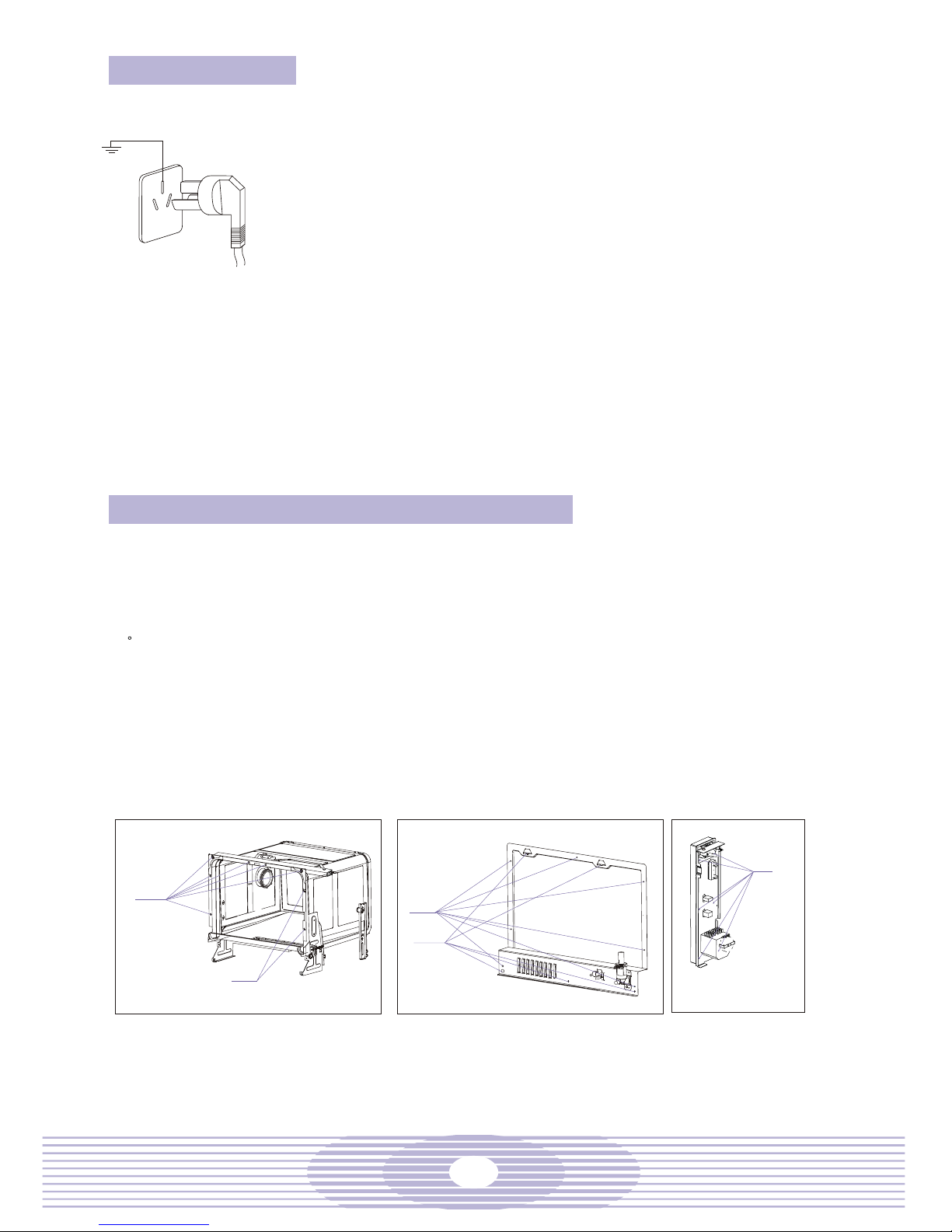
Steps for the check:
Remove the outer casing.
From the left side, you can see the heating element assembly installed to the end of the sump. Pull out
the connecting terminal of the heating element.
Check the heating element with an ohmmeter for damage and replace the damaged one.
Remove the connecting nut and the thermostat.
Remove the end cap of the heating element and take the heating element out of the sump.
Replace a new heating element and install the assembly as usual. Note: install the thermostat end with
heat conducting silicone grease, tighten the heating element nut, and secure the gasket and end cap.
The screws shall be wrenched tight. No leakage is allowed. The connecting terminal shall be upright, and
the heating element terminal shall be securely connected.
Connect the power cord and reinstall the machine.
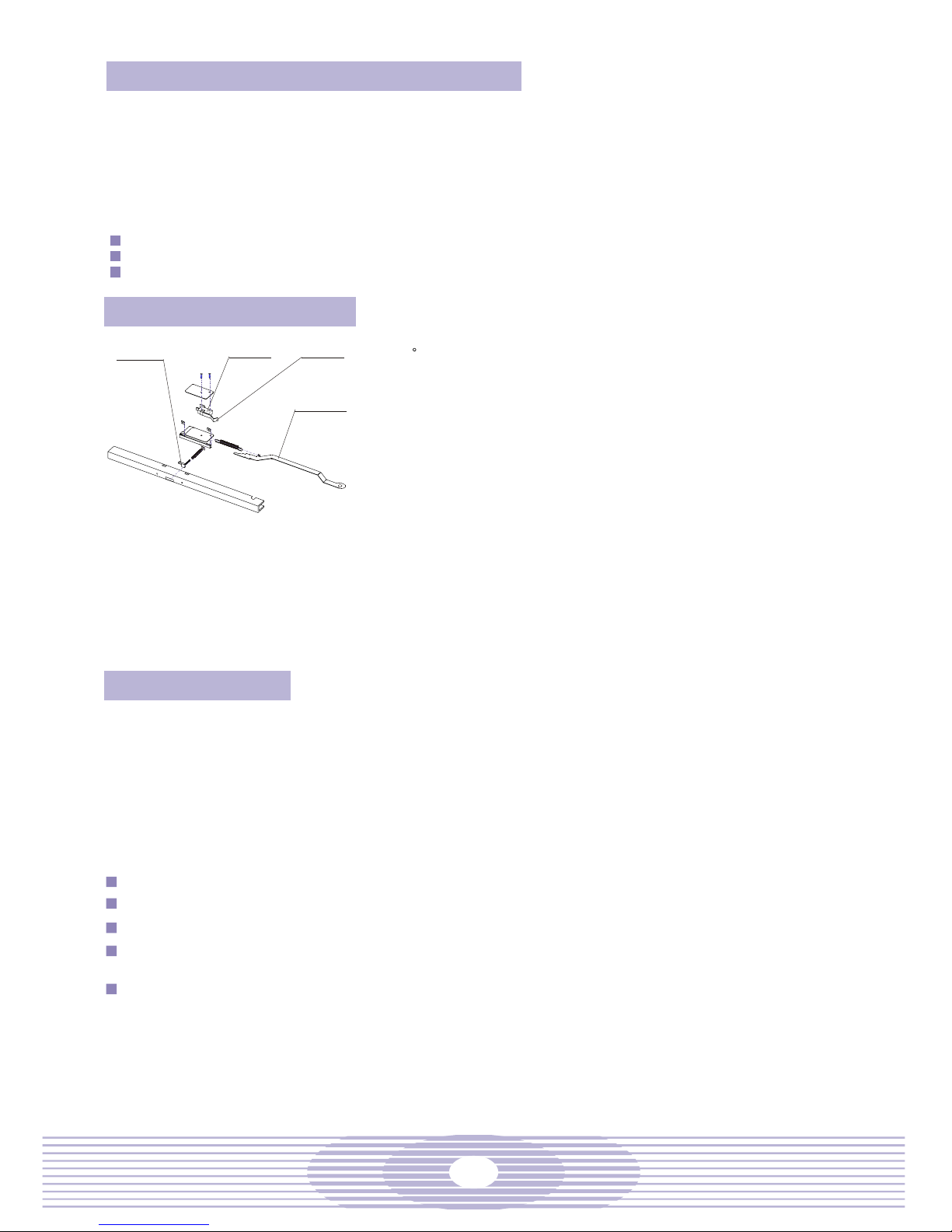
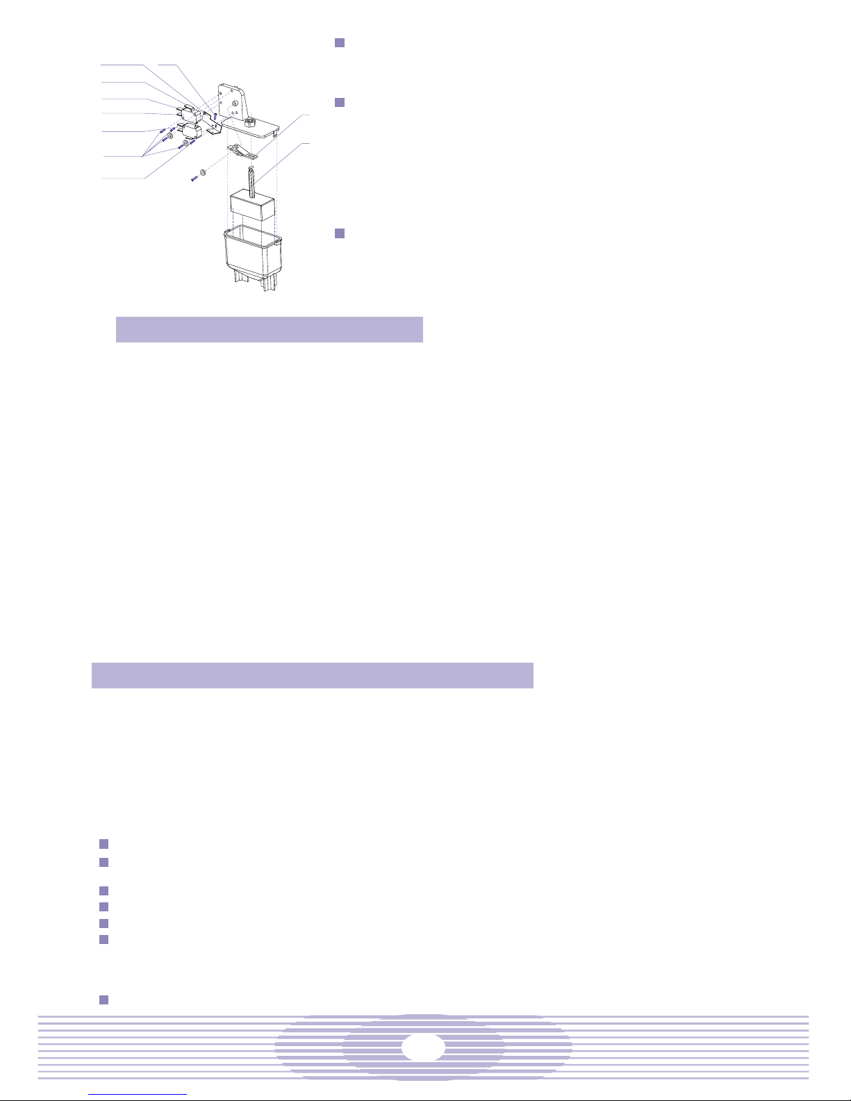
adjusting screw
common terminal
Lever
Float
normally open terminal
working pressure switch
protection pressure switch
Mounting screw
fastening screw
Water Pump Motor Assembly
The dish washing is a joint accomplishment of the circulation pump (77) and the drain pump (82). The
possible troubles of the water pump motor assembly include burnt motor coils, starting capacitor (74)
damage, damaged pump sealing spring, broken sealing, broken connecting tube, etc.
Steps for the check:
a. Remove the outer casing, and turn the dishwasher upside down.
b. Remove the connecting screws around the bottom pan and the screws to the circulation motor
support, the drain motor and the pressure switch bracing bar.
c. Check the capacitor and, if necessary, replace a new one.
d. Check the circulation pump for defects. In case of defective pump, replace it in the following manner:
(1) Remove the inlet hose wedge and the circulation pump; (2) Replace a new circulation pump; (3)
Put on a new inlet hose wedge and connect the tubes and wires; (4) Tighten the wedge.
e. Check the drain pump for defects. In case of defective pump, replace it in the following manner: (1)
Remove the inlet hose wedge and the drain pump; (2) Replace a new drain pump; (3) Put on a new
inlet hose wedge and connect the tubes and wires; (4) Tighten the wedge.
f. Check the connecting tubes and replaced the damaged ones.
Removal of Drainage Troubles
a. Check the drain hose for twist, air bubble or blockage and make necessary correction.
b. Check whether the motor is burnt. If so, replace the drain pump as specified above.