Miele G 349 Plus User manual

Installation instructions
for eye-level dishwashers
It is essential to read the operating and
installation instructions before
installing or using the machine,
to avoid the risk of accident or
damage to the machine.
G
M.-Nr. 05 585 961

These installation instructions apply to several different dishwasher models.
Model numbers in this booklet refer to the model designation specified
on the data plate on the machine (and not the description on the control
panel). The data plate is located at the top of the door when open.
The model numbers quoted refer only to the basic model number, e.g. the
G 349SC is described as the G 349 in this booklet.
It is essential to read the Warning and Safety Instructions in the Operating
Instruction booklet before installing the dishwasher.
2

Building in . . . . . . . . . . . . . . . . . . . . . . . . . . . . . . . . . . . . . . . . . . . . . . . . . . . . . . . 4
1. Measurements for building in . . . . . . . . . . . . . . . . . . . . . . . . . . . . . . . . . . . . . . . . 5
2. Fitting the control facia panel. . . . . . . . . . . . . . . . . . . . . . . . . . . . . . . . . . . . . . . . 6
3. Fitting the panel front . . . . . . . . . . . . . . . . . . . . . . . . . . . . . . . . . . . . . . . . . . . . . 8
4. Adjusting the dishwasher height . . . . . . . . . . . . . . . . . . . . . . . . . . . . . . . . . . . . . 8
5. Fitting the drain hose . . . . . . . . . . . . . . . . . . . . . . . . . . . . . . . . . . . . . . . . . . . . . . 9
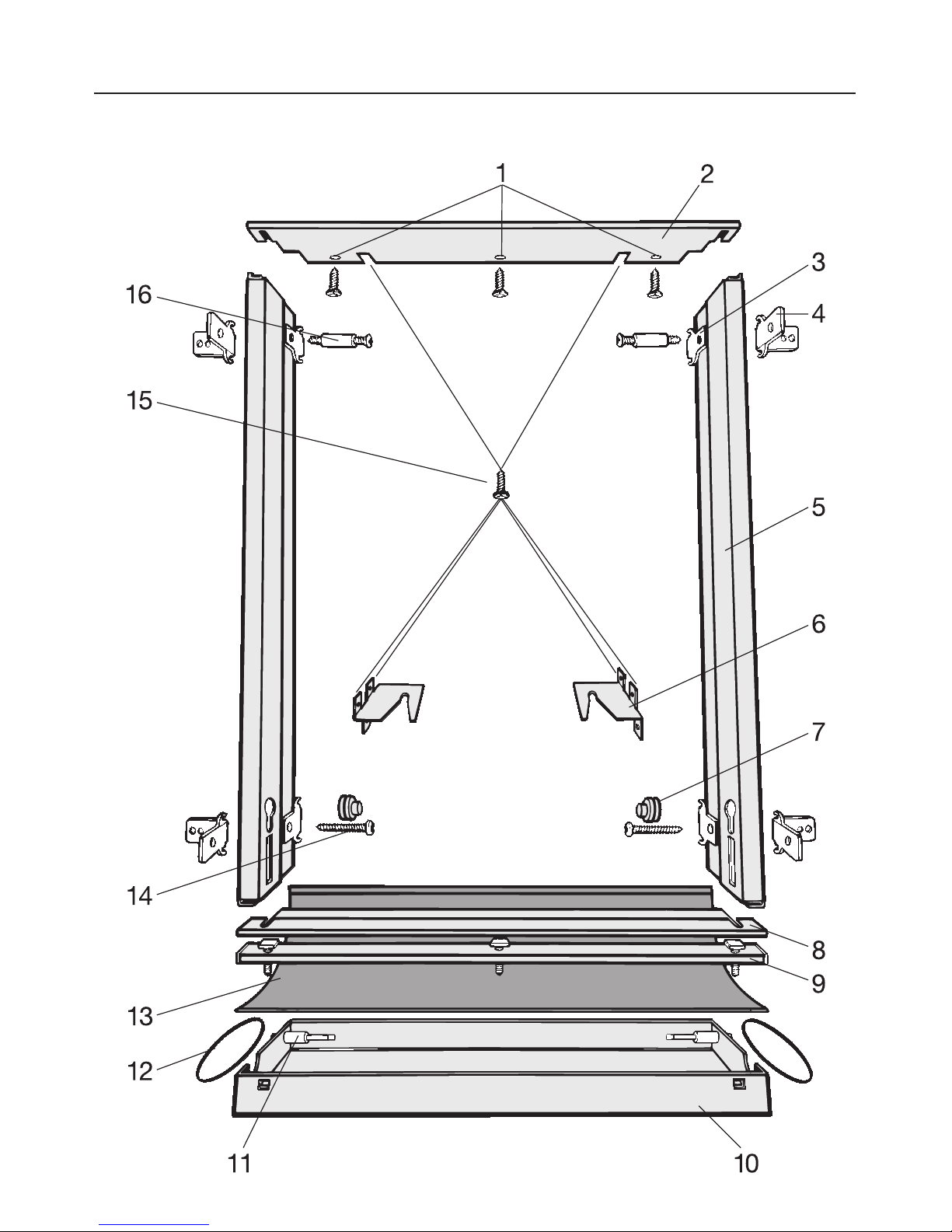
6. Building in kit . . . . . . . . . . . . . . . . . . . . . . . . . . . . . . . . . . . . . . . . . . . . . . . . . . . 10
7. Fitting the building-in frame and installing the dishwasher . . . . . . . . . . . . . . . . 12
Apply moisture protector . . . . . . . . . . . . . . . . . . . . . . . . . . . . . . . . . . . . . . . . . 12
Screw the foot holds and edge protector in place . . . . . . . . . . . . . . . . . . . . . 12
Fitting the side and top frame strips. . . . . . . . . . . . . . . . . . . . . . . . . . . . . . . . . 12
Fitting the dishwasher into the housing unit . . . . . . . . . . . . . . . . . . . . . . . . . . . 14
Aligning the dishwasher . . . . . . . . . . . . . . . . . . . . . . . . . . . . . . . . . . . . . . . . . . 14
To secure the dishwasher. . . . . . . . . . . . . . . . . . . . . . . . . . . . . . . . . . . . . . . . . 15
To fix the protective sheet. . . . . . . . . . . . . . . . . . . . . . . . . . . . . . . . . . . . . . . . . 16
To fit the bottom frame strip . . . . . . . . . . . . . . . . . . . . . . . . . . . . . . . . . . . . . . . 17
To fit the plinth facia . . . . . . . . . . . . . . . . . . . . . . . . . . . . . . . . . . . . . . . . . . . . . 17
8. Adjusting the door springs . . . . . . . . . . . . . . . . . . . . . . . . . . . . . . . . . . . . . . . . 18
Electrical connection. . . . . . . . . . . . . . . . . . . . . . . . . . . . . . . . . . . . . . . . . . . . . . 19
Plumbing. . . . . . . . . . . . . . . . . . . . . . . . . . . . . . . . . . . . . . . . . . . . . . . . . . . . . . . . 21
Connection to the water inlet . . . . . . . . . . . . . . . . . . . . . . . . . . . . . . . . . . . . . . . . . 21
Drainage . . . . . . . . . . . . . . . . . . . . . . . . . . . . . . . . . . . . . . . . . . . . . . . . . . . . . . . . 22
Venting the drainage system . . . . . . . . . . . . . . . . . . . . . . . . . . . . . . . . . . . . . . 22
Technical data . . . . . . . . . . . . . . . . . . . . . . . . . . . . . . . . . . . . . . . . . . . . . . . . . . . 23
Contents
3

This dishwasher is intended to be built
into a tall unit.
The following are needed:
–A facia panel (GW...),
–A dishwasher front, consisting of a
panel front and plinth facia (GFH 55),
–A building in frame (GER 60).
The facia panel and the front panel
must be fitted before the dishwasher is
built into the tall unit.
,To ensure stability this dish-
washer must only be built into a tall
unit. It must not be set up as a free-
standing machine.
The tall unit should be secured to
the wall for stability with the bracket
supplied.
,On dishwashers with a drying
fan, moist air is expelled through the
vent outlet in the front of the machine
at the end of a programme. It contin-
ues to be expelled for a certain
length of time or until the door is
opened.
To prevent damaging surrounding
fittings (e. g. worktops with wood
edging) the fan running time can be
increased to 45 minutes (see "Addi-
tional functions" in the Operating In-
struction manual for the machine).
Building in
4

1.Measurements for building in
The following conditions must be met:
– The recess floor must be capable of
bearing a load of at least 80 kg.
– The housing unit must be at least
550 mm deep.
– The installation duct (from base of
the recess to the floor) must be at
least 50 mm deep and 100 mm wide.
Normally connection to water is sited
near the dishwasher, for example in the
area under the sink. A Miele sink base
unit already has a suitable cut out for
installation. If the base unit has no
cut-out and if there is no opening
through the plinth area for connections,
one must be made.
Suggested dimensions: 60 x 110 mm.
The same applies to the tall unit in
which this dishwasher is to be installed.
,There must be no electrical
sockets behind the dishwasher.
Danger of overheating and fire risk if
the dishwasher were to be pushed
up against a plug.
Building in
5

2. itting the control facia
panel
The dishwasher must not be used until the control panel has been correctly fit-
ted.
Dishwashers with selector dial (G 349)
^Attach cap ato push button switch.
^Push the ventilation grille binto posi-
tion so that the slats on the grille are
facing downwards.
^Place the facia panel cin position
and use the six screws dto secure
in place through from the inside of
the door.
^Attach selector e.
Building in
6

Dishwashers with programme selector buttons (G 396)
^Attach cap ato push button switch.
^Push the ventilation grille binto posi-
tion so that the slats on the grille are
facing downwards.
^Place the facia panel cin position
and use the six screws dto secure
in place through from the inside of
the door.
^Insert the programme selector buttons
eand function buttons f.
Building in
7

3. itting the panel front
^Hang the panel front into the slits on
the machine door outer panel a.
^Tighten fixing screws bon both
sides of the door outer panel.
^Plug openings busing the plastic
stoppers supplied.
4.Adjusting the dishwasher
height
^Adjust the machine feet evenly until
the height of the dishwasher just
reaches the height of the recess.
^Press the slides with the ratchet at
the rear under the screw feet.
(You will find the slides in the upper
basket of the dishwasher).
Building in
8

5. itting the drain hose
The drain hose is in the wash cabinet.
The connection stub is located low
down on the rear side of the dish-
washer.
^Connect the drain hose using the
hose clip supplied.
The connection stub can be turned.
The hose can be laid to the right or left
without needing to loosen the hose clip.
Building in
9

6. Building in kit
Building in
10

Position Description Quantity
1 Counter sunk screws 4 x 15 3
2 Top frame strip 1
3 Spacer for unit wall thickness 16 mm 4
4 Spacer for unit wall thickness 19 mm 4
5 Side frame strips 2
6 Foot holds 2
7 Stoppers 2
8 Bottom frame strip 1
9 Spacer bar 1
10 Plinth facia 1
11 Plinth facia retainer 2
12 Rubber rings 2
13 Protective sheet 1
14 Wood screws 4 x 20 2
15 Wood screws 4 x 15 6
16 Wood screws 4 x 30 with sleeve 2
not illustrated Edge protector 1
Flat head screws 3.5 x 9.5 2
Building in
11

7. itting the building-in frame
and installing the dish-
washer
Apply moisture protector
^Seal the cracks between the side
walls and the recess floor and any
unprotected cut surfaces with the sili-
cone sealant provided.
Screw the foot holds and edge
protector in place
^Secure the foot holds (6) with two
wood screws each 4 x 15 (15) to the
side walls of the housing unit.
The distance from the front edge of
the unit to the front edge of the foot
holds must measure 450 mm .
The bottom bracket must rest on the
recess floor.
^Secure the edge protector to the front
edge of the unit floor using two
3.5 x 9.5 mm flat head screws. This
protects the front edge of the unit
base when fitting or removing the
dishwasher.
itting the side and top frame strips
With a recess width of 562 mm (unit
wall thickness 19 mm) spacer pieces
(3) fitted to the side frame strips should
be replaced by the thinner spacers
should be replaced by the thinner
spacers supplied (4).
^Unfold spacer (3) and remove.
^Fit spacer (4) and fold back in.
Building in
12

^Place side frame strips (5) into the
housing unit A.
^Push the top frame strip (2) into
position B.
^Screw the top frame strip to the re-
cess ceiling using the 4 x 15 (1)
countersunk screws.
^Screw the side frame strips to the
bottom of the side walls using the
4 x 20 (14) wood screws.
Building in
13

itting the dishwasher into the
housing unit
^Lay the hoses and cable into the unit
and down through the installation
duct.
^Push the dishwasher into the unit re-
cess.
The back feet should rest in the
openings of the footholds.
,Ensure the hoses and cable do
not get kinked or squashed.
Aligning the dishwasher
^Shut the dishwasher door.
^Screw the machine feet out until the
dishwasher is touching the recess
ceiling.
^Use a Torx T20 screwdriver to adjust
the rear screw feet to the required
height.
higher = turn clockwise
lower = turn anti-clockwise
Several turns are needed to adjust
1 mm in height.
Building in
14

^Adjust the front screw feet manually
or with a flat blade screwdriver.
^Align the dishwasher:
- the gap between the panel front
and the side frame strips must
match,
and
- the facia control panel and the
panel front must sit flush with the
building in frame.
To secure the dishwasher
^Open the dishwasher door.
^Screw a 4 x 15 (15) wood screw from
below into the holes in the right and
left hand side of the upper strip.
^Remove the cover caps from the side
openings, left and right.
^Secure the dishwasher on both sides
with the 4 x 30 wood screws with
sleeves (16).
Building in
15

^Put the cover caps back in the open-
ings. Use the extra ones supplied if
necessary.
To fix the protective sheet
^Remove the backing from the
adhesive strip.
^Stick the protective sheet (13) on the
plinth along the edge below the
screws.
Building in
16

To fit the bottom frame strip
Recess height 876 mm:
^Push the bottom frame strip (8) over
the lower ends of the side frame
strips (5).
Recess height 882 mm:
^First push the spacer bar (9) from be-
low onto the bottom frame strip.
^To do this loosen the nuts in the
spacer bar, push the spacer bar onto
the bottom frame strip and tighten the
nuts again.
^File off any protruding screw ends.
Recess height greater than 882 mm:
^In this case a package must be put
together of spacer bars (special ac-
cessory) to suit the niche height and
pushed under the bottom frame strip.
To fit the plinth facia
^Fit stoppers (7) into the "Key-holes" in
the side frame strips A.
^Pull the handle for the plinth facia
(11) forward and push outward until it
engages B.
^Fit rubber bands (12) over the spacer
pieces and into the plinth facia.
^Flap up the plinth facia.
Building in
17

8.Adjusting the door springs
The door springs are correctly adjusted
when the door remains stationary when
left open at 45 °.
If the door drops down, then the door
springs need to be tightened.
If it closes then the springs need to be
loosened.
The adjusting screw is located in the
upper front strip at the left hand side of
the dishwasher.
^Half open the dishwasher door.
The door springs are easier to adjust
when the door is only half open than
when it is fully open.
^Adjust the door spring with a Torx
T20 or a 1 x 5.5 mm screwdriver until
it is correctly balanced:
- turn clockwise = tighten
- turn anti-clockwise = loosen.
Building in
18

,Please follow the installation in-
structions carefully.
All electrical work should be carried
out only by a suitably qualified and
competent person, in strict accor-
dance with national and local safety
regulations.
Ensure power is not supplied to the
appliance while installation work is
being carried out.
This dishwasher is supplied with a
mains cable and moulded plug ready
for connection to an a.c. single phase
supply, (230 -240 V 50 Hz for the UK
and Australia) via a fused plug and suit-
able switched socket which is easily
accessible after installation.
^The voltage, rated load and fuse rat-
ing are given on the data plate lo-
cated above the door. Please ensure
that these match the household
mains supply.
For extra safety it is advisable to install
a residual current device (RCD), with a
trip current of 30 mA (in accordance
with DIN VDE 0664, VDE 0100 Section
739).
^Do not connect via an extension lead.
Danger of overheating.
,If the connection cable is dam-
aged it must be replaced with a
complete connection box and cable
by a Miele approved service techni-
cian only.
Important
If this machine is fitted with a
non-rewireable plug (BS 1363) and the
socket outlets are not suitable for the
plug supplied or if the existing plug
needs to be replaced by a new one, the
old plug will need to be cut off and an
appropriate plug fitted. The fuse carrier
and the fuse should be removed from
the old plug and disposed of.
The plug cut from the cable should then
be disposed of and on no account be
inserted into any socket elsewhere in
the house (electric shock hazard).
The fuse cover must be refitted when
changing the fuse, and if the fuse cover
is lost, the plug must not be used until a
suitable replacement is obtained. The
colour of the correct replacement cover
is that of the coloured insert in the base
of the plug, or the colour that is em-
bossed in words on the base of the
plug (as applicable to the design of
plug fitted).
The correct fuse rating of the replace-
ment fuses that are ASTA approved to
BS 1362 should be fitted. Replacement
fuse covers may be purchased from
your local electrical supplier or Miele
Service Agent.
Electrical connection
19

The wires in the mains lead are col-
oured in accordance with the following
code:
Green/yellow = earth
Blue = neutral
Brown = live
If the colours of the wires in the mains
lead of this appliance do not corre-
spond with the coloured markings iden-
tifying the terminals of your plug, pro-
ceed as follows:
^The wire which is coloured green and
yellow must be connected to the ter-
minal in the plug which is marked
with the letter E or by the earth sym-
bol zor coloured green, or green
and yellow.
^The wire which is coloured blue must
be connected to the terminal in the
plug which is marked with the letter N
or coloured black.
^The wire which is coloured brown
must be connected to the terminal in
the plug which is marked with the let-
ter L or coloured red (UK), or marked
with the letter A (AUSTRALIA).
WARNING:
THIS APPLIANCE
MUST BE EARTHED
Electrical connection
20
Other manuals for G 349 Plus
1
This manual suits for next models
2
Table of contents
Other Miele Dishwasher manuals

Miele
Miele PG 8164 Instruction manual

Miele
Miele G 5266 SCVi SF User manual

Miele
Miele G 5225 SC User manual

Miele
Miele G 832 SC User manual

Miele
Miele Classic G 4270 SCVi Parts list manual

Miele
Miele G2872SC User manual

Miele
Miele G 2142 User manual

Miele
Miele G 666 User manual

Miele
Miele G 7561 User manual

Miele
Miele tx2349 User manual

Miele
Miele G 8050 User manual

Miele
Miele PG 8080 U User manual

Miele
Miele G 651 Plus User manual

Miele
Miele G 4920 User manual

Miele
Miele G6360 User manual

Miele
Miele G 2383 SCVi XXL User manual

Miele
Miele G 691 User manual

Miele
Miele G1142 User manual

Miele
Miele PG 8059 User manual

Miele
Miele Classic G 4205 Manual