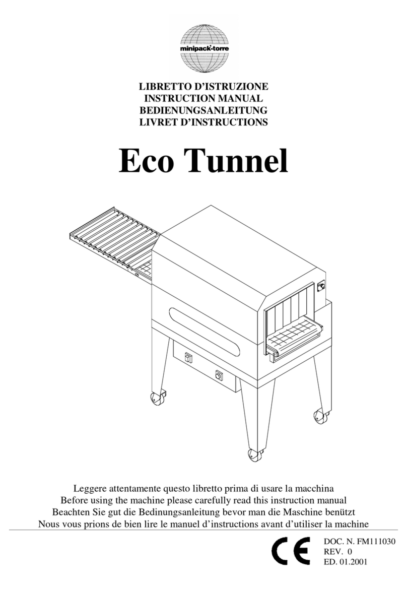
Miller Weldmaster PS150 User manual


1.0 Machine Overview …………………………………………………………………… 1
1.1 Intended Use ………………………………………………………………………………… 1
1.2 Explanation of Warnings …………………………………………………………………… 2
1.3 Electrical and Air Requirements …………………………………………………………… 4
1.3.1 Preparation - World Power ………………………………………………………… 4
1.3.2 Electrical Supply ……………………………………………………………………… 4
1.3.3 Shop Air Supply ……………………………………………………………………… 5
1.4 Principles of Heat Sealing ………………………………………………………………… 5
1.5 Controls: Purposes and Functions ………………………………………………………… 6
1.5.1 Operator Control Screen …………………………………………………………… 6
1.5.2 Main Menu Screen, Operator Level ………………………………………………… 7
1.5.3 Operator Configuration, Operator Level …………………………………………… 8
1.5.4 Main Menu Screen, SU Level ……………………………………………………… 9
1.5.5 Recipe Configuration Screen ………………………………………………………10
1.5.6 Recipe Active Screen ………………………………………………………………12
1.5.7 Heat Control Weld Nozzle Screen …………………………………………………13
1.5.8 Heat Control Pre Heat Nozzle Screen ……………………………………………14
1.5.9 Machine View Operator Panel Screen ……………………………………………15
1.5.10 Machine View Top Slide Screen …………………………………………………16
1.5.11 Remote Interface Screen …………………………………………………………16
1.5.12 Active Alarm Screen ………………………………………………………………17
1.5.13 Alarm History Screen ………………………………………………………………17
1.5.14 Information Screen …………………………………………………………………17
1.5.15 Login Screen ………………………………………………………………………18
1.5.16 Machine Configuration Screen ……………………………………………………18
1.5.17 SU maintenance ……………………………………………………………………20
1.5.18 Manual Menu Screen ………………………………………………………………22
2.0 Machine Specifications
2.1 Features ………………………………………………………………………………………25
2.2 Technical Specifications ……………………………………………………………………25
2.3 Features and Functions ……………………………………………………………………25
2.3.1 Mechanical Section …………………………………………………………………25
Table of Content
2.3.2 Operator Controls Section ……………………………………………………………26
2.3.3 Pneumatic System ……………………………………………………………………26
3.0 Component Replacement and Maintenance …………………………27
3.1 Replacement of Heating Element …………………………………………………………27
3.2 Maintenance …………………………………………………………………………………27
3.2.1 Electrical Circuits ……………………………………………………………………27
3.2.2 Drive System …………………………………………………………………………28
3.2.3 Maintaining Belts and Pulleys ………………………………………………………28
3.3 Machine Adjustments ………………………………………………………………………29
3.3.1 Hot Air Heat System Adjustment …………………………………………………………29
3.3.2 Adjusting the Height of the Machine ……………………………………………………30
3.3.3 Transportation and Storage …………………………………………………………30
3.3.4 Technical Requirements ……………………………………………………………31
1.1: Intended Use
The PS150 is a rotary hot air welding machine intended to heat-seal weldable thermal
plastics such as:
Polypropylene (PP) Coated Fabric
Polyethylene (PE) Coated Fabrics
The manufacturer does not approve of:
Any other uses for these machines.
The removal of any safety guards while in operation.
Unauthorized modification of the machines.
Using replacement parts that are not manufacturer-approved.
Only a properly-trained technician may operate and/or perform any routine
maintenance or repairs to the machines.
NOTE: The manufacturer will not be held liable for any damage or injuries occurring
from any inappropriate use of this machine.
Table of Content (continued)
1.0: Machine Overview
CHAPTER 1: MACHINE OVERVIEW

CHAPTER 1: MACHINE OVERVIEW 2
1.2: Explanation of Warnings
There are several different warning symbols placed on the Miller Weldmaster PS150. These symbols
are to alert the operator of potentially hazardous areas on the machine. Familiarize yourself with the
their placement.
Caution: Hot. (fig.01)
The “Caution: Hot” symbol is placed on a guard near hot
surfaces.
Danger: Pinch Points. (fig.02)
The “Danger: Pinch Points” symbol is placed near any potential
pinch points. Do not place any body parts near these sections
of the machine while the machine is running.
Caution: Unplug Machine. (fig.03)
The “Caution: Unplug Machine” sticker is placed near the open-
ing of the cabinet and all access panels. To prevent electrocu-
tion, the machine should always have the power disconnected
before the cabinet door is open.
Warning: Keep Hands Clear. (fig.04)
The “Warning: Keep Hands Clear” sticker is placed on the
Heater Assembly. To prevent any pinching or burns, be aware
of the location of your hands at all times.
(fig.01) Caution: Hot
(fig.02) Danger: Pinch Points
(fig.03) Caution: Unplug Machine
(fig.04) Warning: Keep Hands Clear

CHAPTER 1: MACHINE OVERVIEW
1.2: Explanation of Warnings (continued)
Warning: High Temperature Air (fig.05)
The “Warning: High Temperature Air” sticker is placed on the
Heater Assembly.
Caution: Electricity (fig.06)
The “Caution: Electricity” sticker is placed near areas that contain
electrical components.
Caution: Sharp (fig.07)
The “Caution: Sharp” sticker is placed near areas that contain
sharp components.
(fig.05) Warning: High Temperature Air
(fig.06) Caution: Electricity
3
Lockout Tagout (fig.08):
Each AC variable frequency drive power is supplied by a fuse block
which can be locked out and tagged out. A screw driver is used in
the slot on the face of the handle to start the handle to open. Once
started then the user can pull open by hand and lockout tagout the
device.
(fig.08) Caution: Electricity
(fig.07) Caution: Sharp

CHAPTER 1: MACHINE OVERVIEW
Warning! Only a qualified electrician may connect the electrical power.
4
1.3: Electrical and Air Requirements
1.3.1: Preparation - Power and Air
1. Make sure the Power Supply is at 230v, 30amp, 50/60hz or 480v,30amp, when the appropriate
step down transformer has been supplied, 50/60hz. and the Pressure Supply comes up to 100
psi (6.9 bar) when the machine is working.
2. Make sure the voltage and current is dedicated to the machine and to the above specification.
3. An appropriate ground connection must be made to the ground terminal provided on the ma-
chine.
4. Before operation of the machine be sure the surrounding area of the machine is free of
flammable debris. Only authorized persons should be in the area of the machine while in use.
5. In the event of an emergency, press the Emergency Stop Button
1.3.2: Electrical Supply
Due to the number of different style outlets available, the cord will not include a plug. It is recom-
mended that your electrician install a plug that is comparable to your style power outlet. You may
choose to have your power cord hard-wired into your Power Supply. It is recommended that your
electrician use a Junction Box with an ON/OFF switch. The Miller Weldmaster PS150 requires one
of the following electrical requirements:
30 Amp - Three phase - 230 Volts
30 Amp - Three phase - 480 Volts (When the appropriate step down transformer has
been supplied)
The Attention (fig.09):
The tag is located near the lower limit of the height adjustment sys-
tem. Once the machine has been adjusted to the desired operating
height then raise the clamping collar to bottom of bracket and tighten
in place. By doing so creates a lower height adjustment limit so that
the machine will lower a minimal amount from operation height.
(fig.09) Caution: Electricity
1.2: Explanation of Warnings (continued)

1.4: Principles of Heat Sealing
Heat: Hot Air Heating System: The Heat required for the welding operation is created elec-
trically by one (or two depending on the application) heating element located inside the Heat
Element Housing. The shop air supply provides air over the heat element and carries the heat
through the Hot Air Nozzel, applying the heat to the material to be welded. The hot air tempera-
ture ranges from 25 to 800 Degrees Celsius (77 to 1472 Degrees Fahrenheit).
Speed: The Speed of the Weld Rollers determines the amount of time the heat is applied to the
material being welded. The slower the speed setting, the more the material will be heated. The
faster the speed setting, the less the material will be heated. To achieve the best weld, a minimal
amount of heat should be applied to the material while still achieving a full weld. Too much heat
will cause distortion of the material; while not enough heat will prevent the material from welding.
Pressure: The Pressure of the Weld Rollers compresses the heated material together to com-
plete the welding process.
Summary
The correct combination of Heat, Speed, and roller Pressure will allow you to achieve a properly-
welded seam.
CHAPTER 1: MACHINE OVERVIEW
5
1.3.3 Shop Air Supply
The Miller Weldmaster PS150 includes an In-Shop Air Supply
Valve that allows quick connects and disconnects to your shop
air supply. Due to the number of different style airline connectors,
a male quick-connect is not included. You will want to select a
male quick- connect with a 3/8 inch NPT (National Pipe Thread) to
match your female quick-connect. The Miller Weldmaster PS150
requires the following shop air requirements:
Minimum of 20 cfm at 100 psi
Not to exceed 565 liters/min at 6.9 Bar
An in-line water and dirt separator
(fig.10)

1.5: Controls: Purposes and Functions
1.5.1: Operator Control Screen
Top center text box: The text field will list current alarms.
The up/down buttons next to the text box will allow the user to
scroll up/down the list of current alarms.
MSG0 text box: The text box field will indicate the current
state on the machine. System Idle, System Running, Pause,
Forward Job, Conv Door Open, Alarm Active, Reset EPO, Op-
erator Control Side E-Stop, and Non Operator Control Side
E-Stop
Red indicator light: The red indicator light will display the
same color as the stack light in the solid color mode.
0 Bag/Min: The “0” indicates the current average bags per
minute passing through the machine.
0 Feet/Min: “0” indicates the current average bags per min-
ute passing through the machine.
Weld Nozzle OFF: Pressing the button will toggle the heat
system on/off. Press once to toggle to the opposite condition.
Actual (F): The number displayed is at what temperature the
thermo-couple is currently reading at the base of the element
housing.
Setpoint (F): The number displayed is at what temperature the
temperature controller is being told to hold temperature at. By
touching the text box on the screen a key pad will appear allow-
ing the user to change the setpoint.
Pre-Heat Nozzle OFF: Tressing the button will toggle the
heat system on/off. Press once to toggle to the opposite condi-
tion.
Actual (F): The number displayed is what temperature the
thermo-couple is currently reading at the base of the element
housing.
Setpoint (F): The number displayed is at what temperature the
temperature controller is being told to hold temperature at. By
touching the text box on the screen a key pad will appear allow-
ing the user to change the setpoint.
(fig.11) Operator Control Screen
Principles of Operation
The PS150 is a heat sealing machine which welds thermal plastic fabrics or films by Hot Air,
through applying pressure, consistent speed, and accurate temperature for perfectly sealing thermal
plastic materials.
CHAPTER 1: MACHINE OVERVIEW 6

1.5.1: Operator Control Screen (continued)
Weld Roller: Pressing the button will open/close the weld rollers.
Press once to toggle to the opposite condition.
Transport Belt: Pressing the button will open/close the transport
belts. Press once to toggle to the opposite condition.
Jog FWD: Pressing the button will jog the drive system in the for-
ward direction at a slow rate of speed. This function is intended to
test motion of the motors and drive system only. It is not intended
to operation in a synchronized function. Jog FWD will only appear
when the machine is in a paused state.
Menu: Pressing the menu button will take the user to the Main
Menu screen.
1.5.2: Main Menu Screen, Operator Level:
Operator Config: Pressing the Operator Configuration button will
take the user to the Operator Configuration, Operator Level.
Alarms History: Pressing the Alarm History button will take the
user to the Alarm History Screen.
Machine View: Pressing the Machine View button will take the
user to the Machine View Operator Side Screen.
Login: Pressing the Login button will take the user to the Login
Screen.
Logout: Pressing the Logout button will Logout and return user to
the base viewable screens.
Operation: Pressing the Operation button will take the user to the
Operator Control Screen.
CHAPTER 1: MACHINE OVERVIEW
7
(fig.12) Main Menu Screen, Operator
control

1.5.3: Operator Configuration, Operator
Level:
Recipe Number: The number displayed in the text box is
the number of the recipe currently displayed. By touching
the text box on the screen a key pad will appear allowing
the user to change to the desire recipe number. The up/
down arrow located to the right/left of the text box will also
adjust to the next recipe. By touching the arrow once the
recipe will change to the next recipe.
Recipe Name: The text displayed is what the current
recipe has been named. By touching the text box on the
screen a key pad will appear allowing the user to change
the text.
Activate: Pressing the activate button will load the saved
setting of the displayed recipe to the appropriate set
points. When adjusting a speed setting for example, the
speed setting must be changed then the activate button
must be pressed in order to send the change to that par-
ticular set point.
Transport Belt (FT/MIN): The number displayed in the
text box is the speed at which the Transport Belt is set.
The Transport speed is the master speed of the machine.
The number is in feet per minute. By touching the text box
on the screen a key pad will appear allowing the user to
change the Transport belt speed. By touching the arrow
once the speed will be increased/decreased by 0.01 ft/
min. Once the desired set point has been entered into the
text box the user must press the activate button in order to
send the change to that particular set point.
Front Weld Roller (FT/MIN): The number displayed in
the text box is at what speed the Front Weld Roller is set.
The speed of the Front Weld Roller is a slave to the Trans-
port Speed, but can be offset. The number is in feet per
minute. By touching the text box on the screen a key pad
will appear allowing the user to change the Front Weld
Roller speed. By touching the arrow once the speed will
be increased/decreased by 0.01 ft/min. Once the desired
set point has been entered into the text box the user must
press the activate button in order to send the change to
that particular set point.
CHAPTER 1: MACHINE OVERVIEW 8
(fig.13) Recipe Configuration Screen

1.5.3: Operator Configuration, Operator Level: (continued):
Rear Weld Roller: The speed of the Rear Weld Roller is a slave to the Transport Speed. The num-
ber is in feet per minute. By touching the text box on the screen a key pad will appear allowing the
user to change the Rear Weld Roller speed. The up/down arrow located to the right/left of the text
box will also adjust the speed of the Rear Weld Roller. But touching the arrow once the speed will
be increased/decreased by 0.01 ft/min. Once the desired set point has been entered into the text
box the user must press the activate button in order to send the change to that particular set point.
Weld Nozzle Temp (F): The number displayed is at what temperature the temperature control-
ler is being told to hold temperature. By touching the text box on the screen a key pad will appear
allowing the user to change the Setpoint. The up/down arrow located to the right/left of the text
box will also adjust the setpoint. By touching the arrow once the temperature will be increased/de-
creased by 1’f. Once the desired set point has been entered into the text box the user must press
the activate button in order to send the change to that particular set point.
Pre Heat Temp (F): The number displayed is at what temperature the temperature controller is be-
ing told to hold temperature. By touching the text box on the screen a key pad will appear allowing
the user to change the Setpoint. The up/down arrow located to the right/left of the text box will also
adjust the setpoint. By touching the arrow once the temperature will be increased/decreased by 1’f.
Once the desired set point has been entered into the text box the user must press the activate but-
ton in order to send the change to that particular set point.
No Bag Time (SEC): The input bag sensor controls when the nozzle swing system is told to be in
the welding position and when to be in the home position when the machine is in run mode. When
a bag enters the machine and the sensor sees the bag, the nozzle swing system is told to swing
into the weld position. The number displayed in the text box is the amount of time which must pass
without a bag passing the input bag sensor. If this amount of time is reached, then the nozzle swing
system is told to go to it’s home position until another bag is sensed. By touching the text box on
the screen a key pad will appear allowing the user to change the setpoint.
Save: Pressing the save button will save/resave all of the current setpoint entered into each par-
ticular text box to the currently displayed recipe.
Jog FWD: Pressing the button will jog the drive system in the forward direction at a slow rate of
speed. This function is intended to test motion of the motors and drive system only. It is not intend-
ed to operate in a synchronized function. Jog FWD will only appear in the paused condition
Previous: Pressing the previous button will display the previous screen.
CHAPTER 1: MACHINE OVERVIEW
9
1.5.4: Main Menu Screen, SU level:
Operator Config: Pressing the Operator Configuration
button will take the user to the Operator Control Screen.
Alarm History: Pressing the Alarm History button will
take the user to the Alarm History Screen.
Machine View: Pressing the Machine View button will
take the user to the Machine View Operator Side Screen.
(fig.14) Main Menu Screen, SU level

1.5.4: Main Menu Screen, SU level (continued):
Recipe Config: Pressing the Recipe Config button will take the user to the Recipe Con-
figuration Screen.
Recipe Active: Pressing the Recipe Active button will take the user to the Recipe Active
Screen.
Heat/Manual: Pressing the Heat/Manual button will take the user to the Heat Control
Weld Nozzle Screen.
Machine Config: Pressing the Machine Config button will take the user to the Operator
Control Screen.
Remote Info: Pressing the Remote Info button will take the user to the Remote Info
Screen.
HMI Setup: Pressing the HMI Setup button will take the user to the HMI Setup Screen.
Alarms Active: Pressing the Alarm Active button will take the user to the Alarm Active
Screen.
Info: Pressing the Info button will take the user to the Info Screen.
Login: Pressing the Login button will take the user to the Login Screen.
Logout: Pressing the Logout button will take the user to the base viewable screens.
SU Maint: Pressing the SU Maint button will take the user to the SU Maintenance
Screen.
CHAPTER 1: MACHINE OVERVIEW 10
Recipe Number: the number displayed in the
text box is the number of the recipe currently
displayed. By touching the text box on the screen
a key pad will appear allowing the user to change
to the desire recipe number. The up/down arrow
located to the right/left of the text box will also ad-
just to the next recipe. By touching the arrow once
the recipe will increased/decreased by 1.
Recipe Name: The text displayed is what the
current recipe has been named. By touching the
text box on the screen a key pad will appear allow-
ing the user to change the text.
(fig.15) Recipe Configuration Screen
1.5.5: Recipe Configuration Screen:

CHAPTER 1: MACHINE OVERVIEW
11
1.5.5: Recipe Configuration Screen (continued):
Activate: Pressing the activate button will load the saved setting of the displayed recipe to the
appropriate set points. When adjusting a speed setting for example, the speed setting must be
changed when the activate button must be pressed in order to send the change to that particular
set point.
Transport Belt (FT/MIN): The number displayed in the text box is at what speed the transport
belt is set. The Transport speed is the master speed of the machine. The number is in feet per
minute. By touching the text box on the screen a key pad will appear allowing the user to change
the Transport belt speed. The up/down arrow located to the right/left of the text box will also
adjust the speed of the Transport. By touching the arrow once the speed will be increased/de-
creased by 0.01 ft/min. Once the desired set point has been entered into the text box the user
must press the activate button in order to send the change to that particular set point.
Front Weld Roller (FT/MIN): The number displayed in the text box is at what speed the Front
Weld Roller is set. The speed of the Front Weld Roller is a slave to the Transport Speed, but can
be offset. The number is in feet per minute. By touching the text box on the screen a key pad will
appear allowing the user to change the Front Weld Roller Speed. The up/down arrow located to
the right/left of the text box will also adjust the speed of the Rear Weld Roller. By touching the
arrow once the speed will be increased/decreased by 0.01 ft/min. Once the desired set point
has been entered into the text box the user must press the activate button in order to send the
change to that particular set point.
Rear Weld Roller (FT/MIN): The number displayed in the text box is at what speed the Rear
Weld Roller is set. The speed of the Rear Weld Roller is a slave to the Transport Speed, but can
be offset. The number is in feet per minute. By touching the text box on the screen a key pad will
appear allowing the user to change the Rear Weld Roller Speed. The up/down arrow located to
the right/left of the text box will also adjust the speed of the Rear Weld Roller. By touching the
arrow once the speed will be increased/decreased by 0.01 ft/min. Once the desired set point
has been entered into the text box the user must press the activate button in order to send the
change to that particular set point.
Weld Nozzle Temp (F): The number displayed is at what temperature the temperature control-
ler is being told to hold temperature. By touching the text box on the screen a key pad will appear
allowing the user to change the Setpoint. The up/down arrow located to the right/left of the text
box will also adjust the set point. By touching the arrow once the speed temperature will be in-
creased/decreased by 1’f. Once the desired set point has been entered into the text box the user
must press the activate button in order to send the change to that particular set point.

CHAPTER 1: MACHINE OVERVIEW 12
1.5.5: Recipe Configuration Screen (continued):
Pre Heat Temp (F): The number displayed is at what temperature the temperature
controller is being told to hold temperature. By touching the text box on the screen a
key pad will appear allowing the user to change the Setpoint. The up/down arrow lo-
cated to the right/left of the text box will also adjust the set point. By touching the arrow
once the temperature will be increased/decreased by 1’f. Once the desired set point
has been entered into the text box the user must press the activate button in order to
send the change to that particular set point.
No Bag Time: The input bag sensor controls when the nozzle swing system is told to
be in the welding position and when to be in the home position when the machine is
in run mode. When a bag enters the machine and the sensor sees the bag the nozzle
swing system is told to swing into the weld position. The number diplayed in the text
box is the amount of time which must pass without a bag passing the input bag sensor.
If this amount of time is reached, then the nozzle swing system is told to go to it’s home
position until another bag is sensed. By touching the text box on the screen a key pad
will appear allowing the user to change the setpoint.
Save: Pressing the save button will save/resave all of the current setpoint entered into
each particular text box to the currently displayed recipe.
Jog FWD: Pressing the button will jog the drive system in the forward direction at a
slow rate of speed. This function is intended to test motion of the motors and drive
system only. It is not intended to operate in a sunchronized function. Jog FWD will only
appear in the paused condition.
Previous: Pressing the previous button will display the previous screen.
1.5.6: Recipe Active Screen:
Recipe Number: The number displayed in the
text box is the number of the recipe currently
displayed
Recipe Name: The text displayed is what the
current recipe has been named.
Transport Belt (FT/MIN): The number dis-
played in the text box is at what speed the trans-
port is set at. The Transport speed is the master
speed of the machine. The number is in feet per
min.
Front Weld Roller (FT/MIN): The number dis-
played in the text box is at what speed the Front
Weld Roller is set at. The speed of the Front
Weld Roller is a slave to the Transport Speed.
The number is in feet per minute.
(fig.16) Recipe Active Screen

CHAPTER 1: MACHINE OVERVIEW
13
1.5.6: Recipe Active Screen (continued):
Rear Weld Roller (FT/MIN): The number displayed in the text box is at what speed the Front
Weld Roller is set at. The speed of the Front Weld Roller is a slave to the Transport Speed. The
number is in feet per minute.
Weld Nozzle Temp (F): The number displayed is at what temperature the temperature control-
ler is being told to hold temperature.
Pre Heat Temp (F): The number displayed is at what temperature the temperature controller is
being told to hold temperature.
No Bag Time: The input bag sensor controls when the nozzle swing system is told to be in the
welding position and when to be in the home position when the machine is in run mode. When
a bag enters the machine and the sensor sees the bag, the nozzle swing system is told to swing
into the weld position. The number displayed in the text box is the amount of time which must
pass without a bag passing the input bag sensor. If this amount of time is reached, then the
nozzle swing system is told to go to the home position until another bag is sensed.
Previous: Pressing the previous button will display the previous screen.
Actual (F): The number displayed is what temperature the
thermo-couple is currently reading at the base of the element
housing. By touching the text box on the screen a key pad will
appear allowing the user to change the Setpoint.
Setpoint (F): The number displayed is at what temperature the
temperature controller is being told to hold temperature at. By
touching the text box on the screen a key pad will appear allow-
ing the user to change the Setpoint.
Alarm +/- (F): The number display is how many degrees vari-
ance is allowed before the high/low temperature alarm is acti-
vated.
Heater Off: By pressing the heater off button the heat system
will be toggled off/on. If the heat system is currently off and by
pressing the button once the heat system will turn on.
Heat/Manual #2: Pressing the button will take the user to the
Heat Control Pre Heat Nozzle Screen.
Swing In: Pressing the button will swing the heat system nozzle
into its vertical position. Pressing the button a second time will
swing the heat system nozzle to its home position. The button
is a toggle button and with one press of the button the swing
system will swing in/out.
(fig.17) Heat Control Weld Nozzle Screen
1.5.7: Heat Control Weld Nozzle Screen:

CHAPTER 1: MACHINE OVERVIEW 14
1.5.7: Heat Control Weld Nozzle Screen (continued):
Swing Up: In order for the Swing Up button to become active the heat system swing must be in the
vertical position. If not in the vertical position in the Swing Up button will not active. Pressing the but-
ton will slide the heat system nozzle into its up position. Pressing the button a second time will slide
the heat system nozzle to it’s down position. The button is a toggle button and with one press of the
button the swing system will slide up/down. Do not leave the Nozzle in the up
position for more then 3 seconds or damage to the weld rollers will occur !!
Jog FWD: Pressing the button will jog the drive system in the forward direction at a slow rate of
speed. This function is intended to test motion of the motors and drive system only. It is not intended
to operate in a synchronized function. Jog FWD will only appear in the paused condition.
Auto Tune Proportion: The number displayed is the value of proportional band the temperature con-
troller is currently using for the temperature control loop.
Auto Tune Integral: The number displayed is the value of Intergral time the temperature controller is
currently using for the temperature control loop.
Auto Tune Derivative: The number displayed is the value of Derivative time the temperature control-
ler is currently using for the temperature control loop.
Auto Tune: Pressing this button will force the temperature control into an auto tune state.
Before auto tuning, set the temperature set point to 800’ f and allow the actual tempera-
ture become closer to the set point!! Not doing so may result in damage to the elements or other
heat system components. Auto Tune should only be used when the temperature is fluctuating for an
unknown reason. Effort should be exhausted for identifying a faulty component of the heat system, air
pressure, air flow, or any other reason before Auto Tune is performed.
Menu: Pressing the menu button will take the user to the Main Menu screen.
Actual (F): The number displayed is what temperature the
thermo-couple is currently reading at the base of the element
housing. By touching the text box on the screen a key pad
will appear allowing the user to change the Setpoint.
Setpoint (F): The number displayed is at what temperature
the temperature controller is being told to hold temperature.
By touching the text box on the screen a key pad will appear
allowing the user to change the Setpoint.
Alarm +/- (F): The number display is how many degrees
variance is allowed before the high/low temperature alarm is
activated. By touching the text box on the screen a key pad
will appear allowing the user to change the setpoint.
Heater Off: By pressing the heater off button the heat sys-
tem will be toggled off/on. If the heat system is currently off
and by pressing the button once the heat system will turn on.
(fig.18) Heat Control Pre Heat Nozzle
Screen
1.5.8: Heat Control Pre Heat Nozzle Screen:
Warning!
Warning!

1.5.8: Heat Control Pre Heat Screen (continued):
Heater Off: By pressing the heater off button the heat system will be toggled off/on. If the heat
system is currently off and by pressing the button once the heat system will turn on.
Heat/Manual #1: Pressing the button will take the user to the Heat Control Weld Nozzle Screen.
Swing In: Pressing the button will swing the heat system nozzle into its vertical position. Press-
ing the button a second time will swing the heat system nozzle to its home position. The button is a
toggle button and with one press of the button the swing system will swing in/out.
Swing Up: In order for the Swing Up button to become active the heat system swing must be in
the vertical position. If not in the vertical position the Swing Up button will not activate. Pressing the
button will slide the heat system nozzle into its up position. Pressing the button a second time will
slide the heat system nozzle to it’s down position. The button is a toggle button and with one press
of the button the swing system will slide up/down. Do not leave the Nozzle in
the up position for more then 3 seconds or damage to the weld rollers will occur!!
Jog FWD: Pressing the button will jog the drive system in the forward direction at a slow rate of
speed. This function is intended to test motion of the motors and drive system only. It is not intend-
ed to operate in a synchronized function. Jog FWD will only appear in the paused condition.
Auto Tune Proportion: The number displayed is the value of proportional band the temperature
controller is currently using for the temperature control loop.
Auto Tune Integral: The number displayed is the value of Intergral time the temperature controller
is currently using for the temperature control loop.
Auto Tune Derivative: The number displayed is the value of Derivative time the temperature con-
troller is currently using for the temperature control loop.
Auto Tune: Pressing this button will force the temperature control into an auto tune state. Warn-
ing! Before auto tuning, set the temperature set point to 800’ f and allow
the actual temperature become closer to the set point!! Not doing so may result in dam-
age to the elements or other heat system components. Auto Tune should only be used when the
temperature is fluctuating for an unknown reason. Effort should be exhausted for identifying a faulty
component of the heat system, air pressure, air flow, or any other reason before Auto Tune is per-
formed.
Menu: Pressing the menu button will take the user to the Main Menu screen.
CHAPTER 1: MACHINE OVERVIEW
15
The purpose of this screen is to display alarm/fault points on the
screen. For example if a ESTOP button is depressed and not
reset, a light will be illuminated on the screen in the general area
of this button.
Top View: Pressing the Top View button will take the user to the
Top View Screen.
Menu: Pressing the menu button will take the user to the Main
Menu screen.
NOTE: It is very important to know that the bag leaning forward or backwards will affect the
straightness of the seal. Assuming the bag is straight upon entry; if the bag leans forward
as it travels through the sealer this may cause the size of the fold to grow larger from lead-
ing edge to trailing edge. If the bag leans backward as it travels through the sealer this
may cause the fold to grow smaller from leading edge to trailing edge.
(fig.19) Machine View Operator Panel
Screen
1.5.9: Machine View Operator Panel Screen:
Warning!
Warning!

1.5.10: Machine View Top Slide Screen:
The purpose of this screen is to display alarm/fault points on the
screen. For example if a ESTOP button is present and not reset
a light will be illuminated on the screen in the general area of the
stack light.
Top View: Pressing the Top View button will take the
user to the Top View Screen.
Menu: Pressing the menu button will take the user to
the Main Menu screen.
1.5.11: Remote Interface Screen:
Speed Control “Local”: Pressing the button will
toggle the speed reference stated between Local and
Remote. Press once to toggle to the opposite condition.
Remote SP: The text box will display at what feet
per minute the machine is being told to run from
the bagger. The machine will run at this speed only
when remote speed operation has been selected on
the Remote Interface Screen.
Remote Speed offset (FT/MIN): The number dis-
played in the text box reflects the speed entered in order
to match the lower conveyor speed with the sealer.
By touching the text box on the screen, a key pad will appear
allowing the user to change the setpoint. The setpoint
can be adjusted to a positie or negative number. For example,
if the bag enters the sealer and the bags is standing
upright, as the bags travel down line and if the bag begins
to lean forward; then the offset is too fast which is telling
the sealer to run faster than the lower conveyor. Adjust the
setpoint lower and observe the next bag.
CHAPTER 1: MACHINE OVERVIEW 16
NOTE: It is very important to know that the bag leaning forward or backwards will affect the
straightness of the seal. Assuming the bag is straight upon entry; if the bag leans forward
as it travels through the sealer this may cause the size of the fold to grow larger from lead-
ing edge to trailing edge. If the bag leans backward as it travels through the sealer this
may cause the fold to grow smaller from leading edge to trailing edge.
Previous: Pressing the previous button will
display the previous screen.
(fig.20) Machine View Top Slide Screen
(fig.21) Remote Interface Screen

1.5.12: Active Alarm Screen:
The black text box will diplay and active alarm. These alarms
will remain displayed until they have been resolved and the
ACK button has been depressed.
History: Pressing the History button will display the Alarm
History screen.
ACK: Acknowledge alarm, pressing the ACK button will
acknowledge the alarm and rest. If the alarm condition has
not been resolved the alarm will reappear.
Previous: Pressing the previous button will display the previ-
ous screen.
1.5.13: Alarm History Screen:
The black text box will diplay all alarm events which have oc-
cured in the past along with a date and time stamp.
Up/down arrow buttons: Allow the user to scroll up/down
the page of alarms.
Clear History: Pressing the clear history button will clear
what history has been saved in the memory. Clear History
button only appear when logged in as SU user.
Previous: Pressing the previous button will display the previ-
ous screen.
1.5.14: Information Screen:
This screen is simply to display Miller Weldmaster’s contact
information and to provide the machine specific type, serial
number, and software version. When calling Miller Weld-
master for questions of any kind, please have the machine
type, serial number, and software version to provide to the
Miller Weldmaster representative.
Previous: Pressing the previous button will display the previ-
ous screen.
CHAPTER 1: MACHINE OVERVIEW
17
(fig.22) Active Alarm Screen
(fig.23) Alarm History Screen
(fig.24) Information Screen
Table of contents