Miller ShadowLite Series User manual

I235 Rev. B
MILLER ShadowLite™ SERIES
BEAM ANCHOR
Model 8816-14
The Miller ShadowLite™ beam anchor is designed to provide a single user with an easily installed
5,000 lb. anchorage connector on W-shaped and other flanged beams. The Miller ShadowLite™ ratcheting
beam anchor is designed to trail freely behind a worker on beams with flanges from 3" to 14" wide and up to
1 ¼ " thick.
I. REQUIREMENTS
A. WARNINGS AND LIMITATIONS
Proper use of fall arrest systems can save lives and reduce the potential for serious injuries from a fall. The
user must be aware that forces experienced during the arrest of a fall, or prolonged suspension, may cause
bodily injury. Consult a physician if there is any question about the user’s ability to use this product.
Pregnant women and minors must not use this product.
Proper precautions should always be taken to remove any obstructions, debris, and other material
from the work area that could cause injuries or interfere with the operation of the product. Caution should
always be taken to insure that all equipment will be clear of recognized hazards before work begins.
Note: Users should be familiar with pertinent regulations governing this equipment. All individuals who use
this product must be correctly instructed on how to use the device, and must read and understand the
following instructions before use.

•All instructions and warnings must be read and understood before using equipment.
•All users must understand all OSHA regulations, ANSI standards, and other relevant regulations and standards
pertaining to fall protection equipment.
•To minimize the potential for accidental disengagement, a competent person must ensure system compatibility.
•All equipment must be visually inspected before each use.
•All equipment must be inspected by a qualified person on a regular basis.
•Equipment must not be altered in any way. Repairs are to be performed by the manufacturer or authorized agent only.
•Any product exhibiting deformities, unusual wear, or deterioration must be immediately discarded.
•Any equipment subject to fall arresting forces must be removed from service.
•Employers must provide for prompt rescue in the event of a fall.
•This product is designed for personal fall protection. Never use fall protection equipment for purposes other than for
which it is designed. Never use fall protection equipment for towing or hoisting.
•Always check for obstructions below the work area to make sure potential fall path is clear.
•All synthetic material must be protected from slag, hot sparks, open flames, or other
heat sources.
•Equipment must be protected from electrical hazards and moving machinery.
•Environmental hazards should be considered when selecting equipment. Use in corrosive or caustic environments
dictates a more frequent inspection and servicing program to ensure that the integrity of the product is maintained.
•FOR USE BY ONE PERSON ONLY.The designed working load is 400 LBS, unless labeled otherwise.
•Only trained and competent personnel should install and use this device and its components.
•Do not use the product if any component does not operate properly or appears to be damaged.
•Use only locking snap hooks or locking carabiners with this product.
•Tie-off in a manner which avoids the hazards of a swing fall.
•Fall arrest systems used with this connector must be rigged in accordance to regulatory requirements.
•The structure that this product is attached to must be capable of supporting a 5,000 lb. static load in the direction of
pull or meet OSHA 1926.502 requirements for a safety factor of two.
•This device must only be used on beams where a fall will not cause the device to slide along the beam and increase
the fall distance.
•The device shall be connected such that it will not slide off the end of a beam and should not be attached to a beam
which is inclined or sloped greater than 15° from horizontal.
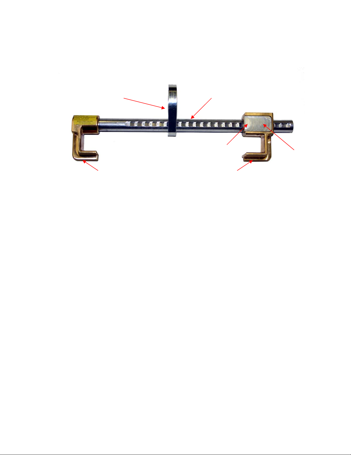
•This device is designed for use on W-shape and other flanged beams.
•Never disable or restrict locking keepers or alter connecting devices in any way.
•Always visually check that each snap hook freely engages D-ring or anchor point and that its keeper is completely
closed.
•Do not attach multiple lanyards together.
•Do not tie knots in lanyards. Do not wrap lanyards around, or allow to come in contact with, sharp, rough edges or
small diameter structural members.
•The use of a shock absorbing lanyard or self-retracting lifeline is required for fall protection applications.
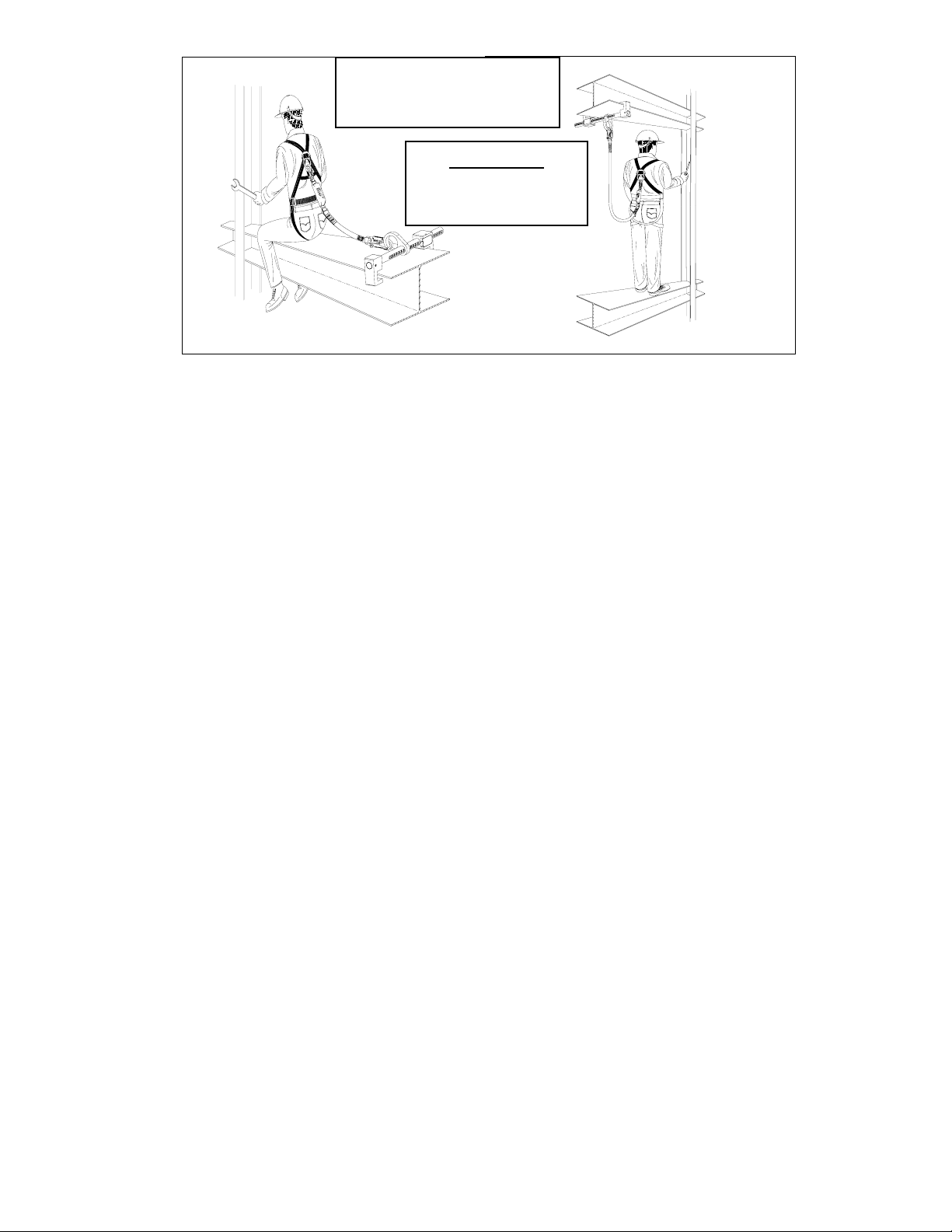
•Whenever possible, the ShadowLite™ beam anchor should be positioned to limit the worker’s free-fall distance to six
feet or less. When the only available beam is at the worker’s feet, the free-fall must be kept to a maximum of twelve
feet and the personal fall arrest forces must be kept to a maximum of 1800 lbs.
•For applications that require the ShadowLite™ beam anchor to be attached to the beam at the worker’s feet, the Miller
and Titan double pack shock absorbing lanyards must be used. Approved models include the Miller SofStop Max,
BackBiter Max, Titan X2 Lanyard and Titan X2 T-BAK.
•Allow sufficient clearance in the event of a free fall. NOTE: Shock absorbers may elongate up to 3-1/2 feet upon
activation.
•Never use a steel cable lanyard for fall arrest unless used in conjunction with a shock absorber.
•Never use natural materials (manila, cotton, etc.) as part of a fall protection system.
•Do not tie-off onto an object which is not compatible with lanyard snap hooks.
•Make sure snap hook is positioned so that its keeper is never load bearing.

B. SYSTEM COMPATIBILITY
The Miller model ShadowLite™ beam anchor is designed for use with Miller approved components
only. Substitution or replacement with non-approved components will endanger system compatibility and may
affect the reliability and safety of the total system.
II. INSTALLATION
Before installation of this equipment, carefully inspect to assure that it is in useable condition.
Check for missing or damaged parts. Consult the inspection section for further details.
1. Locate and identify a compatible structural beam, capable of withstanding a 5,000 lb. static load, or that
meets OSHA 1926.502 requirements for a safety factor of two.
2. Press in on the RATCHET RELEASE BUTTON and slide the ADJUSTABLE FOOT out to its endpoint
(Furthest away from the FIXED FOOT). Release the button.
3. Place the beam anchor over the beam and slide the ADJUSTABLE FOOT back towards the FIXED FOOT
until both are in contact with opposite sides of the beam’s flange.
4. Pull back slightly on the ADJUSTABLE FOOT to seat the RATCHET RELEASE BUTTON in the next
available ratchet slot. The top face of the button should be approximately flush/parallel to the outer face of
the ADJUSTABLE FOOT when properly engaged in the ratchet slot of the SUPPORT SHAFT.
5. Finally: Grab onto opposite ends of the ShadowLite™ beam anchor and make certain that it cannot be
removed from the beam by twisting or rocking.
Removal: Repeat Step 2 of the INSTALLATION before lifting the unit off of the beam.
CONNECTOR RATCHETING SUPPORT SHAFT
PRESS HERE
TO ACTUATE
FIXED FOOT ADJUSTABLE FOOT
RATCHET
RELEASE
BUTTON

TYPICAL WORK-LEVEL AND OVERHEAD INSTALLATIONS
III. TRAINING
It is the responsibility of the user, and the purchaser, of this equipment to assure that they are
familiar with these instructions and are trained in the proper use, installation, maintenance and limitations of
this product. Training should be conducted periodically and without exposing the trainee to a fall hazard.
IV. INSPECTION
The Miller ShadowLite™ beam anchor is designed for today’s rugged work environments. To
maintain the service life and high performance, the beam anchor should be inspected frequently. Inspect the
unit thoroughly before each use. Regular inspection by a competent person for wear, damage or corrosion
should be a part of your safety program. Inspect your equipment daily and replace it if any of the defective
conditions explained in this manual are found.
When inspecting, check for physical damage, wear, and corrosion. Also check the anchorage
connector and components for damage, cracks, wear, corrosion, or malfunctioning items.
Confirm proper operation/engagement of the ratchet mechanism by sliding the ADJUSTABLE
FOOT back and forth a few times and noting proper operation of the RATCHET RELEASE BUTTON. The
button is spring-loaded and should engage each successive ratchet pocket positively and securely. Dirt and
debris that has become lodged in the ratchet slots of the support shaft, or under the RATCHET RELEASE
BUTTON itself, will prevent safe operation of the unit. See Section V. Maintenance for cleaning details.
A qualified person trained in inspection should keep a log of all inspection dates for this system.
WARNING: Failure of the Ratchet Button Spring will render the Unit
UNSAFE FOR USE!
If inspection reveals a defect in condition or operation
REMOVE THE UNIT FROM SERVICE IMMEDIATELY!
V. MAINTENANCE
A. SERVICING
Servicing must only be carried out by Miller Fall Protection. Only original Miller
replacement parts are approved for use in this device. Contact your Miller distributor or the Miller
Fall Protection Customer Service Department at 1-800-873-5242 if you have any questions.
Note: Beam ends are shown as
an open cross section to better
illustrate proper mounting.
WARNING
Do not mount to
open ended beams.

B. CLEANING/STORAGE
Basic care of all Miller Fall Protection safety equipment will prolong its durable life and
contribute toward the performance of its vital safety function. Proper storage and maintenance
after use are as important as cleansing the equipment of dirt, corrosives, or contaminants. Storage
areas should be clean, dry and free of exposure to fumes or corrosive elements.
Clean the ratchet support shaft slots regularly with a stiff-bristled brush or with compressed
air to keep the shaft and release button free from dirt and debris. Wipe off all surface dirt with a
sponge dampened in plain water or a mild solution of water and commercial soap or detergent.
Then wipe dry with a clean cloth. Hang or blow the unit off with compressed air to dry.
VI. SPECIFICATIONS
A. DIMENSIONS
Overall Dimensions (Excluding Connector): 17 ¼” x 3 ¾”x 1 ¾” (440x95x45mm)
MIN-MAX Beam Flange Width: 3”-14” (75-360mm)
MAX Beam Flange Thickness: 1.25” (33mm)
Weight: 4.28 Lbs. (1.94 Kg)
B. MATERIALS
Clamping Feet: Bronze
Support Shaft: 6061 T6 Aluminum
Connector: 6061 T6 Aluminum
Ratchet Spring: Stainless Steel
Assembly Hardware: Zinc Plated Steel
C. PERFORMANCE
Static Tensile Strength (all directions) 5000 Lbs. (2268 Kg) Minimum
D. REGULATORY COMPLIANCE
OSHA 1926.502
ANSI Z359.1 and A10.32-2004
This manual suits for next models
1
Table of contents
Other Miller Safety Equipment manuals