Minimotors DUALTRON THUNDER II User manual

PERSONAL MOBILITY
User Manual

Dualtron Thunder II user manual contents
This manual contains importantinformation to help you to useyour product more
safely. For safe use, it is marked as 'Danger', ‘Caution’and 'Warning' depending
on thedegree of danger and the meaning is as below.
Danger: Indicates a hazardous situation that could be a result of serious injury.
01. General safety guidelines and restrictions ·························································
04
02. Product structure··································································································
06
03. Nameof each part ·································································································
07
04. Productcomponents ····························································································
08
05. How to use the product·························································································
09
06. How to use the instrument panel ··········································································
12
07. LED BARfuntions····································································································
15
08. How to use the charger correctly··········································································
16
09. Safetyprecautions forLithium-ion battery···························································
17
10. Safetyguidelines before driving·············································································
18
11. Maintenance············································································································
19
12. ···························································································
Productspecifications
22
Before Reading Manual
Warning: Indicates a potentially hazardous situation thatcould be a resultin light injury.
Caution: Indicates a potentially hazardous situation that could be a result in serious injury.
Danger
Warning
Caution

04 Dualtron Thunder II User Manual Dualtron Thunder II User Manual 05
L
초보자
급제동 금지
11. Safety warning when lifting the product
If the product is lifted by holding only the handle, there is a possibility that
the product may be damaged due to deformation of the folding part due to
load or movement of the product. When lifting the product, be sure to hold
the product's body (footrest) with one hand and hold the handle with the
otherhand so that you do notget hurt in your back or knees.
2) Precaution before driving
1. Night driving should be avoided in any case, besure to wearhelmets andother guards (knees,
elbows,hands, upperbody, etc.) and drivesafely.
2. Select the mode that suits you and drive. In order to cope with the sudden situation, exercise
to slow down tohold the brakeat all times.
3. When turning left / right, slow down to avoid danger of overturning or slipping., And then
slowlyturn safely.
4. To go to backward, it is safe if you getting off from the productafter stopping before moving.
5. It is prohibited to use in a slippery place, a crowded place, a steep slope, roads with a risk of
accident,uneven road.
6. When crossing a pedestrian crossing, get off from the product for pedestrian safety.
7. Do not drive in a threat any other means of transport, such as animals, pedestrians, bicycles,
motorcycles, cars, etc.
8. If you pass the speed bumps and obstacles, be
sure to slow down.
9. When decelerating or braking, do not stop with
using foot, but stop with using brake appropriately.
10. Be careful that there is a risk of burns due to heat
from motor and brake (especially disk rotor) after
driving.
11. It is prohibited to drive with all the way by holding
thehandlewith one hand.
12. Do not ride ordrive when the kick stand is down.
L
초보자
급제동 금지
10. Do not drive onsteepslopes
Acceptable gradeabilityis different for each product. Excessive hill roads
exceeding the specification may cause damage to the product(parts) due
to temperature cut, overcurrent or low voltage cut, which may cause the
product to malfunction.
관계법 준수
L
초보자
급제동 금지
12. Be sure to wear safety equipment
For the safety of passengers, be sure to wear a full face helmet and the
other protective gear(knee, elbow, hand, upper body) and do not wear shoes
such as slippers, high hillsthat interfere with driving.
Before Reading Manual
1) General safety guidelines and restrictions
Please read this manual carefully
before using this product
관계법 준수
L
초보자
관계법 준수
L
초보자
1. Be careful of water!
This product and componentsare not waterproof. Don’t let the water get into
theproductand components.
*Never useit, if theroad is wet dueto the rain, snow, hailstone.
*If you wash orspread water to electric devices, it can result in malfunction orfire.
2. Beware of folding and spinning parts!
If parts of the body, as a finger or hair, get caught in the spinning or folding
parts of the product, this maylead to severe injuries. Pleasebecareful.
관계법 준수
L
초보자
5. Don’t tune by yourself
Do not open or tune the electric parts (battery, controller or motor
system.
관계법 준수
7.
Beginnersand seniors are encouragedto use at low speed
Beginners who are not accustomed to use the product, seniors and others
shouldavoid high speedmode driving and recommend low speed driving.
In addition,please useafter practice how to ride safely in a wide place.
관계법 준수
L
초보자
3. No acrobatics
Stunts and jumps such as jumping and dropping are prohibited as they can
cause a great impact on the product and can cause of malfunction and
accidents.
4.No companion boarding
This product is intended for one adult only, so children,infants, or two people
are prohibited from boarding.
L
초보자
6.No companion boarding
Unlicensed, driving after drinking, loading cargo on the scooter is prohibited.
(More than bike or bicycle license is required) Please comply with the Road
Traffic.Act and related laws and regulations according to theplaceof use.
* Even if theit is within the warrantyperiod,you maybe liableforanyaccidentcaused by anyof thefollowingcauses.
관계법준수
L
초보자
8. Do not sudden brake withfront brake
If there is a risk of overturning, sudden deceleration should be done safely.
Do not apply any unusual behaviors or artificial forces, such as stopping with
yourfeet.
L
초보자
급제동 금지
9. Do not accelerate downhill
Slow down at downhill. When reducing the speed, to prevent brake
overheat, use the brakes properly to reduce the heat on the disk with
proper brakeuse.
L
초보자
급제동 금지
Caution
04 Dualtron Thunder II User Manual Dualtron Thunder II User Manual 05

handle folding fixingpart
EYE throttle LCD
instrument panel Index finder
throttle(Accellerator)
Switch button collection
Brake lever
(+Electronic brake)
Handlebar fixing
QR lever
Brake lever
(+Electronic brake)
Body frame
Electric wiring diagram
Product size
Handle
1267mm
* Errors may occur dependingon the measurement method.
1208mm
Handle width
609mm
Footrest width317mm
Unfolded
Handlestem
Main power
switch
Bottom
mood lamp
Rear Arm light
Front
Arm light
Rear fender
Handlefolding locking part
QR lever
Horn
Brake&warning light
Charging port
Front lamp
locking slide
Handlepost(Steering tube) LED bar
Frontsuspension
Front fender
F&R 11” wide tubeless tire
(NO FLAT TIRE)
Front motorRear motor
Auxiliary battery
connecting port
Nameof each partProduct structure
Light mount bar(Option)
06 Dualtron Thunder II User Manual Dualtron Thunder II User Manual 07
1
1
2
2
3
3
4
4
D D
C C
B B
A A
Title
Number RevisionSize
A4
Red tail light / brake light
ON
OFF
Front drive switch
E
Brown
Light brown
CO
2
1
3
4
5
6
1
2
3
4
5
6
2
1
25km/h speed limit interface
1
2
1
2
1
2
1
2
2
1
2
1
2
1
2
1
M
Rear motor
M
Front motor
Blue ground light
Blue ground light
1
2
1
2
2
1
2
1
DT-THUNDER type DC brushless front motor controller (A)
2
1
2
1
1
2
1
2
—
+
—
+
Yellow LED warning light
2
1 1
2
DT-THUNDER type DC brushless rear motor controller (B)
ON
OFF
W
Blue
Green
arning light switch
1
2
3
4
5
6
2
1
3
4
5
6
12V5A
OUT+
IN+
IN-
OUT-
DC-DC
V+
JS
RR+
LF+
LR+
RF
+
V-
LF-
LR-
RF-
RR-
L
R
SC
Steering /
warning LED
controller
Steering / warning LED controller
OFF
L
R
Turn signal switch
2
1
3
1
2
3
J5
J4
1
2
2
1
J7
J8
2
1
3
88888
88
KM/H
100%
LCD instrument
Built-in
battery
battery
External
Internal/external power transfer switch
2
31
3-hole charging port-1
2
31
3-hole charging port-2
72Vlithium battery pack
1
23
4
4-hole external battery interface
*3
ON
OFF
Driving light main switch
JRed 1
J
Orange
Red
2
Left/right brake switch
2
1
2
1 1
2
1
2
+
GND
D
+
GND
D
RB
G
RB
G
RB
G
RB
G
D
12V
GND
WS2811
WS2811
vertical pole Left RGB LED
RB
G
RB
G
RB
G
RB
G
D
12V
GND
WS2811
WS2811
vertical pole Right RGB LED
V+
V-
DI
1
2
3
RB
G
RB
G
RB
G
RB
G
Front Right Arm RGB LED
RB
G
RB
G
RB
G
RB
G
Front RGB LED
V-
V+
GRB
GRB
DI
U-
U+
OUT
GRB
GRB
Connection panel RGB LED
1
2
2
1
3
BUS LED Controller
BUS LED Controller
RB
G
RB
G
RB
G
RB
G
Rear right arm RGB LED
RB
G
RB
G
RB
G
RB
G
Rear left arm lamp
V+
V-
DI
RB
G
RB
G
RB
G
RB
G
Side cover left RGB LED
RB
G
RB
G
RB
G
RB
G
side cover right RGB LED
V+
V-
DI
V+
V-
DI
V+
V-
DI
GND
12V
white
white
white
Driving Lights
Driving Lights
Driving Lights
Driving Lights
Driving Lights
GND
12V
white
white
white
Tail brake light
1
2
1
2
2
11
2
+
—
Horn
Black Red
Inside the switch
Inside the switch
Inside the switch
Yellow
Horn switch
2
1
1
2
J6
2
1
1
2
J3
1
2
1
2
2
1
2
1
(1)
Step1: Open the rubber deck
until the red line as shown in
the picture.
Step2: Cut it along the groove
that under the rubber deck.
(Need to open the rubber deck)
Step3: Install the damber.Attach
the bracket to the position where
cut the rubber on step2. Then
install the damperas picture shows.
(2)
(3)
Damper Installation Steps
(Optional part)
Tail light

How to usetheproductProduct components
Charger
Basic tool
Main body
LED Remote
control
Checking the components inside of the box
Top : Default battery charger(1.7A),Default tool, User manual,Remote control
Bottom : Body(Lithum battery included)
Assemblingof the instrument
panel, brake
-Locate the instrument panel and tighten
the fixing bolts.
-Adjust the position of the brake and
tighten the fixing bolts with a 5mm hexagon
wrench.
Make a note of the serial number.
The serial number
can be usedto check
information such as date
of purchase, warranty
period, etc., and product
information can be
checked even if the
product is lostorstolen.
(May vary dependingon
branch officesituation.)
Ejecting the product
Do nothold the handlebar onlywhen lifting the
product from the box.
Please be careful that the fixing slideof thefolding
part may be damaged, and a safety accident such
as a part of the bodymay becaught.
Therefore, when lifting the product, it is
necessary to raise the handlebar first, and then
slowly lift the body (deck) of theproduct with
both hands and do not damagethe folding part
Caution
1) Productun folding
3. Handlebar unfolding 4.Lockingthe handle
QR lever
Locking slide
locking slide
QR lever
1. Raise the handle post(Steering tube)2. Locking the folding parts
QR lever
Finishingscrew
Lockingslide
Tighten the finishingscrew properly to
lock the QRlever so that the locking
slideis firmly fixed in any direction, and
check forlooseness duringuse.
Release theQRlever, raise the locking
slide upwards, raise the handle post,
then lower the locking slide downward.
Loosen theQRlever, pull the locking
slide inward and raise thehandlebar,
then close theQRlever and tighten the
set screw.
Place the lockingslide up to thesafety
line and lock itso thatit is firmlyfixed with
the QRlever. Always check forlooseness
duringuse.
08 Dualtron Thunder II User Manual Dualtron Thunder II User Manual 09

Tip Step3
How to use the product
2) How to start
After tilting the kickstand, find a stable
position on the footrest and then hold the
handle grip comfortably.
Step3. Stance for driving
Acceleration can be performed by using
the throttle of the instrument panel while
driving, and the deceleration or stop can
be performed by holding the brakes on the
handle.
Step4. Acceleration and deceleration
Rear fender
Side stand
Brake
When turning on the product, you can start
driving by turning on the main power switch
first (when using the built-in battery) and
turning on the power of the LCD panel. When
driving is finished, turn off the LCD panel and
turn off the main power.
*The powerof theinstrument panel will turn off
automatically after a few minutes of inactivity.
At this time, the LED lamp is also turned off, so
turn it off with the LED lamp button when you
turn it on again, and turn off the main power
switch afteruse.
Step1. Turningon the main switch
Press the POWER button on the instrument
panel for 2 seconds to turn on the instrument
panel. You can set the start mode, cruise
mode,electronic brake, and ABS function..
Step2. Turningon the instrumentpanel
Before driving, be sure to check the folding part, the handle part, the part where the
main fixing part of the product
is fastened well. And check the position of the fixing slide,
the QR lever locking status and thefolding part fixing status.
Throttle malfunctioncaution
Regardless of whether the throttle is operated or not, the motor sensor may continue to
operate, causing malfunctions such as sudden acceleration. In this case, holding the brake
lever to cancel the operation. This phenomenon may be caused by corrosion of the throttling,
immersion of the throttle, disconnection of the magnet, broken off levers, and breakage of
the spring. Do not bouncethe throttle lever strongly.
Caution
3) How to stop
Step1 Step2
Be sure to use the rear brake first for
decelerating when stopping while driving.
For safe stop, itis necessary to practice slow
down after deceleration with rear brake.
Always use the front and rear brake
levers together to stop smoothly and
safely after decelerating with the rear
brake.
Rear brake use
Driving mode selection
Front brake use
Step4
Set the use and strength of the electronic
brake among the detailed functions of the
instrument panel before driving. When the
brake lever works, the electronic brake works
together to increase the brakingforce.
Deceleration and braking using
electric brake
•For safe braking, check whether the brake lever and disc caliper connection (wire damage, external breakage, etc.) are
damaged before and after driving, and check brake wear and looseness of brake inner core(Inner wire). In the case of
hydraulicbrakes, it is alsonecessary tocheckthe oilleakage or deficiencyandalwayscheck thatthebraking forceissufficient.
•Due to various factors such as road surface condition and speed, it may not be possible to stop when brake is operated as
expected. The electronic brake and ABS functions are auxiliary functions to further increase the braking force and used. The
user should understand the function and expect theoperation timing when use this function.
Check for safe braking
Tip
1. Fold handlebar and steering tube
Folding lock
After folding thehandle bar, unscrew
the QRlever outward and lay the
steering tubedown whileraising the
fixed slide.
When thesteering tube is folded, it is fixed
by using thelocking slideand QR lever,
then itis easy to movebyattaching the
handle with the folding lock device.
2.Fixing the folding part
Finishing
screw
QR leverLocking slide
Steeringtube
4) Product folding
function off function on
Horn
ECO/Turbo model
Emergency light
Turning light Main light switch
Not
press press
Switch button collection:
One button turns on/off the
lights of the whole Thunder II.
10 Dualtron Thunder II User Manual Dualtron Thunder II User Manual 11

00
00 : 00
Km/h 3
TIME
98
%
PAS
E
Y
E
00
00 : 00
Km/h
VOL
3
TRIP O D O DS T TIME C HA
98
%
PAS
E
Y
E
PA
0
Km/h
SET
98
%
E
Y
E
PA
3
Km/h
SET
98
%
E
Y
E
PA
5
Km/h
SET
98
%
E
Y
E
P3
0
Km/h 3
SET
98
%
PAS
E
Y
E
88
98
%
00 : 0088888
Km/h
VOL
TRIP O D O D ST T IME C HA
SET RPM O FF
PAS
Mp/h 8
[ M ]
⑥
⑦
⑨
①②③④ ⑤
⑧
P
O
W
E
R
M
O
D
E
P
O
W
E
R
E
Y
E
M
O
D
E
00
00 : 00
Km/h 3
TIME
98
%
PAS
00
00 : 00
Km/h
VOL
3
TRIP ODO D ST TIME CHA
98
%
PAS
E
Y
E
P3
0
Km/h 3
SET
98
%
PAS
E
Y
E
88
98
%
00 : 0088888
Km/h
VOL
TRIP O D O D ST TIME C HA
SET RPM O FF
PAS
Mp/h 8
[ M ]
⑥
⑦
⑨
①②③④ ⑤
⑧
P
O
W
E
R
M
O
D
E
P
O
W
E
R
E
Y
E
M
O
D
E
00
00 : 00
Km/h 3
TIME
98
%
PAS
E
Y
E
00
00 : 00
Km/h
VOL
3
TRIP O D O D ST TIME C HA
98
%
PAS
E
Y
E
PA
Km/h
98
E
Y
E
PA
Km/h
98
E
Y
E
PA
Km/h
98
P3
0
Km/h 3
SET
98
%
PAS
E
Y
E
88
98
%
00 : 0088888
Km/h
VOL
TRIP O D O D ST TIME C HA
SET RPM O FF
PAS
Mp/h 8
[ M ]
⑥
⑦
⑨
①②③④ ⑤
⑧
P
O
W
E
R
M
O
D
E
00
00 : 00
Km/h
VOL
3
TRIP O D O D ST TIME C HA
P0
00 : 00
Km/h
3
SINCE 1999
P3
0
Km/h
SINCE 1999
MINIMOTORS
98
%
TRIP O D O D ST T IME C HA
SET RPM O FF
SINCE 1999
MINIMOTORS
98
%
How to usethe instrument panel Caution
SpeedSpeed step power button
Accelerator
index finger
throttle
Speed unit
Battery balance
Driving time
modebutton
While the instrument panel is on, press to set the speed step. The setting is completed when the
selected speed step value is selected.
1) Speed step settingCan adjust with button.
P
O
W
E
R
E
Y
E
M
O
D
E
00
00 : 00
Km/h 3
TIME
98
%
PAS
E
Y
E
00
00 : 00
Km/h
VOL
3
TRIP O D O D ST TIME C HA
98
%
PAS
E
Y
E
PA
0
Km/h
SET
98
%
E
Y
E
PA
3
Km/h
SET
98
%
E
Y
E
PA
5
Km/h
SET
98
%
E
Y
E
P3
0
Km/h 3
SET
98
%
PAS
E
Y
E
88
98
%
00 : 0088888
Km/h
VOL
TRIP O D O D ST TIME C HA
SET RPM O FF
PAS
Mp/h 8
[ M ]
⑥
⑦
⑨
①②③④ ⑤
⑧
P
O
W
E
R
M
O
D
E
P
O
W
E
R
E
Y
E
M
O
D
E
00
00 : 00
Km/h 3
TIME
98
%
PAS
E
Y
E
00
00 : 00
Km/h
VOL
3
TRIP O D O D ST TIME C HA
98
%
PAS
E
Y
E
PA
0
Km/h
SET
98
%
E
Y
E
PA
3
Km/h
SET
98
%
E
Y
E
PA
5
Km/h
SET
98
%
E
Y
E
P3
0
Km/h 3
SET
98
%
PAS
E
Y
E
88
98
%
00 : 0088888
Km/h
VOL
TRIP O D O D ST TIME C HA
SET RPM O FF
PAS
Mp/h 8
[ M ]
⑥
⑦
⑨
①②③④ ⑤
⑧
P
O
W
E
R
M
O
D
E
2) Functions and settings for each main screen
P
O
W
E
R
E
Y
E
M
O
D
E
00
00 : 00
Km/h 3
TIME
98
%
PAS
E
Y
E
00
00 : 00
Km/h
VOL
3
TRIP O D O D ST TIME C HA
98
%
PAS
E
Y
E
PA
0
Km/h
SET
98
%
E
Y
E
PA
3
Km/h
SET
98
%
E
Y
E
PA
5
Km/h
SET
98
%
E
Y
E
P3
0
Km/h 3
SET
98
%
PAS
E
Y
E
88
98
%
00 : 0088888
Km/h
VOL
TRIP O D O D ST TIME C HA
SET RPM O FF
PAS
Mp/h 8
[ M ]
⑥
⑦
⑨
①②③④ ⑤
⑧
P
O
W
E
R
mode Can adjust with button.
* Blinks 3 times per 10 seconds when the remainingbattery power is 10%.
It blinks continuously when the remaining battery power is 0%.
You can change the setting mode by turning on the power of the dashboard
and pressing for 2~3 seconds.
In the setting mode, press once to change the internal setting value
P
O
W
E
R
E
Y
E
M
O
D
E
00
00 : 00
3
TIME
98
%
PAS
E
Y
E
00
00 : 00
3
TRIP O D O D ST TIME C HA
98
%
PAS
P
O
W
E
R
M
O
D
E
P
O
W
E
R
E
Y
E
M
O
D
E
00
00 : 00
Km/h 3
TIME
98
%
PAS
E
Y
E
00
00 : 00
Km/h
VOL
3
TRIP O D O D ST TIME C HA
98
%
PAS
E
Y
E
P3 PAS
E
Y
E
88
VOL PAS
[ M ]
⑥
①②③④ ⑤
P
O
W
E
R
3) Instrument paneldetailed function
ModeDiscription
TRIPCurrentmileage(Press and holdmode
button to reset to '0')
ODOAccumulated mileage
CHA Not use
VOL Current voltage
TIMEDrived time
* If you change the default setting values P0 (11), P1 (72), P2 (15), P3 (0),
correctinformation will not be displayed.
Setting mode
Setting value
(1) The start of the cruise function
Select the Cruise function section of the dashboard as 'Settings' and
set the throttle to the same Acceleration.The cruise functionwill start.
(2) End of cruise function
When you hold and releasethebrake while cruisemodeis in effect, thecruisemode is automaticallyreleased
Precautions when using the cruise function
* In case of cruise function, please ride in a position where brake can be used immediately so that
cruise function is canceledand brakingis possible in preparation for safety situation while driving.
* When switching from dual drive mode to single mode in cruise mode, it is not possible to cancel
cruise mode by usingthrottle and it is only possible to releaseby braking.
4) Features of cruise mode (automaticdriving)
1. Displayngspeed unitselection - P4: 0 (Km/h),1 (mp/h)
2.Start methodselection - P5: 0( Acceleration start), 1 (Kick start)
3.Cruisemodeselection - P6: 0(Off), 1(On)
4. Slow start- P7: 0 (Slow start off: Power start)~ 5 (Slow start)
5. Battery savemode - P9: 1 (MAX SAVE),2 (MID SAVE), 3 (NO SAVE)
6. Electronic brake settingmode - PA: 0 (Electronic brake off) ~ 5 (Strongest)
7. LCD brigntness adjustment - Pb: 0 (Backlight off) ~ 5 (Highest illumination)
8. Auto off time setting - PC: 1 ~ 30 minutes
9. ABS setting - Pd: 0 (OFF), 1 (ON)
The cruise control function allows you to maintain the driving speed automatically. Take
advantageof cruise features
The advantage of being able to reduce fatigue when traveling long distances and to increase
mileage of driving due to constant speed driving.
P0 P 1 P2 P3 P4
P9P5 P6 P8
P7
PA PCPb
Pb
P0
11(Fixed)
Start method
0(Acceleration start),
1(Kick start)
Slow start
0(Off:Power
start~5(Slow start)
Max output
5~100%
(User adjust)
Electronic brake power
0(Off)~5(Powerful)
LCD brightness control
0(Back light off)~5(Brightest)
Auto off time setting
1~30 minutes
Cruise mode
0(OFF)
1(ON)
72(Fixed) 15(Fixed)
Caution
Battery save
1(MAX SAVE)
2(MIDSAVE)
3(NO SAVE)
ABSsetting
0(OFF),1(ON)
0(Fixed)Speed unit
0(Km/h), 1(mp/h)
급제동금지
급제동 금지
12 Dualtron Thunder II User Manual Dualtron Thunder II User Manual 13

ABS OFF
PA
0
Km/h
SET
98
%
E
Y
E
PA
3
Km/h
SET
98
%
E
Y
E
PA
5
Km/h
SET
98
%
E
Y
E
P3
0
Km/h 3
SET
98
%
PAS
E
Y
E
88
98
%
00 : 0088888
Km/h
VOL
TRIP O D O D ST T IME CHA
SET RPM O FF
PAS
Mp/h 8
[ M ]
⑥
⑦
⑨
①②③④ ⑤
⑧
0
Km/h
SET
98
%
E
Y
E
1
Km/h
SET
98
%
Pb
P0
Pb
P0
E
Y
E
0
Km/h
SET
98
%
1
Km/h
SET
98
%
Pb
P0
Pb
P0
E
Y
E
PA
0
Km/h
SET
98
%
PA
3
Km/h
SET
98
%
E
Y
E
PA
5
Km/h
SET
98
%
E
Y
E
P3
0
Km/h 3
SET
98
%
PAS
E
Y
E
88
98
%
00 : 0088888
Km/h
VOL
TRIP O D O D ST T IME CHA
SET RPM O FF
PAS
Mp/h 8
[ M ]
⑥
⑦
⑨
①②③④ ⑤
⑧
E
Y
E
PA
0
Km/h
SET
98
%
E
Y
E
PA
3
Km/h
SET
98
%
PA
5
Km/h
SET
98
%
E
Y
E
P3
0
Km/h 3
SET
98
%
PAS
E
Y
E
88
98
%
00 : 0088888
Km/h
VOL
TRIP O D O D ST T IME CHA
SET RPM O FF
PAS
Mp/h 8
[ M ]
⑥
⑦
⑨
①②③④ ⑤
⑧
00
00 : 00
3
TRIP O D O D ST TIME C HA
98
%
E
Y
E
PA
0
Km/h
SET
98
%
E
Y
E
PA
3
Km/h
SET
98
%
E
Y
E
PA
5
Km/h
SET
98
%
E
Y
E
P3
0
Km/h 3
SET
98
%
PAS
88
98
%
00 : 0088888
Km/h
VOL
TRIP ODO DST TIME CHA
SET RPM OFF
PAS
Mp/h 8
[ M ] ⑥
⑦
⑨
①②③④⑤
⑧
ABS ON
How to use the instrument panel LED BAR funtions
5) Setting of Electronic brake
6) ABS functionsetting guide
* Precautions when usingelectronic brake immediately after full battery charge
The electronic brakes do notoperatewhen the batteryis fully charged, so besureto
checkandoperate this device. When the batteryruns out,the electronicbrake will operate
normally.
* Precautionswhen using the ABS function
ABS has the advantage of being able to stop attheshortest braking distance that can be
obtained from the tires and road conditions. However, due to the principle of repeatedly
holding andreleasing the brakeseveral times in a second, a lot of vibration occurs in the
motor and the body. Repetitive vibration caused by this may causefrequent loosening of
the motor, rim, fixing partand body fixing bolt.
* ABS brake is an abbreviation of Anti-Lock Brake System. It uses the principle that maximum static
friction force is larger than kinetic friction, so that braking distance (distance from breaking to
stopping) is shorter than that of normal brake. It has the advantage that the vehicle does not slip
well when wheel is rotating.andit is a brake assist system that can stop more safely without wheel
lockand slip.
(1) ABS function ON
Set the ABS function part Pdof the dashboard to 1.
(2) ABS function OFF
Set the ABS function part Pdof the dashboard to 0.
* Pd - When the ABS function is ON, the PA -
electronic brakefunction is canceled.
All electric motorcycles are subject to sudden braking, causing the wheels to stop spinning. As a result,
the slip of tire causes the driver to fall down, which can cause accidents. This product is equipped with ABS
brake function to hold the tire lock, enabling more secure braking.
Electronic brake off Moderate intensity Maximum intensity
Caution
Caution
Displayed when the brake
leveris operated
7) Self-diagnosis through dashboard
Fault typeDiagnosis Solution
System error * If the error information
appears, immediately stop
using the product and take
the scooter to the service
center beforeuse. Excessive
use can result in damage
to the product and safety
accidents.
Motor error
Accelerator error
Controller error
None
* Thenumber is displayedwhen the cruisefunction is executedat a
constantspeed.
* Thenumber is displayedwhen the brake lever is operated. (When
theindicatorlights,the accelerator does notoperate.)
⑥
⑦ ⑨
①
②
④
⑤
⑧
⑥
⑦ ⑨
①
②
③
④
⑤
⑧
The LED remote control is infrared. Please aim at the bottom of the right LED bar.
Remote control functions and settings
⑥
⑦ ⑨
①
②
③
④
⑤
⑧
⑥
⑦ ⑨
①
②
③
④
⑤
⑧
⑥
⑦ ⑨
①
②
③
④
⑤
⑧
⑥
⑦ ⑨
①
②
③
④
⑤
⑧
⑥
⑦ ⑨
①
②
③
④
⑤
⑧
W/WW
Flash
Jump
Jump
IC Set
CS
C3
C7
Auto
C16
Pow
er but
ton
Brightness&Light speed Whole white lamp
&Number of lamp beads
control block
Light change mode
slection block
Multicolor light mode
selection block
Brightness&Light speed
&Number of lamp beads
control block:
Multicolor light mode selection block:
When single color light orwhole white light is on, brighter/ darker; when the multicolor light is on, the ligh
runs faster/ the light runs slower. When you press”IC Set” button, you can choose how many lamp beads wor
Press “IC Set” button again to end the setting.
Tip
“C3”, 3 colors of light shine together;“C7”,7 colors of light shine together;“C16”, 16 colors of light shine together
“CS”, single color lightshines.
Remote receiver
The lights will only be
controlled
when you oprate
the remote
towards this place
14 Dualtron Thunder II User Manual Dualtron Thunder II User Manual 15

Lithium
How to use a charger correctly Safety precautions for Lithium battery
2) Basic charging method *Failure of the charger and abnormal conditions can cause
electric shockandfire. Learn thecorrect usage and prevent safety accidents in advance.
* Short-circuit Caution:
Be careful notto short-circuit thebatterybecauseshort-circuiting of thebattery is verydangerous.
* Overcurrent Note: The battery of this product is designed to automatically shut off the
power supply to protect the battery when theover current is over100A.
* Low Voltage Caution: The battery of this product is designed to be automatically shutoff when
the voltage drops below 48V. Do not usethe product in thelow voltage state.
5. If the charger lamp does not light,
charger fall, strong external
shock, long time charge, or cable
cover damage, discontinue use
immediately and contact the service
center.
6. Unplug the charger when you are away from
the home for long periods of time.
1.Manufacturers and sellers are not
responsible for any problems
arising from any disassembly,
modification, or mixing with other
chargers.
2. The charger is forbidden to be used
in places subject to high humidity,
heat, flammable materials,
confined spaces, or where there
is no ventilation such as in a car.
3. The charger is not waterproof. It is
thoroughly controlled to prevent
moisture from entering the
charger.
4.Children and pets should not be
allowed to approach the charger
when they come into contact
with them, as they may cause an
electric shock.
7. Use only genuine charger.
8.Do not insert conductors into the charging port.
9. Do not touch the plug for about 10 seconds after unplugging the charger. There is a risk of
electric shock from instantaneous discharge.
10. Do not remove the terminal during charging. Charge the internal circuit of the charger and
cause malfunction.
11. Do not operate the product during charging.
12. Charging terminals should be firmly contacted during charging and should not be used if
terminals are corroded or damaged.
13. When disconnecting the charger from the product, it is safe to hold the terminal without holding thewire.
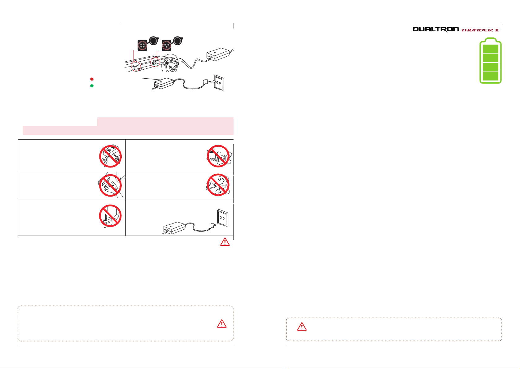
1) Basic charging method
1. Open the chargingport cap and connect
it to the connector of the charger and
connect it to the household outlet.
3. Be sure to close the chargingport cap when driving or storing except when charging.
4. When connecting the connector to the charging port, metallic sparks due to voltage
difference may be splashed, but this is normal
1. Care
Lithium batteries should be protected from direct exposure to children and pets.
2. Performance
①Lithium battery is affected by external temperature. In winter, when
the temperature is low, the performance of the battery is temporarily deteriorated and
themileage and poweroutput is reduced.
②Lithium battery has a characteristic that discharge performance is reduced by more
than 15% when charging / discharging 300 times or more. If usage time is shortened
dueto long usage, it shouldbe replaced with a genuine onethrough the nearest point.
3. Charging
①Lithium battery should be used only with genuine battery and charger
supplied from the manufacturer. Any problems caused by use of battery made by the manufacturer,
mixed use, or using the chargerarenot covered bythe manufacturer.
②Charging thelithium battery with a non-genuine charger may cause malfunction or fire.
③The lithium battery should be charged in a well-ventilated, dry place and around the charger in a
place where there is no inflammablematerial.
④Lithium battery should be charged at 0 ~ 45 ℃and discharged within -10 ~ 60 ℃. Charging or
discharging at a temperature outside this range may cause malfunction, fire or explosion.
⑤In case of moving from cold outside to warm indoor, please charge it after 1 ~ 2 hours. This is to
prevent condensation from occurring insidethe product dueto temperaturedifference.
4. Storage
①Lithium batteries should be kept away from snow, rain and direct sunlight. Do not store or
charge them in a trunkorhot room. Select a dry placeandstoreat room temperature (10 ~ 20 ℃).
②When storing for more than 3 months, charge the remaining battery level to 70 ~ 80% (do not
storefull charge).
5. Trouble symptom, safety
①Lithium battery should be discontinued immediately if it is damaged
or leakage of battery, sour odor, appearance deformation, etc., and contact the place of purchase to
get technical support and service.
②If overheat, smoke or ignition is detected in a product with lithium battery, immediately stop
charging and use, move the product outdoors as soon as possible, and then use a fire extinguisher
to evolve. Do not spray water or immerse the productin order to evolve, which is more dangerous.
③Lithium battery pack has very high energy density, so if you charge the battery for a long time
in case of short-circuit, leakage, bad battery, etc., there is a possibility of ignition. Therefore, you
should avoid charging for a long time without a person, and charging must be done while the person
is aware that the risk of unexpected fire can be avoided.
6. MisuseIf
the lithium battery is short-circuited or the polarity is changed, or if the battery is
impacted, malfunction or fire may result. If you think that the battery has been impacted, you should
stop charging and using it and visit thenearest point for inspection.
7. Water iBattery disassembly, modification and repair are not covered under warranty.
o
the lithium battery. There is a risk of fire or electric shock if the charger is connected while moisture
is present.
8. Caution
Disconnect the battery from the main unit and prohibit recharging, reinstalling, or using
other applications.
9. Disposal
DisposalWhen disposing of the lithium battery, the battery should be separated from the
product at the point of purchase or near the point so that the charge and discharge terminals are not
short-circuited. Disposeof it as industrial waste when disposing of it.
Battery disassembly prohibited
Battery disassembly, modification andrepair arenotcovered under warranty.
Warning
CautionDanger
2. Charging status indicator (Red) Charging
(Green) Charging complete
16 Dualtron Thunder II User Manual Dualtron Thunder II User Manual 17

1. Check throttle and handle
Fatigue failure parts and maintenance parts replacement cycle
DUALTRON THUNDER II
No Parts name
Replacement cycle / km
1SWING ARM
2 HIGHER HINGE
3YEARS / 20,000
3
2YEAR / 10,000
4
STEERING TUBE 3YEARS / 20,000
5
HANDLE STEM 3YEARS / 20,000
3YEARS / 20,000
6
LOCKING SLIDE
7
BATTERY 2YEARS / 20,000
Other chassis
components
If the exterior is
damaged or deformed
CHECK LIST
④
⑤
①
⑥
③
②
Safety guidelines before driving Maintenance
• The brake braking force is sufficient to check the operating condition. If the braking force is significantly
lowered, useit immediately after inspection andaction.
• Check that the brake pad is not worn, that the cable is not loose, that the cable is not
damaged, or thatthere is no leakage in the caseof hydraulic brakes.
• If there is an unusual feeling or noise during operation, check for breakage, wear and
deformation of the inner wire of the brake cable.
• Check that the bolts and nuts of the brake fixing parts are not loose, and that the disc
is not deformed or damaged.
• Operate the accelerator throttle lever about 2 ~ 3 times to check whether it returns
to thehome position.
• Be careful that excessive throttle leaning and manipulation of the throttle can cause
malfunction due to internal parts damage.
• Check the fastening condition and clearanceof the QRlever on the handle.
*If there is a folding clearance,
If there is a folding clearance, itcan be adjusted with a tongue bolt. However, if
you pull ittoo hard, it will become stiff withouta gap, but it maysound'crackling'.
In this case, if you adjust the tune bolt properly, the noise disappears and the
clearance is also adjusted.
If you encounter any of the following situations while driving, stop driving immediately and
contact your nearest branch or service center for proper measures. If you provide pictures and
videos to get accurate diagnosis, professional counselingis available..
●Unusual heating of the motor
●Brake braking status error
●Errormessages on theinstrument cluster
●When the throttle is returned to its original position
* In this case, stop driving immediately.
Danger
●abnormal noise is generated
●Product smoke, ignition, sourodor
●When rain orwetwith water or in a similarsituation
●When other driving is judged to be unreasonable
1) Required checking before use 2) Maintenance and self-maintenance
Electric products can be damaged by various factors. The life span of each part
varies depending on driving habits and driving environment. Parts that exceed the
service life may cause accidents. Let's manage various parts and prevent safety
accidents in advance.
※The rubber inside the rubber suspension is cured as the consumable parts are used, and the
performance of the suspension is slightly reduced because of the reduced elasticity.
①The components and suspension parts of the car swing arm, tires, tubes, wheels, bearings,
headset bearings, discs, brake pads, cables and folding parts, various brackets and other
consumable parts requiring periodic inspection And always check.
2. External damage inspection by driving environment
①Replace parts that may be damaged by external driving environment, such as deformation of
parts, cracks due to compression, and signs of exceeding fine gold or life expectancy.
②If the product is exposed to strong sunlight for a long time, discoloration may occur.
③In case of heavy driving such as normal jumps, slight impacts such as turning, collision, etc.,
when driving frequently or for a long time in a poor road condition or driving for thousands
of kilometers or more, fatigue breakdown phenomena Please check and replace the parts
replacement schedule for each product for safety.
④Fatigue breakdown and maintenance parts may
differ from the example conditions depending
on the driving environment and the operating
conditions. Also check parts other than the
replacement cycle (maintenance parts) at all times to check for any signs of abnormality.
2. Check brake and cable
• Check the front and rear tires for wear and punctures and check the proper air pressure
(45 to 50 psi) for the tire. When the shortage of air is shortened, the possibility of
punctureincreases, so check always.
• It is necessary to judge the replacement time by observing the appearance of the tire
such as tire damage, uneven wear.
3. Check tire pressure and uniaxial condition
• Make sure that the bolts and nuts of all parts of the product are tight and free from
loosening. Check the fastening condition and clearance of the folding and fixing
parts of the handle (QR lever, fixed slide, hinge center bolt, headset nut, swing
arm, etc.)
4.Tightening check such as folding part and handle part
Danger
1. Check the replacement timing of consumable parts
18 Dualtron Thunder II User Manual Dualtron Thunder II User Manual 19

Maintenance
* Metal vibration may occur due to motor vibration, vibration of the brake disc and pad
during the load section that accelerates during driving. (About 15 ~ 30Km, different for
each product)
This is a phenomenon in which all revolutions (fans, automobiles, ships, etc.) are
vibrating at a specific rotational frequency (rpm) rather than the product. However, if
the continuous noise or metal noise is large, there is a possibility that the disk is bent
anddeformed.
* Please note that after running, there is a risk of burns due to the heat on the motor
andbrake(especially disk rotor)side.
* Be careful that the bolts of the motor, rim and motor shaft due to the ABS function
may beloosened.
Important notice3. Causes and countermeasuresof disc brake noise
The disc braking method uses a disc brake method with many
electric kickboards because braking power is good. However,
if you get a sharp hissing sound when you hold the disc brake,
dust or sand particles on the ground will spill out on the surface
of the disc, causing foreign substances to be on the brake pads
or disc surface, or bending due to heat or external impact. At
this time, clean the inner surface of the disc by turning the
wheels with a clean, dry cloth, or straightening thebent discs.
If the above measures are not taken, please visit the nearest branch and take a
safety check. There may be another problem.
Caution
3) Maintenance by self-maintenance
1. Brake adjustment method
If the braking force decreases due to overheating of the oil,
damage of the oil hose, loosening of the brake lever, oil
leakage, etc. after using the brake for a long time on the
downhill road, stop using and use after checking it.
2. Tire replacement method
1. After removing the calipers, remove the motor using 18mm
spanner and disassemble the wheel andmotor fastening bolts.
2. Remove thewind from thetires and press the tires off the wheel.
3. Replace the tires and complete the assembly of the tires in
reverse order. Tighten the assembled tire to fit the body, then
tighten thescrews and bolts.
*caution
●After completing the tire replacement, try a simple test run with the appropriate air pressure (45 to 50
psi).
●When puncture is occurred, it is possible to use repair by using patch seal. Please use the tire while
checking and checking continuously.
4. Variable rubbersuspension system (patent pending) adjustment
Designed by MINI Motors, the world's largest 45-step adjustable (3x3x5) rubber suspension system
allows you to adjust the suspension strength with motor shaft distance (3 steps), arm angle (3 steps),
and rubber cartridge replacement (5 steps).
1. Remove the front fender with a 3mm hex wrench, loosen the 18mm (motor side), 19mm (swing arm
side) nut, and then loosen thenut to remove the suspension arm.
2. Adjust the motor shaft distance, rubber cartridge replacement, and arm length to the desired
suspension strength.
Garageheight
Intermediatestage
Garagelowered
■Motor shaft distance (3 steps): Height
adjustent(by weight)
You can adjusttheheight from thecenter.
■
Rubber Replacement (5th Stage): Replace
Cartridge (Adjust height by weight)
Loosen both nuts with a wrench, loosen 3mm
bolts and remove. Replace the cartridge when it
is missing.
(It can be changed depending on weightand taste)
3. Align both suspension arms to the desired angleand reassembleusing Loctite (screw lock).
20 Dualtron Thunder II User Manual Dualtron Thunder II User Manual 21
It is the first time “NO FLAT TIRE” tire is used on Minimotors scooters.With the
perfect puncture resistance and no need for tire patching, it brings extraordinary
riding experience under any circumstances.
NO FLAT TIRE

MEMO
Product Name DUALTRON THUNDER II Note
Motor
INSTANT PEAK POWERUP TO 10,080WBLDC DUAL HUB MOTOR
Battery type
Li-Ion battery pack
LG 21700,M50T
Battery capacity
72V 40Ah
Charging time (1.4A)
28hr+ When using standard charger(1.4A)
Charging time (2.8A)
14hr+ When using 2 standard chargers(1.4A)
Charging time (6.4A)
6hr+
When using 1 fast charger(5A)&standard
charger(1.4A)
Max mileage
Around 170km
75kgload,25km/hflatroad continuousridingbasis
Max Speed 100km/h
Folding
Handleposttwotouchdoublefolding Patent pending
Gradeability
Around 70% (35°)
Weight,roadcondition,batterystatus,tem-
peraturecanaffecttothegradeability
Max load
120kg
Product weight
Around 47.3kg
Unfolding size
1208 x 609 x 1267mm Length x Width x Height
Folding size
1208 x 317 x 577mm Length x Width x Height
Instrument panel
EYE throttle is applied as the default
option.(Bettery level, TRIP, ODO, Time,
Speed display and mode change.)
Cruise / Electric brake / Auto save
function(3minutes)
Light DC to DC converter is built in(12V 5A output)
Brake
Nutt hydraulic brake+160mm disk
Commonuseforfront andrearwheel
Suspension
45-stepadjustablenewrubbersuspension
9stepvariablesuspensionsystem
+ 5 kindsofrubbercartridgereplaceabledesign
Rubber cartridge normal is applied
basically(Soft, Medium soft, Hard, Medium
hard cartridge is optional/Patent pending)
Tire
11inch wide tubeless / RSC tire
Product material
Frameandhandle:Aviationaluminumforgingalloy,6082-T6,Shaft:SCM440,Covers:Polypropylene
*Thespecification can be changed by manufacturer withoutnotice to improve the quality andsafety forusers.
*The distance can be affected by loaded weight, wind direct (wind speed), road condition, slope
and tire condition.
22 Dualtron Thunder II User Manual Dualtron Thunder II User Manual 23
LED TAIL LIGHT(new design), ARM LIGHT,STEERING
TUBE&SIDE DECK RGB LIGHTS,WARNING LIGHTS,
BRAKE LIGHTS AND BOTTOM MOOD LIGHT

DUALTRON THUNDER II
Electric Scooter
User Manual
Table of contents
Other Minimotors Scooter manuals

Minimotors
Minimotors DUALTRON X-LIMITED User manual

Minimotors
Minimotors DUALTRON X Series User manual

Minimotors
Minimotors SpeedWay V User manual

Minimotors
Minimotors Dualtron Achilleus User manual

Minimotors
Minimotors DUALTRON ULTRA II User manual

Minimotors
Minimotors DUALTRON III User manual

Minimotors
Minimotors DUALTRON mini User manual