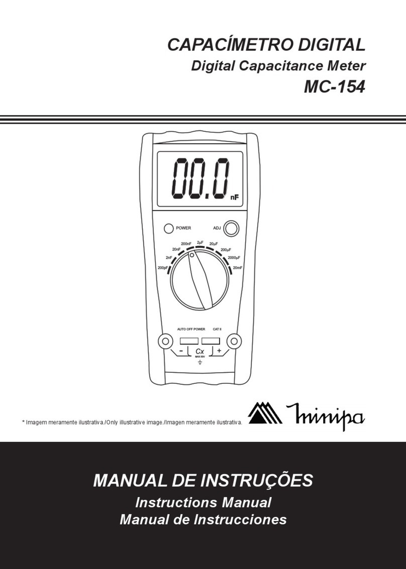
Minipa MC-153 User manual

DIGITAL CAPACITANCE METER
INSTRUCTIONS MANUAL
ManualdeInstrucciones
ManualdeInstruções
*Onlyillustrativeimage./Imagenmeramenteilustrativa./Imagemmeramenteilustrativa.
Capacímetro Digital
MC-153

1
CONTENT
1) GENERAL OVERVIEW ..................................................................... 02
2) FEATURES ........................................................................................ 02
3) TERMS IN THIS MANUAL ................................................................. 03
4) ACCESSORIES ................................................................................. 03
5) FRONT PANEL DESCRIPTION ........................................................ 04
6) OPERATION ...................................................................................... 05
6.1 Measurement Consideration ................................................... 05
6.2 Capacitance Measurement ....................................................... 05
7) MAINTENANCE ................................................................................. 08
7.1 Cleaning .................................................................................... 08
7.2 Battery Replacement ................................................................ 08
7.3 Fuse Replacement .................................................................... 08
8) SPECIFICATIONS ............................................................................. 09
8.1 General Specifications ............................................................. 09
8.2 Electrical Specifications .......................................................... 10
9) WARRANTY ....................................................................................... 11

2
1) GENERAL OVERVIEW
•This capacitance meter is able to measure capacitance of capacitor. It
willnotmeasuretheQfactorofreactivecomponents.Incorrectreadings
can be displayed when trying to measure the capacitance of resistive
loads.
•When measuring capacitance, make sure that the component or circuit
under test is de-energized before make measurements.
•Avoid to short circuit the test leads.
•Instruments used in aggressive environments must be cleaned and
send to calibration periodically.
•Before replace the battery or the fuse, make sure that the meter is
turned off and disconnected from any circuit or component.
•To make measurements, the black test lead must be connected at
negative terminal “-” and the red test lead to positive terminal “+”.
•Before measurements of electrolytic capacitors, make sure that is
fully discharged.
•To guarantee the accuracy of measurement, do not touch the terminals
during the measurement.
•Donotallowthattheinstrumenttobeexposedtohightemperaturesand
the direct incidence of sunlight to avoid the reduction of LCD life.
•At low capacitance measurements we recommend to adjust the zero
reading with the test leads opened before the measurement.
2)FEATURES
•Easy and correct readings.
•High accuracy measurements.
•Internal circuit with high durability and reliability.
•Build-in overload protection.
•Low consumption LCD display and easy to read even in low light
environments.
•Compact and light-weight for easy operation.
•Low battery indication in display.

3
3) TERMS IN THIS MANUAL
WARNING identifies conditions or practices that may result in
serious wounds or even death.
CAUTION identifies conditions and practices that may cause
damage or instrument malfunction.
WARNING
To reduce the risk of fire or electrical shock does not expose this instrument
to rain or high humidity. This instrument was designed to indoor use only.
INTERNATIONALELECTRICALSYMBOLS
Caution! Risk of electrical shock
Caution! Risk of danger
Earth(Grounding)
Double Insulation or Reinforced Insulation
AC - Alternating Current
4)ACCESSORIES
Check if the following items are not missing or damaged:
1. Instructions Manual (1 piece)
2. Test leads (1 pair)
3. Battery (1 piece)
4. MAK-2 Adaptor (1 piece)

4
5) FRONT PANEL DESCRIPTION
WARNING
Turn off the power of circuit under test and discharge all the capacitors
before measurements.
1) LCD Display: The display shows the measurement.
2) Rotary switch: Used to select the measurement range.
3) Zero adjustment key: Adjust the zero in measurements using low
capacitance ranges.
4) Negative input terminal “-”.
5) Positive input terminal “+”.
!

5
6)OPERATION
6.1 Measurement Consideration
1) This capacitance meter was designed to measure capacitance of
capacitors.The meter willnotmeasure “Q” factorofreactive components.
Wrong reading will be displayed when trying to reading the capacitance
of resistors.
2) When components are measured in circuit, turn the circuit off and
discharge all capacitors before connect the test leads.
3) Do not get the test leads close to each other (black & red).
4) Instruments used in aggressive environments, with dust, must be
cleaned periodically.
5) Do not expose the capacitance meter to heat by long time.
6) Before remove the battery cover or open the capacitance meter, check
if the meter is disconnected from the circuit and the rotary switch is in
OFF position.
7) Toall measurements,connect the black test lead tonegative “-” terminal
and the red test lead to positive terminal “+” of capacitor.
6.2 Capacitance Measurement
1) Set the rotary switch to the desired measurement, in accordance with
the value of capacitor to be tested.
2) Zeroindication check: at 200pF, 2pF, 20nFranges, checkifthe indication
is zero. If not adjust it by turning the Zero Adjustment key.
3) Check the polarity when measuring polarized capacitors.
4) Discharge completely the capacitor before measurement, and if the
measurement will be made in circuit, turn off the power supply and
discharge all capacitors before measurements.
5) Connect the test leads black and red to “-” and “+” terminals, and the
alligator jaws to the terminals of component under test. Or utilize MAK-2
adaptor to conect the capacitor to the capacitance meter.

6
6) Make the reading in display. The measurement is displayed with the
corresponding units pF, nF and µF, indicated at the rotary switch. Only
at the 2000µF x10 the reading must be multiplied by 10. If the display
shows the overrange indication (1), select the next upper range. If the
display shows one or more zero at the left of display, select the next
lower range to obtain better resolution.

7
NOTES:
a) If the capacitance value is unknown, start the measurement at 200pF
range,and select the next upper range until that the overrangeindication
is not displayed.
b) A capacitor in short condition will display an overrange indication in all
ranges. A capacitor with low voltage leakage will present overrange
readings or a capacitance value higher than the specified.
c) Lowcapacitance measurements must be executed with short test leads,
to avoid parasite capacitance.
d) Whenusing optional test leads, remember that the test leads introduces
parasite capacitance in measurements. As compensation, the test
leads capacitance can be measured leaving the test leads in open state
and reading the capacitance at the display. Record this reading and
subtract it from the next measurements.
e) Electrolytic capacitors present low accuracy. Do not be surprised if the
reading is higher than the nominal specification at the capacitor, unless
it is a high accuracy capacitor. However, readings lower than the nominal
value of capacitor is unusual.

8
7)MAINTENANCE
7.1 Cleaning
Periodically clean the meter with a soft cloth slightly wet with water or mild
detergent, and take care to not remove the overlay. Do not use abrasives
or solvents, or even alcohol.
7.2 Battery Replacement
Replace the battery when the low battery indicator appears in LCD display.
Replace the battery immediately in order to keep the instrument in normal
operation condition. Follow the instructions below to replace the battery.
a) Check if the instrument is not connected to any circuit. Set the rotary
switch to OFF and remove the test leads from input terminals.
b) Remove the three screws, at the rear side of instrument.
c) Remove the old battery and replace it with a new battery, with the same
specifications.
d) Place the battery cover and the screw.
7.3 Fuse Replacement
When any measurement was not possible, probably the internal fuse
burned out, in this case please follow the steps below to replace the fuse.
a) Check if the instrument is not connected to any circuit. Set the rotary
switch to OFF and remove the test leads from input terminals.
b) Remove the three screws, at the rear side of instrument.

9
c) Remove the four screws from the bottom case and open the instrument
carefully.
d) Replace the fuse with the same type and rating: 5x20mm, 100mA/
250V.
e) Place the bottom case, the screws and the battery cover.
8) SPECIFICATIONS
8.1 General Specifications
LCD Display: Maximum reading of 1999.
Measurements: C (Capacitance).
Ranges: 9 positions, range of measurement (0.1pF to 20000µF).
Zero Adjustment: Manual , ±20pF.
Sampling Time: 0~5 seconds.
Operation Environment: 0°C to 40°C, relative humidity < 80% max.
Overrange Indication: Display shows the last significant digit (1).
Power Supply: One 9V battery (NEDA1604, IEC6F22).
Battery Life: Approx. 200 hours (alkaline battery).
Consumption: 3 to 4mA typical (ranges 200pF to 200µF).
Dimensions: 170(H) x 78(W) x 42(D)mm.
Weight: 240g.

10
8.2 Electrical Specifications
Accuracy: ± (a% reading + b digits), at 23°C ± 5°C, RH < 80%.
Range Accuracy Resolution Test
Frequency Maximum
Indication
200pF ±(0.5%+ 7) 0.1pF 800Hz 199.9pF
2nF
±(0.5%+ 5)
1pF 800Hz 1.999nF
20nF 10pF 800Hz 19.99nF
200nF 100µF 800Hz 199.9nF
2µF 1000µF 800Hz 1.999µF
20µF 0.01µF 80hz 19.99µF
200µF 0.1µF 8Hz 199.9µF
2000µF ±(2.0%+5) 1µF 8Hz 1999µF
20000µF ±(3.0%+10) 10µF 8Hz 1999(x 10)µF
pF = Pico Farad (10-12F)
nF = Nano Farad (10-9F)
µF = Micro Farad (10-6F)
Zero Error: 20pF
Test Voltage: 2.8V RMS maximum
Overload Protection: 0.1A/250V fuse.

11
9)WARRANTY
This instrument was carefully calibrated and inspected. If any failure
occursunder normal use, this product willberepaired according to warranty
conditions and limitations.
WARRANTY
SERIAL Nº MODEL MC-153
1- The warranty period is 12 (twelve) months and begins on the date
of purchase.
2- It will be repaired free of charge in following cases:
A) Manufacturingdefectsordamagesoccurredundernormaluseof
instrument within the warranty period.
B) The services to correct the failure will be done only in authorized
service center or personal will be allowed to fix this product.
C) If product is purchased through a Minipa’s authorized dealer.
3- Warranty will be void in case:
A) It has been misused, altered, neglected or damaged by accident
or abnormal conditions of operation or handling.
B) Theinstrumentshowsviolationsbyanonauthorizedrepaircenter.
4- This warranty does not apply to fuses, dry cells, batteries and
accessories as test leads, carrying case, thermocouple, etc.
5- Forinstrument withsoftware,Minipa assumesresponsibilitythat the
software will operate in accordance with its functional specifications
for 90 days. Minipa will not guarantee that the software will be error
free or operate without interruption.
6- Minipaassumesnorisk fordamageintransitortransportationcosts.
7- Warranty will be valid only after the registration of this
certificate.
Name:
Address: City:
State: Phone:
Sales Voucher N°: Date:
Serial N°:
Sales Agent Name:

12
Warranty Certificate Registration Procedures
The registration can be made by following ways:
-Mail: Send a copy of warranty certificate correctly filled to the
following address.
Minipa Indústria e Comércio Ltda.
Att: Serviço de Atendimento ao Cliente
Alameda dos Tupinás, 33 - Planalto Paulista
CEP: 04069-000 - São Paulo - SP
- Fax: Send a copy of warranty certificate correctly filled by fax
number0xx11-5071-2679.
- e-mail: Scanning this formand attach to your e-mail. Please send to
- Site: Register the warranty certificate by http://www.minipa.com.br/
sac.
IMPORTANT
Thewarranty conditions andlimitationswill be validonlyto the certificates
correctly registered. In case the purchaser did not register, a sales
receipt showing the date of purchase will be required.
Manual specifications subject to change without notice.
Revision: 00
Date of Issue: 30/05/2008

13
ÍNDICE
1) VISIÓN GENERAL ........................................................................... 14
2)CARACTERÍSTICAS ......................................................................... 14
3) TÉRMINOS EN ESTE MANUAL ........................................................ 15
4)ACCESORIOS .................................................................................. 15
5) DESCRIPCIÓN DEL PANEL............................................................ 16
6)OPERACIÓN ..................................................................................... 17
6.1 Consideraciones para Medición ............................................ 17
6.2 Medición de Capacitancia ....................................................... 17
7)MANTENIMIENTO ............................................................................. 20
7.1 Limpieza .................................................................................... 20
7.2 Cambio de Batería ................................................................... 20
7.3 Cambio de Fusible .................................................................. 20
8) ESPECIFICACIONES ....................................................................... 21
8.1 Especificaciones Generales .................................................... 21
8.2 Especificaciones Eléctricas .................................................... 22
9)GARANTÍA ......................................................................................... 23

14
1) VISIÓN GENERAL
•Este capacímetro tiene como función la medida de la capacitancia de
condensadores. No tiene como objetivo determinar el factor Q de
componentes reactivos. Lecturas incorrectas pueden ser obtenidas en
la tentativa de medida da capacitancia de un resistor.
•Durante la medida de componentes en un circuito, certifique-se de que
el mismo esté totalmente desenergizado antes de se efectuar la medi-
da.
•Evite el corto-circuito las puntas de prueba roja y negra.
•Instrumentos usados en ambientes con polución deben ser limpios y
enviados para calibración periódicamente.
•Antes de cambiar la batería o el fusible, certifique-se de que el instru-
mento esté desligado y desconectado de cualquier circuito o compo-
nente.
•Paraefectuar las medidas, la puntade prueba negra debe serconectada
en el terminal “-” y la punta de prueba roja en el terminal “+”.
•Antes de la medida de condensadores electrolíticos, certifique-se de
este esté totalmente descargado.
•Paragarantirprecisión en la medida, no permita que sus manos queden
en contacto con los terminales durante la medida.
•No permita que el instrumento sea expuesto a altas temperaturas y a la
incidencia directa del rayo solar para evitar la disminución de la vida útil
del LCD.
•En las medidas de capacitancias muy bajas es recomendado ajustar el
cero de la lectura con las puntas de prueba abiertas, antes de la
medición.
2)CARACTERÍSTICAS
•Lectura fácil y correcta.
•Alta precisión en las medidas.
•Circuito interno de alta confiabilidad y durabilidad.
•Protección de sobrecarga incorporada.
•Display LCD de bajo consumo y fácil lectura mismo en ambientes con
poca luminosidad.
•Liviano y compacto para facilitar la operación.
•Indicador de batería agotada en el display.

15
3) TÉRMINOS EN ESTE MANUAL
ADVERTENCIA identifica condiciones o acciones que pueden resultar
en serias heridas o mismo muerte para el usuario.
CAUTELA identifica condiciones y acciones que pueden causar
daños o mal funcionamiento del instrumento.
ADVERTENCIA
Parareducir el riesgode llama ochoque eléctrico, noexpongaeste producto
a lluvia o humedad. El instrumento es propuesto solamente para uso inter-
no.
SÍMBOLOS ELÉCTRICOS INTERNACIONAL
Cautela! Riesgo de Choque Eléctrico
Cautela! Riesgo de Peligro
Tierra(Aterramiento)
Doble Aislamiento o Aislamiento Reforzado
AC—CorrienteAlternada
4)ACCESORIOS
Verifique si las siguientes piezas no están faltando o damnificados:
1. Manual de Instrucciones (1 pieza)
2. Punta de Prueba (1 par)
3. Batería (1 pieza)
4. Adaptador MAK-2 (1 pieza)

16
5) DESCRIPCIÓN DEL PANEL
ADVERTENCIA
Desligue la alimentación del circuito en teste y descargue todos los
condensadores antes de la medida.
1) Display LCD: El display exhibe el valor de la medición.
2) Llave selectora de rango: Ella es usada para cambiar el rango de
medición.
3) Ajuste de cero: Ajusta el cero cuando en rangos de baja capacitancia.
4) Terminal de entrada “-”.
5) Terminal de entrada “+”.
!

17
6)OPERACIÓN
6.1 Consideraciones para Medición
1)Este capacímetro es especifico para medir valores de capacitancia de
condensadores. El no es específico para determinar el factor “Q” de los
componentes reactivos arriba. Lectura engañosa puede obtener a ten-
tar a medir la capacitancia de un resistor.
2)Cuando medimos componentes dentro de un circuito desligue y
desenergize el circuito antes de conectar la punta de prueba.
3)No aproxime mucho las puntas de pruebas (negra y roja).
4)Instrumentos usados en ambiente con polvo deben ser limpios
periódicamente.
5)El instrumento no permite quedar expuesto al calor por largos períodos.
6)Antes de remover la tapa de la batería o del compartimiento del fusible,
verificar si el instrumento está desconectado del circuito y que la llave
esté en la posesión OFF.
7)Para todas medidas, debe-se conectar la punta de prueba negra en el
terminal “-” y la punta de prueba roja en el terminal ”+”.
6.2 Medición de Capacitancia
1)Seleccione la llavede rangoenel valormáximo esperado decapacitancia.
2)Verifique indicación 0: En los rangos de teste de 200pF, 2pF, 20nF
verifique si la indicación es ”0”. Caso la indicación no sea “0” utilice el
ajuste de cero.
3)Observe la polaridad cuando conectar condensadores polarizados.
4)Descargue completamente el condensador o en caso de una medida en
uncircuito, desliguelaalimentación ydescargue todos loscondensadores
del circuito antes de la medida.
5)Conecte las puntas de prueba negra y roja respectivamente a los
terminales - y +, y conecte las pinzas cocodrilos a los terminales del
componente.O utilice el adaptador MAK-2 paraconectarel condensador
a el capacímetro.

18
6) Efectúe la lectura del display. El valor de lectura es directa en las
unidades pF, nF y µF, indicada en la selectora de rango, solamente el
rango 2000µF x10 que la lectura debe ser multiplicada por 10 para
encontrar el valor de la capacitancia. Si el display exhibe solamente el
dígito más significativo (1), es una indicación de sobre-rango, portanto
seleccione el próximo rango superior. Si el display exhibir un o mas
ceros(0) a la izquierda,seleccioneel próximo rango inferior paraobtener
una resolución mejor.

19
NOTAS:
a) Si el valor da capacitancia no es conocido, empiece por el rango de
200pF y aumente hasta que la indicación de sobre-rango no sea más
exhibida.
b) Un condensador en corto-circuito presentará la lectura de sobre-rango
en todos los rangos de medida. Un condensador con fuga en bajo
voltaje presentará lectura de sobre-rango o un valor mucho mayor que
el normal.
c) La medida de capacitancias muy bajas deben ser ejecutadas usando
puntas de prueba extremamente cortas, para evitar la introducción de
capaciancias parásitas.
d) Cuando utilizar puntas de prueba opcionales, acuerde-se de que las
puntas de prueba introducen capacitancias parásitas a las medidas.
Como una primera aproximación, la capacitancia de las puntas de
prueba pueden ser medidas dejando las puntas de prueba en abierto y
efectuando la lectura del display. Registre este valor y subtraía de los
valores medidos a seguir.
e) Condensadores,especialmente loselectrolíticos, normalmentepresentan
una tolerancia alta. No quede sorpreso si el valor medido fuer muy
mayor que el valor marcado en el condensador, a menos que sea un
condensador de precisión. Entretanto, los valores raramente son muy
menores que los valores nominales.
Table of contents
Languages:
Other Minipa Measuring Instrument manuals
Popular Measuring Instrument manuals by other brands

Pres Block
Pres Block AFNOR NF S 90-116 Use and maintenance handbook

Swegon
Swegon REACT Ma Instructions for use

Keysight
Keysight E4991B Configuration guide

Emerson
Emerson Micro Motion TA Series installation manual

PCB Piezotronics
PCB Piezotronics 338C04 Installation and operating manual

Johnson Controls
Johnson Controls CMS-1655 Installation and programming manual