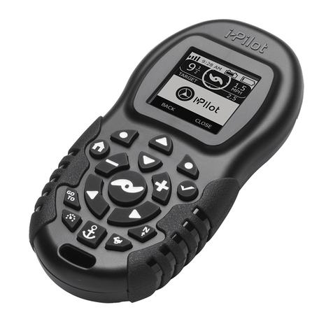
MINN KOTA MICRO REMOTE User manual

MICRO REMOTE
COMPACT WIRELESS REMOTE
OWNER'S MANUAL
COMPATIBLE WITH BLUETOOTH® ENABLED i-PILOT LINK OR i-PILOT SYSTEMS MANUFACTURED 2017 OR AFTER.

2 |
SAFETY CONSIDERATIONS
This remote will only work with Bluetooth® enabled i-Pilot
Link or i-Pilot systems. It is NOT compatible with systems that
do not use Bluetooth®. Refer to the remote images to ensure
system compatibility.
A Micro Remote for non-Bluetooth i-Pilot and Link systems is
also available (item #1866360).
Compatible with
Bluetooth®enabled
systems.
Not compatible with
non-Bluetooth
enabled systems.
Please thoroughly read the user manual. Follow all instructions and heed all safety and cautionary notices. Use of this product is
only permitted for persons that have read and understood these user instructions. Minors may use this product only under adult
supervision.
WARNING
This product contains chemical(s) known to the state of California to cause cancer and/or reproductive toxicity.
WARNING
You are responsible for the safe and prudent operation of your vessel. We have designed your Minn Kota product to be an
accurate and reliable tool that will enhance boat operation and improve your ability to catch fish. This product does not relieve
you from the responsibility for safe operation of your boat. You must avoid hazards to navigation and always maintain a
permanent watch so you can respond to situations as they develop. You must always be prepared to regain manual control of
your boat. Learn to operate your Minn Kota product in an area free from hazards and obstacles.
WARNING
It is recommended to only use Johnson Outdoors approved accessories with your motor, such as this i-Pilot Micro Remote.
Using non-approved accessories including to mount or control your motor may cause damage, unexpected motor operation
and injury. Be sure to use the product and approved accessories, including remotes, safely and in the manner directed to avoid
accidental or unexpected motor operation. Keep all factory installed parts in place including motor and accessory covers,
enclosures and guards.
WARNING
When the motor is being controlled by the i-Pilot navigation system, the Controller will continue to perform the last task it was
assigned, even when the remote is not powered on. Be sure to know how to power the motor "on" and "off", and always be alert
for unexpected motor movement, such as a turning propeller, even when the remote is powered "off". Refer to the Owner's
Manual for how to control the motor without the i-Pilot remote and become familiar with it's features including how to turn it
"on" and "off".
COMPATIBLE WITH BLUETOOTH® ENABLED i-PILOT LINK OR i-PILOT
SYSTEMS ONLY.

| 3
FEATURES
NOTE: Specifications subject to change without notice. This diagram is for reference only and may differ from your
actual motor.
Prop On/Off Increase Speed
Decrease Speed
Steer Right
Steer Left
High Speed Bypass AutoPilot
Spot-Lock
Spot-Lock
Press to enable Spot-Lock. When Spot-Lock is enabled from the Micro Remote, use either the i-Pilot or i-Pilot Link
remote, or the fish finder if you want to save it.
AutoPilot
Press to enable AutoPilot. The selection between Legacy AutoPilot and Advanced AutoPilot must be made from either
the i-Pilot or i-Pilot Link remote.
Speed Down & Speed Up
Press to decrease or increase motor speed.
Prop On/Off
Pressing this button will turn the Prop on and off.
Steer Left & Steer Right
Press to steer the motor to the left or to the right.
High Speed Bypass
Bypasses the current motor speed to speed 10.
Double press to engage. Single press to disengage.
NOTE: If your motor is connected to a Heading
Sensor, the Speed Down (backwards), Speed Up
(forward), Steer Right and Steer Left buttons
function change to Jog the boat while in Spot-Lock.
NOTE: The remote is waterproof.
MANUAL CONTROL BUTTONS
NAVIGATION BUTTONS

4 |
PAIRING THE MICRO REMOTE TO YOUR CONTROLLER
PAIRING THE MICRO REMOTE TO YOUR CONTROLLER
a. Power up the trolling motor.
b. Locate the Pair Button at the top of the Control
Head.
c. Push and hold the Pair Button down. A
consistent tone will be emitted from the
Control Head.
1
2d. While holding the Pair Button on the Control
Head, push and hold the High Speed Bypass and
AutoPilot keys on the remote simultaneously.
NOTE: When the remote is being paired
to the i-Pilot Controller, the High Speed
Bypass and the AutoPilot buttons need
to be held down simultaneously. Make
sure to also hold the Pair Button on the Control
Head to successfully pair the remote to the
controller.
NOTE: A remote can be paired to one
controller at a time. A controller can have
multiple remotes paired to it.
PAIR
Control Head - Ulterra & Riptide Ulterra
Control Head - Ultrex,
PowerDrive, Riptide
PowerDrive, Terrova &
Riptide Terrova
Pair Button
High Speed Bypass AutoPilot
e. Once successfully paired, 3 longer beeps will be
emitted from the Control Head and the remote will
be paired.
An i-Pilot controller may pair up to 5 remotes. These five remotes can be a combination of standard i-Pilot remotes and Micro
Remotes. Any additional remotes can be paired using the following steps. Once the maximum number of remotes have been
paired, the controller will start replacing the oldest paired remote in memory with the new remote.
NOTE: Make sure the remote stays within
range of the Control Head during the pairing
process.
PAIR

| 5
SERVICE & MAINTENANCE
AutoPilot
a. Make sure your hands are clean, dry and static
free. Temporarily ground yourself by touching a
grounded metal object in order to discharge any
static electricity in your body.
1Remote
Back
Battery
Cover
Unlock Icon
Arrow
Unlock Icon
Arrow
UTION
Static electricity can cause damage to the circuit board.
Discharge any static electricity by touching a metal object
that is grounded before beginning the remote battery
replacement.
b. With the remote upside down, use a large coin to
rotate the Battery Cover counterclockwise until
either of the Unlock Icons align with the Arrow.
2b
2
NOTE: The replacement battery must be a model
CR2450 coin cell type. It is strongly recommended
that a high quality battery is used.
c. Remove the Battery Cover and old battery and
replace with a new CR2450 coin cell battery.
Note the proper polarity of the battery.
Remote
Back Battery
Cover
Battery
REPLACING THE BATTERY
TOOLS AND RESOURCES REQUIRED
• Large Coin
INSTALLATION

6 |
SERVICE & MAINTENANCE
3d. Ensure the rubber O-ring is properly seated in
the underside of the Battery Cover. Replace
battery cover by aligning either of the Unlock
icons with the arrow, and pressing the cover
down.
e. Rotate the Battery Cover clockwise using the
large coin until the Lock Icon aligns with the
Arrow.
Remote
Back
Battery
Cover
Lock Icon
Arrow
Lock Icon
Arrow
Remote
Back
O-ring
Battery
Cover
Battery
3d
3e

| 7
COMPLIANCE STATEMENTS
ENVIRONMENTAL COMPLIANCE STATEMENT
It is the intention of JOME to be a responsible corporate citizen, operating in compliance with known and applicable
environmental regulations, and a good neighbor in the communities where we make or sell our products.
WEEE DIRECTIVE
EU Directive 2002/96/EC “Waste of Electrical and Electronic Equipment Directive (WEEE)” impacts most distributors, sellers,
and manufacturers of consumer electronics in the European Union. The WEEE Directive requires the producer of consumer
electronics to take responsibility for the management of waste from their products to achieve environmentally responsible
disposal during the product life cycle.
WEEE compliance may not be required in your location for electrical & electronic equipment (EEE), nor may it be required for
EEE designed and intended as fixed or temporary installation in transportation vehicles such as automobiles, aircraft, and boats.
In some European Union member states, these vehicles are considered outside of the scope of the Directive, and EEE for those
applications can be considered excluded from the WEEE Directive requirement.
This symbol (WEEE wheelie bin) on product indicates the product must not be disposed of with other household
refuse. It must be disposed of and collected for recycling and recovery of waste EEE. Johnson Outdoors Inc.
will mark all EEE products in accordance with the WEEE Directive. It is our goal to comply in the collection,
treatment, recovery, and environmentally sound disposal of those products; however, these requirements do
vary within European Union member states. For more information about where you should dispose of your waste
equipment for recycling and recovery and/or your European Union member state requirements, please contact
your dealer or distributor from which your product was purchased.
DISPOSAL
Minn Kota motors are not subject to the disposal regulations EAG-VO (electric devices directive) that implements the WEEE
directive. Nevertheless never dispose of your Minn Kota motor in a garbage bin but at the proper place of collection of your local
town council.
Never dispose of battery in a garbage bin. Comply with the disposal directions of the manufacturer or his representative and
dispose of them at the proper place of collection of your local town council.
WARNING
This product contains chemicals known to the State of California to cause cancer and birth defects or other reproductive harm.
REGULATORY COMPLIANCE INFORMATION
MICRO REMOTE
• Contains IC: 5123A-BGTBLE121LR
• Contains FCC ID: Q0QBLE121LR

8 |
COPLIANCE STATEMENTS
CE MASTER USER MANUAL (FOR CE CERTIFIED MODELS)
FCC COMPLIANCE
This device complies with Part 15 of the FCC rules.
Operation is subject to the following two conditions:
1. This device may not cause harmful interference.
2. This device must accept any interference that may be received, including interference that may cause undesired operation.
Changes or modifications not expressly approved by Johnson Outdoors Marine Electronics, Inc. could void the user’s authority to
operate this equipment.
INDUSTRY CANADA COMPLIANCE
This product meets the applicable Industry Canada technical specifications. Operation is subject to the following two conditions:
(1) this device may not cause interference, and (2) this device must accept any interference, including interference that may
cause undesired operation of the device.
Changes or modifications not expressly approved by Johnson Outdoors Marine Electronics, Inc. could void the user’s authority to
operate this equipment.
NOTE: This equipment has been tested and found to comply with the limits for a Class B digital device, pursuant to
part 15 of the FCC Rules. These limits are designed to provide reasonable protection against harmful interference in
a residential installation. This equipment generates, uses and can radiate radio frequency energy and, if not installed
and used in accordance with the instructions, may cause harmful interference to radio communications. However, there
is no guarantee that interference will not occur in a particular installation. If this equipment does cause harmful
interference to radio or television reception, which can be determined by turning the equipment off and
on, the user is encouraged to try to correct the interference by one or more of the following measures:
• Reorient or relocate the receiving antenna.
• Increase the separation between the equipment and receiver.
• Connect the equipment into an outlet on a circuit different from that to which the receiver is connected.
• Consult the dealer or an experienced radio/TV technician for help.
The Bluetooth® word mark and logos are registered trademarks owned by Bluetooth SIG, Inc. and any use of such marks by
Johnson Outdoors Inc is under license. Other trademarks and trade names are those of their respective owners.
TRADEMARKS

| 9
PARTS DIAGRAM & PARTS LIST
MICRO REMOTE
Assembly Part # Description Quantity
A2994079 RMT ASY, MICRO BLUETOOTH 1
B2886422 COVER, BATTERY COMPARTMENT ASY 1
Item Part # Description Quantity
22390800 LANYARD w/CARABINEER,IP REMOTE 1
4 p2394901 INSTR. SHEET,iPLT MICRO BT 1
6✖BATTERY CR2450 1
82372570 CASE-TOP, iPILOT MICRO REMOTE 1
10 2392550 CASE-BTTM, MICRO BLUETOOTH 1
12 ✖PAD-FOAM, I-PILOT 1.5 1
14 2375135 KEYPAD,iPILOT MICRO REMOTE 1
16 ✖COVER, BATTERY COMPRT 1
18 2376941 GASKET,BATTERY COMPARTMENT 1
20 ✖PCB ASSY, MICRO BLUETOOTH 1
Parts Diagram
Parts List
✖This part is included in an assembly and cannot be ordered individually.
pNot shown on Parts Diagram.
8
14
20
10
6
18
12
16
A
B
2
The parts diagram and parts list provides Minn Kota® WEEE compliance disassembly instructions. For more information about
where you should dispose of your waste equipment for recycling and recovery and/or your European Union member state
requirements, please contact your dealer or distributor from which your product was purchased. Tools required, but not limited
to: flat head screwdriver.

• 60-Amp Circuit Breaker
• Mounting Brackets
• Stabilizer Kits
• Extension Handles
• Battery Connectors
• Battery Boxes
• Quick Connect Plugs
RECOMMENDED ACCESSORIES
ON-BOARD & PORTABLE BATTERY CHARGERS
Stop buying new batteries and start taking care of the ones you’ve got. Many chargers can actually damage your
battery over time – creating shorter run times and shorter overall life. Digitally controlled Minn Kota chargers are designed to
provide the fastest charge that protect and extend battery life.
TALON SHALLOW WATER ANCHOR
Talon deploys faster, holds stronger and runs quieter than any other shallow water anchor. Available in depths up to 12’ and
bold color options including camo, it boasts an arsenal of features and innovations that no other anchor can touch:
MINN KOTA ACCESSORIES
We offer a wide variety of trolling motor accessories, including:
MK210D MK110P
• Vertical, Multi-Stage Deployment
• User-Selectable Anchoring Modes
• 2x Anchoring Force
• Fast Deploy
• Auto Up/Down
• Triple Debris Shields
• Built-In Wave Absorption
• Noise Dissipation
• Versatile Adjustments
MK212PC
Other manuals for MICRO REMOTE
2
Table of contents
Other MINN KOTA Remote Control manuals
MINN KOTA
MINN KOTA i-Pilot User manual
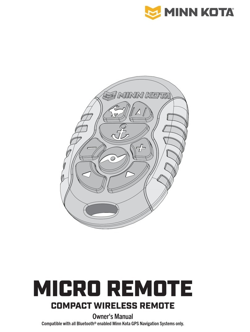
MINN KOTA
MINN KOTA MICRO REMOTE User manual
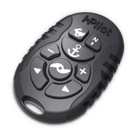
MINN KOTA
MINN KOTA MICRO REMOTE User manual

MINN KOTA
MINN KOTA i-Pilot User manual
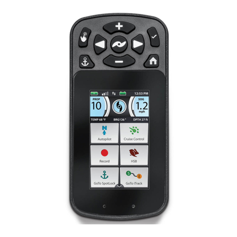
MINN KOTA
MINN KOTA i-Pilot Link User manual
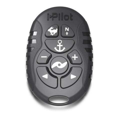
MINN KOTA
MINN KOTA i-PILOT MICRO REMOTE User manual

MINN KOTA
MINN KOTA i-Pilot User manual

MINN KOTA
MINN KOTA i-Pilot Link User manual
Popular Remote Control manuals by other brands
INVENTOR
INVENTOR RG35A/BGE owner's manual
Hunter
Hunter 41316-01 Owner's guide and installation manual
Daktronics
Daktronics RC-200 Operation manual

RADEMACHER
RADEMACHER Rollotron Pro Comfort Installation and operation manual

THOMSON
THOMSON 00131850 operating instructions
Link electronics
Link electronics PSR-826 Specification sheet
