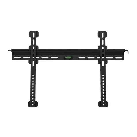
MINN KOTA MKA-51 User manual

1 | minnkotamotors.com ©2022 Johnson Outdoors Marine Electronics, Inc.
MKA-51 ELECTRIC-STEER
QUICK RELEASE BRACKET
1854051
TOOLS AND RESOURCES REQUIRED
Item /
Assembly Part # Description Qty.
A (Items 2-10) 2994936 BAG ASM, ES SLIDING QRB 1
2 2223446 SCREW-1/4-20 X 2" PFH SS 6
4 2373484 SCREW-1/4-20 X 7/8 PFH SS 6
6 2263103 NUT-1/4-20 NYLOCK SS 12
8 2261713 WASHER-1/4 FLAT 18-8 SS 6
10 2371712 WASHER-FLAT 9/32 X 5/8 X 1/16 6
B (Items 12-16) 2771998 BOTTOM PLATE KIT, MKA-51 QRB 1
12 2381958 PLATE-BOTTOM, QRB, MACH 1
14 2228413 CAM PUCK, MACHINED, ES QRB 1
16 2373428 SCREW-5/16-18 X 3/4" PFH SS 1
C (Items 18-40) 2771997 TOP PLATE KIT, MKA-51 QRB 1
18 2381956 PLATE-TOP, QRB, MACH 1
20 2373611 DRAWBAR, ES QRB 1
22 2222716 SPRING,COMPRESSION OD.480 1
24 2373260 STOP, DRAW BAR 1
26 2383431 SCREW-#12 X 5/8 TYPE B PFH SS 2
28 2225110 PAD, URETHANE,QCK ATTACH 1
30 2381948 EXTRUSION BACKER, MACH, ES QRB 1
32 2228415 CAM ARM, QCK ATTACH PLATE 1
34 2262635 PIN-ROLLER, S/S 1
36 2372623 PIN W/RING, QRB 1
38 2373650 LANYARD ELECTRIC STEER,QRB 1
40 2372644 PIN-ROLL, .093 x 5/8" SS 1
p2377169 MANUAL, ELEC.STEER SLIDING QRB 1
p2225615 DECAL-WARNING,MNT PLATE 1
40403030
2828
2222
3838
1818
2626
1414
1616
1212
3232
3434
3636
2424
2020
22
66
1010 8844
• #3 Phillips Screwdriver
• Drill
• 9/32” Drill Bit
• Awl or similar marking tool
• 7/16” Box End or
Open End Wrench
• A second person to help
with the installation
CC
BB
AA
Compatible with Minn Kota® Freshwater Electric-Steer Trolling Motor models, including the Ulterra™, Terrova®, PowerDrive™, PowerDrive V2 and DeckHand 40.
MOUNTING CONSIDERATIONS
It is recommended that the motor be mounted as close to the
centerline or keel of the boat as possible. The motor must not
encounter any obstructions as it is lowered into the water or raised
into the boat when stowed and deployed. Make sure the motor rest
is positioned far enough beyond the edge of the boat. Make sure the
area under the mounting location is flat, clear to drill holes and install
nuts and washers.
pNot shown on parts diagram.
NOTICE: The mounting surface for the Bottom Plate must
be completely flat. Rubber Washers can be used to shim
the Bottom Plate flat before hardware is tightened. The
Top Plate will not fit correctly unless the Bottom Plate is
installed completely flat.

2 | minnkotamotors.com ©2022 Johnson Outdoors Marine Electronics, Inc.
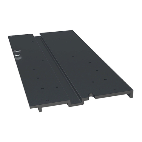
The MKA-51 Quick Release Bracket is designed to work on a number of Minn Kota trolling motors. The base extrusion or mounting
bracket of the trolling motors may vary. Please note the appearance of the applicable trolling motors and mounting bracket. For a
complete list of motors compatible with the MKA-51, please refer to the website minnkotamotors.com.
PowerDrive,PowerDrive,
PowerDrive V2PowerDrive V2
InboardInboard
UlterraUlterra
InboardInboard
TerrovaTerrova
InboardInboard
DeckHand 40DeckHand 40
InboardInboard
The MKA-51 Quick Release Bracket is designed to be locked in
two different positions. The first position aligns the Top Plate and
Bottom Plate and locks them in place with the Cam Lever. This
position is used when the motor is operating. The second position
allows the Top Plate to slide inboard 6 inches before it is locked
in place. This position is used during transporting. To slide the
bracket, open the Cam Lever and slide the Top Plate approximately
1½ inches sideways or Port side. Then slide the Top Plate 6 inches
inboard. Slide the Top Plate sideways again to close the 1½ inch
gap and realign the Plates. Close the Cam Lever and insert the Pin
to lock the Plates together. The Top Plate can be separated from
the Bottom Plate when slid into either of the two positions while a
sideways gap is present between the plates.
CompleteComplete
TypicalTypical
InstallationInstallation
CompleteComplete
TypicalTypical
InstallationInstallation
Operating Transporting
When checking clearances, make sure to check for obstructions
for the plate and motor when they are in all possible positions. The
plate moves sideways approximately 1½" and also slides inboard
6". This allows the motor to be moved for trailering, transport or a
boat cover without being removed. With this movement, make sure
to check for additional obstructions such as a windshield or lights.
The mounting location of the Quick Release Bracket will vary
depending on the motor that will be mounted:
1. For PowerDrive or Terrova motors: Fully deploy the motor and
position the mount on the bow of the boat to check for proper
clearance. The motor must not encounter any obstructions as it is lowered into the water or raised into the boat. When the motor is
deployed, there must be a minimum required distance of 1½" between the Gunwale and the Shaft.
2. For Ulterra Motors: Position the mount so the Slot in the Base Extrusion is positioned beyond the gunwale of the boat. For proper
clearance, the entire Slot must be visible beyond the gunwale. When the motor is deployed, there must be a minimum required distance
of 1½" between the Gunwale and the Shaft. The Ulterra motor cannot be deployed before mounting and connecting to a power source.
3. For the DeckHand 40: Mount the bracket using only the four holes that are farthest outboard. The two holes closest inboard are not
used to install the bracket. The Davit must always be mounted so it overhangs the bow by approximately nine inches. This leaves room
for the anchor to clear the boat and properly pivot in the Davit. For more information, refer to the DeckHand 40 owner's manual online
at minnkotamotors.com.
Ulterra
1-1/2"1-1/2"
MinimumMinimum
GunwaleGunwale
ShaftShaft
PowerDrive or Terrova
SlotSlot
GunwaleGunwale
NOTICE: Images are a graphical representation and may
vary slightly from your motor.

3 | minnkotamotors.com ©2022 Johnson Outdoors Marine Electronics, Inc.
INSTALLATION
#B x 1
a. Take the MKA-51 Quick Release Bracket, which
consists of the Top Plate (Assembly #C) and the
Bottom Plate (Assembly #B). Note the Cam Lever
attached to the Top Plate. The Plates are held
together when the Cam Lever is locked and secured
with the Pin. Remove the Pin from the Cam Lever to
release the Lever.
b. Open the Cam Lever by pulling it away from the
Quick Release Bracket.
NOTICE: The Cam Lever will only open and close in
one direction.
Top PlateTop Plate
PinPin
Cam LeverCam Lever
Bottom PlateBottom Plate
1ITEM(S) NEEDED
#C x 1
Opening the Bracket
a. Place the mount on an elevated, level surface such
as a workbench or the tailgate of a pickup. The
motor should be in the stowed position.
Power CablesPower Cables
DeployedDeployed StowedStowed
NOTICE: A motor may weigh up to 65lbs. Minn Kota
recommends having a second person help with
the installation.
1
Installing the Top Plate to a Terrova, PowerDrive or PowerDrive V2
NOTICE: The Top Plate can be separated from the
Bottom Plate when a sideways gap is present between
the Plates.
c. When the Top Plate is attached to the Base
Extrusion, the end of the Top Plate with the Cam
Lever will mount inboard.
d. With the Cam Lever open, Slide the Top Plate
portside 1½", then lift to separate it from the Bottom
Plate. Set the Bottom Plate aside. The Top Plate will
be installed first.
InboardInboard
StarboardStarboard
PortPort
OutboardOutboard
Cam LeverCam Lever
Slide 1½" PortsideSlide 1½" Portside
WARNING
Make sure that the Power Cables from the battery are
disconnected or that the breaker, if equipped, is “off.”
BowBow
Top PlateTop Plate

4 | minnkotamotors.com ©2022 Johnson Outdoors Marine Electronics, Inc.
Right SideplateRight Sideplate
Mounting HolesMounting Holes
Base ExtrusionBase Extrusion
b. Remove the four Sideplate screws using a #3 Phillips
Screwdriver. Two Screws will be located on each side
of the mount.
c. Remove the Right Sideplate.
d. Swing the Left Sideplate out and away from the Base
Extrusion. Removing the sideplates exposes the
mounting holes in the Base Extrusion.
Sideplate ScrewsSideplate Screws
2
2c
2b
2d
Left SideplateLeft Sideplate

5 | minnkotamotors.com ©2022 Johnson Outdoors Marine Electronics, Inc.
e. Place the flat side of the Top Plate (Assembly #C)
against the bottom of the Base Extrusion. Align the
Mounting Holes in the Top Plate with the Mounting
Holes in the Base Extrusion that were exposed when
the sideplates were removed. Make sure that the
Cam Lever points inboard. The appearance of the
Base Extrusion may vary depending on motor type.
#4 x 6 #10 x 6 #6 x 6
NOTICE: To prevent seizing of the stainless steel
hardware, do not use high speed installation tools.
Wetting the screws or applying an anti-seize may help
prevent seizing.
Top PlateTop Plate
Cam LeverCam Lever
MountingMounting
HolesHoles
MountingMounting
HolesHoles
Base ExtrusionBase Extrusion
StainlessStainless
Steel ScrewSteel Screw
Nylock NutsNylock Nuts
Flat WasherFlat Washer
OutboardOutboard
InboardInboard
g. With the Top Plate secured to the Base Extrusion,
replace the Right Sideplate.
h. Swing the Left Sideplate back into its correct
position on the Base Extrusion.
i. Replace the four sideplate screws using a #3 Phillips
Screwdriver. Two of these screws will be used on
each side of the mount.
Right SideplateRight Sideplate
Left SideplateLeft Sideplate
Base ExtrusionBase Extrusion
3
4
4g
4h
ITEM(S) NEEDED
Sideplate ScrewSideplate Screw
4i
f. Use six each of the Stainless Steel Screws (Item #4),
Flat Washers (Item #10) and Nylock Nuts (Item #6)
to secure the Top Plate to the Base Extrusion. The
Screws should pass from the bottom up, through the
Top Plate and into the Base Extrusion. Place a Flat
Washer on each Screw on top of the Base Extrusion,
and then secure with the Nylock Nuts. Tighten the
Nylock Nuts with a 7/16” Box End or Open End
Wrench. Make sure all hardware is secure.
#C x 1

6 | minnkotamotors.com ©2022 Johnson Outdoors Marine Electronics, Inc.
1
Installing the Top Plate to a DeckHand 40
a. Remove the DeckHand 40 cover. Place the Davit
just inside the Base so that the two mounting holes
on the edge of the Davit align with the two mounting
holes on the edge of the Base. The Davit should
point outboard.
b. Position the combined Base and Davit over the
Top Plate (Assembly #C). The Cam Lever on the
Top Plate should point inboard. Align the mounting
holes in the Top Plate with the mounting holes in the
Base and Davit. Only the four holes that are farthest
outboard will be used to install the Top Plate to the
Deckhand 40. The remaining two holes furthest
inboard will not be used.
c. Take four each of the Stainless Steel Screws
(Item #4), Flat Washers (Item #10) and Nylock Nuts
(Item #6). Insert the Screws from the bottom up,
through the Top Plate and into the DeckHand 40
Base and Davit. Place a Flat Washer and Nylock Nut
on the end of each Screw. Tighten the Nylock Nuts
with a 7/16" Box End or Open End Wrench. Make
sure all hardware is secure. Reattach the cover of
the DeckHand 40.
ITEM(S) NEEDED
#C x 1
InboardInboard
InboardInboard
Top PlateTop Plate
Top PlateTop Plate
MountingMounting
HolesHoles
DeckHand 40DeckHand 40
Base and DavitBase and Davit
#4 x 4 #10 x 4 #6 x 4
1c
1b
OutboardOutboard
OutboardOutboard
Nylock NutNylock Nut
Flat WasherFlat Washer
StainlessStainless
Steel ScrewSteel Screw
InboardInboard
DavitDavit
Mounting HolesMounting Holes
BaseBase OutboardOutboard
1a
NOTICE: For more detailed instructions on installing a
DeckHand 40, refer to the DeckHand 40 owner's
manual online at minnkotamotors.com.
NOTICE: To prevent seizing of the stainless steel
hardware, do not use high-speed installation tools.
Wetting the screws or applying an anti-seize may help
prevent seizing.
CamCam
LeverLever

7 | minnkotamotors.com ©2022 Johnson Outdoors Marine Electronics, Inc.
Installing the Top Plate to an Ulterra
Power CablesPower Cables
1
DeployedDeployed
StowedStowed
a. Place the mount on an elevated, level surface such
as a workbench or the tailgate of a pickup. The
motor should be in the stowed position.
NOTICE: This installation requires the use of hardware
that was included with the Ulterra motor. Six Clipped
Washers (Part #2201725) from the Ulterra Bag
Assembly (Part #2994917) will be needed.
NOTICE: A motor may weigh up to 65lbs. Minn Kota
recommends having a second person help with
the installation.
WARNING
Make sure that the Power Cables from the battery are
disconnected or that the breaker, if equipped, is “off.”
b. With a #3 Screwdriver, remove the four Sideplate
Screws. Two of these screws will be located on each
side of the mount.
c. Remove the Right Sideplate to access the
Mounting Slots.
d. Remove the Left Sideplate to access the
Mounting Holes.
LeftLeft
SideplateSideplate
RightRight
SideplateSideplate
2c 2d
e. Under the Left Sideplate, the Extension Damper
obstructs access to the front-left Mounting Hole.
f. Using a small Screwdriver, remove the two 5/16"
E-clips holding the Extension Damper in place. Once
the E-clips are removed, slide the Extension Damper
off the Damper Pins to expose the left rear Mounting
Hole. Set the two E-clips and Extension Damper in
a safe place so they are not misplaced. They will be
reassembled later in the installation.
E-clipsE-clips ExtensionExtension
DamperDamper Damper PinsDamper Pins
ExtensionExtension
DamperDamper
E-clipE-clip
E-clipE-clip
Mounting HoleMounting Hole
3e
3f
3
2
WARNING
Illustrations are for reference only. Do not deploy the motor until
it is fully mounted to the boat. Deploying your motor before it is
mounted to the boat may cause injury.

8 | minnkotamotors.com ©2022 Johnson Outdoors Marine Electronics, Inc.
NOTICE: To prevent seizing of the stainless steel
hardware, do not use high-speed installation tools.
Wetting the screws or applying an anti-seize may
help prevent seizing.
ClippedClipped
WasherWasher
Power TiltPower Tilt
TopTop
PlatePlate
Cam LeverCam Lever
InboardInboard StainlessStainless
Steel ScrewSteel Screw
g. Start with the right side of the Ulterra, where the
Power Tilt is located. There are three Mounting Slots
in the Base Extrusion. These will be used to slide
the Ulterra onto the mounting hardware after it is
installed in the Top Plate (Assembly #C). Ensure that
the Cam Lever on the Top Plate points inboard.
h. Install the Top Plate to the Base Extrusion using
three Stainless Steel Screws (Item #4), three Clipped
Washers (Item #2201725), and three Nylock Nuts
(Item #6). Insert the Screws into the Top Plate from
the bottom up. Place a Clipped Washer on the end
of each Screw, leaving at least 1/4" space between
the Top Plate and Clipped Washer to allow the Base
Extrusion to slide under the Clipped Washers and
into place. Ensure that the flat side of the Washers
faces toward the Base Extrusion.
CAUTION
Use extra care to avoid pinching and damaging the sensor
wires that run alongside the Base Extrusion when installing and
tightening the mounting hardware.
4h
4
NOTICE: This installation will require six Clipped
Washers (Part #2201725) from the Ulterra Bag
Assembly (Part #2994917).
i. Slide the Base Extrusion into place on the Screws.
The Base Extrusion should slide between the Top
Plate and the Clipped Washers. Hold the Clipped
Washers up on the Screws so that the Clipped
Washers will sit on top of the Base Extrusion.
j. With the motor in place, secure each Screw with a
Nylock Nut. Tighten with a 7/16” Box End or Open
End Wrench. Make sure all hardware is secure. BaseBase
ExtrusionExtrusion
Top PlateTop Plate
ClippedClipped
WasherWasher
5i
5
ITEM(S) NEEDED
#C x 1 #4 x 6 #10 x 6 #6 x 6
Top PlateTop Plate
Nylock NutNylock Nut
5j

9 | minnkotamotors.com ©2022 Johnson Outdoors Marine Electronics, Inc.
k. Move to the other side of the Ulterra to install the
remaining hardware. Ensure that the Mounting Holes
in the Base Extrusion are aligned with the Mounting
Holes in the Top Plate.
l. Take three each of the Stainless Steel Screws,
Clipped Washers and Nylock Nuts. Insert the Screws
from the bottom up, through the Top Plate and into
the Base Extrusion. Place a Clipped Washer on each
Screw, positioned so that the flat side of the Washer
faces toward the Base Extrusion. Secure each Screw
with a Nylock Nut and tighten with a 7/16” Box End or
Open End Wrench. Make sure all hardware is secure.
Mounting HolesMounting Holes
MountingMounting
HoleHole
TopTop
PlatePlate
Stainless Steel ScrewStainless Steel Screw
ClippedClipped
WasherWasher
NylockNylock
NutNut
CAUTION
Use extra care to avoid pinching and damaging the
sensor wires that run alongside the Base Extrusion
when installing and tightening the mounting hardware.
66k
6l
m. At this point in the installation, the Motor should
be secured to the Top Plate and can now be
reassembled. Slide the Extension Damper back
in place on the Damper Pins. This should be done
so the shaft on the Damper is pointing inboard.
Reinstall the two 5/16” E-clips.
E-clipsE-clips ExtensionExtension
DamperDamper Damper PinsDamper Pins
7
n. Replace the Right Sideplate.
o. Replace the Left Sideplate.
p. Reinstall the four Sideplate Screws using a #3
Phillips Screwdriver.
Left SideplateLeft Sideplate ScrewScrew
ScrewScrew
ScrewScrew
Right SideplateRight Sideplate
ScrewScrew
88n
8o
InboardInboard

10 | minnkotamotors.com ©2022 Johnson Outdoors Marine Electronics, Inc.
a. With the Top Plate secured to the motor, reassemble
the Quick Release Bracket. To reassemble the
MKA-51, set the Top Plate and motor onto the
Bottom Plate (Assembly #B), leaving a 1½" sideways
gap between the Plates. Slide the Top Plate and
motor sideways to close the gap and realign the
Plates. Secure the Plates together by closing the
Cam Lever and inserting the Pin.
b. Place the motor with the MKA-51 attached as close
to the centerline or keel of the boat as possible. The
motor can be installed on either the Port or Starboard
side of the boat based on personal preference.
Review the Mounting Considerations at the beginning
of this document to ensure proper clearances.
Deck ofDeck of
BoatBoat
KeelKeel
NOTICE: Make sure that the motor will not encounter
any obstructions when sliding the motor on and off the
Quick Release Bracket. The exact placement of the
motor when mounting may vary depending on the boat,
boat deck, and base extrusion or bracket the MKA-51 is
being mounted to. The Ulterra motor cannot be deployed
before mounting and connecting a power source.
NOTICE: The mounting surface for the Bottom Plate
must be completely flat. Rubber Washers can be used to
shim the Bottom Plate flat before hardware is tightened.
The Top Plate will not fit correctly unless the Bottom
Plate is installed completely flat.
Bow ofBow of
BoatBoat
PossiblePossible
Position ofPosition of
Top PlateTop Plate
OutboardOutboard
InboardInboard
1
1b
1c
Installing the Bottom Plate to the Bow
OutboardOutboard
InboardInboard
StarboardStarboard
PortPort
1a
BottomBottom
PlatePlate
CamCam
LeverLever
TopTop
PlatePlate
c. When checking clearance, make sure to check for
obstructions around the MKA-51 and motor when
they are in all possible positions. The Top Plate
moves sideways approximately 1½" and also slides
inboard 6". This allows the motor to be moved for
trailering, transport, or a boat cover without being
removed. With this movement in mind, make sure
to check for additional obstructions, such as a
windshield or lights.
ITEM(S) NEEDED
#B x 1

11 | minnkotamotors.com ©2022 Johnson Outdoors Marine Electronics, Inc.
f. Reposition the Bottom Plate on the marks made on
the bow of the boat. Make sure the Padlock Slot is
facing inboard. Locate the six mounting holes in the
Bottom Plate and mark them on the bow. Set the
Bottom Plate aside.
g. Drill through the boat deck using a Drill and 9/32"
Drill Bit on the marked locations.
DrillingDrilling
LocationsLocations
BottomBottom
PlatePlate
InboardInboard
Padlock SlotPadlock Slot
OutboardOutboard
h. Reposition the Bottom Plate over the drilled holes.
Ensure that the Padlock Slot points inboard. Insert
a Flat Head Screw (Item #2) in each of the six drilled
locations. The Screws should be inserted from
the top down, through the Bottom Plate, Rubber
Washers (if used), and into the boat deck.
i. Place a Flat Washer (Item #8) and then a Nylock Nut
(Item #6) on the end of each Screw and tighten with
a 7/16” Box End or Open End Wrench. Make sure all
hardware is secure.
Flat HeadFlat Head
ScrewScrew
Bottom PlateBottom Plate
Flat WasherFlat Washer
Nylock NutNylock Nut
Padlock SlotPadlock Slot
BoatBoat
DeckDeck
NOTICE: The mounting surface for the Bottom Plate
must be completely flat. Rubber Washers can be used to
shim the Bottom Plate flat before hardware is tightened.
The Top Plate will not fit correctly unless the Bottom
Plate is installed completely flat.
NOTICE: To prevent seizing of the stainless steel hardware,
do not use high-speed installation tools. Wetting the screws
or applying an anti-seize may help prevent seizing.
#2 x 6 #8 x 6 #6 x 6
InboardInboard
OutboardOutboard
3
4ITEM(S) NEEDED
d. With an Awl or similar marking tool, mark the side and
rear edges of the Bottom Plate on the bow of the boat.
e. Remove the Pin and open the Cam Lever. Separate
the Top Plate and motor from the Bottom Plate.
Bow ofBow of
BoatBoat
Bow ofBow of
BoatBoat
BottomBottom
PlatePlate
MarkingsMarkings
Bottom PlateBottom Plate
MarkingsMarkings
PinPin BowBow MarkingsMarkings
Top PlateTop Plate
Cam LeverCam Lever
22d 2d
2e

a. Slide the Top Plate and motor onto the Bottom Plate
that was mounted to the Boat Deck. Secure with the
Cam Lever and Pin. Always check to be sure that
the Cam Lever is closed and secured with the Pin to
ensure that the Cam Lever remains latched.
NOTICE: Lock your motor
to help prevent theft.
The motor can be locked
in either the operating or
transporting position.
BottomBottom
PlatePlate
Top PlateTop Plate
PinPin
Cam LeverCam Lever
For warranty information, please visit minnkotamotors.com.
1
Minn Kota Consumer & Technical Service
Johnson Outdoors Marine Electronics, Inc.
PO Box 8129
Mankato, MN 56001
121 Power Drive
Mankato, MN 56001
Phone (800) 227-6433
Fax (800) 527-4464
minnkotamotors.com
©2022 Johnson Outdoors Marine Electronics, Inc.
All rights reserved.
Part #2377169 Rev D 12/22ECN 43066
Completing the Installation
OperatingOperating
TransportingTransporting
CAUTION
Before locking the Cam Lever, make sure that the rails of the
Top Plate and Bottom Plate seat into their respective channels.
Improper alignment will allow the motor to fall off, even if the
Cam Lever is locked.

13 | minnkotamotors.com ©2022 Johnson Outdoors Marine Electronics, Inc.
SUPPORT À DÉGAGEMENT RAPIDE À
COMMANDE ÉLECTRIQUE MKA-51
1854051
Article/
Ensemble Nº de
pièce Description Qté
A
Articles 2 à 10 2994936 BAG ASM, ES SLIDING QRB 1
2 2223446 SCREW-1/4-20 X 2" PFH SS 6
4 2373484 SCREW-1/4-20 X 7/8 PFH SS 6
6 2263103 NUT-1/4-20 NYLOCK SS 12
8 2261713 WASHER-1/4 FLAT 18-8 SS 6
10 2371712 WASHER-FLAT 9/32 X 5/8 X 1/16 6
B
Articles 12 à 16 2771998 BOTTOM PLATE KIT, MKA-51 QRB 1
12 2381958 PLATE-BOTTOM, QRB, MACH 1
14 2228413 CAM PUCK, MACHINED, ES QRB 1
16 2373428 SCREW-5/16-18 X 3/4" PFH SS 1
C
Articles 18 à 40 2771997 TOP PLATE KIT, MKA-51 QRB 1
18 2381956 PLATE-TOP, QRB, MACH 1
20 2373611 DRAWBAR, ES QRB 1
22 2222716 SPRING,COMPRESSION OD.480 1
24 2373260 STOP, DRAW BAR 1
26 2383431 SCREW-#12 X 5/8 TYPE B PFH SS 2
28 2225110 PAD, URETHANE,QCK ATTACH 1
30 2381948 EXTRUSION BACKER, MACH, ES QRB 1
32 2228415 CAM ARM, QCK ATTACH PLATE 1
34 2262635 PIN-ROLLER, S/S 1
36 2372623 PIN W/RING, QRB 1
38 2373650 LANYARD ELECTRIC STEER,QRB 1
40 2372644 PIN-ROLL, .093 x 5/8" SS 1
p2377169 MANUAL, ELEC.STEER SLIDING QRB 1
p2225615 DECAL-WARNING,MNT PLATE 1
40403030
2828
2222
3838
1818
2626
1414
1616
1212
3232
3434
3636
2424
2020
22
66
1010 8844
• Tournevis cruciforme nº 3
• Perceuse
• Mèche de 9/32 po (7,1 mm)
• Poinçon ou autre outil de
marquage semblable
• Clé polygonale ou ouverte
de 7/16 po (11,1 mm)
• Une deuxième personne
pour vous aider avec
l’installation
CC
BB
AA
Compatible avec les modèles de moteur de pêche à la traîne en eau douce à commande électrique Minn Kota®, y compris Ulterra™, Terrova®,
PowerDrive™, PowerDrive V2 et DeckHand 40.
pNon affiché sur le schéma des pièces.
OUTILS ET RESSOURCES NÉCESSAIRES

14 | minnkotamotors.com ©2022 Johnson Outdoors Marine Electronics, Inc.
Le support à dégagement rapide MKA-51 est conçu pour fonctionner sur plusieurs moteurs de pêche à la traîne Minn Kota. L’extrusion
de la base ou le support de montage des moteurs de pêche à la traîne peut varier. Veuillez noter l’apparence des moteurs de pêche à la
traîne et des supports de montage concernés. Pour une liste complète des moteurs compatibles avec le MKA-51, veuillez consulter le
site Web minnkotamotors.com.
PowerDrive,PowerDrive,
PowerDrive V2PowerDrive V2
En-bordEn-bord
UlterraUlterra
En-bordEn-bord
TerrovaTerrova
En-bordEn-bord
DeckHand 40DeckHand 40
En-bordEn-bord
Le support à dégagement rapide MKA-51 est conçu pour être
verrouillé en deux positions différentes. La première position enligne
la plaque supérieure et la plaque inférieure qui les verrouille en
place avec le levier à came. Cette position est utilisée lorsque le
moteur est en marche. La deuxième position permet de glisser de 6
po (15 cm) la plaque supérieure vers l’en-bord avant de la verrouiller
en place. Cette position est utilisée pendant le transport. Pour
faire glisser le support, ouvrez le levier à came et faites glisser la
plaque supérieure d’environ 1 1/2 po (3,81 cm) latéralement ou côté
bâbord. Ensuite, glissez la plaque supérieure de 6 po (15 cm) vers
l’intérieur. Glissez à nouveau la plaque supérieure latéralement pour
combler l’espace de 1 1/2 po (3,81 cm) et réenligner les plaques.
Fermez le levier à came et insérez la goupille pour verrouiller les
plaques ensemble. La plaque supérieure peut être séparée de la
plaque inférieure lorsqu’elle est glissée dans l’une ou l’autre des deux positions lorsqu’il existe un écart latéral entre les plaques.
InstallationInstallation
complètecomplète
typiquetypique
InstallationInstallation
complètecomplète
typiquetypique
En fonctionnement En transport
Lors de la vérification des dégagements, assurez-vous de vérifier s’il y a des obstructions à la plaque et au moteur lorsqu’ils sont dans toutes
les positions possibles. La plaque se déplace vers le côté d’environ 1 1/2 po (3,81 cm) et se glisse aussi vers l’en-bord de 6 po (15 cm). Cela
permet de déplacer le moteur pour le remorquer, le transporter ou de couvrir le bateau, sans être retiré. Assurez-vous de vérifier s’il y a
d’autres obstructions avec ce mouvement, comme un pare-brise ou des phares.
L’emplacement de montage du support à dégagement rapide variera selon le moteur qui sera monté :
1. Pour les moteurs PowerDrive ou Terrova : Déployez pleinement le moteur et positionnez la fixation sur l’étrave du bateau afin de vérifier
que le dégagement est approprié. Le moteur ne doit rencontrer aucune obstruction lorsqu’il est abaissé dans l’eau ou monté dans le
bateau. Lorsque le moteur est déployé, il doit y avoir une distance minimale requise de 1½ po (3,81 cm) entre le plat-bord et l’arbre.
AVIS : Les images sont une représentation graphique et
peuvent être légèrement différentes de votre moteur.
Il est recommandé que le moteur soit monté aussi près que possible
de l’axe ou de la quille du bateau. Le moteur ne doit rencontrer
aucune obstruction lorsqu’il est abaissé dans l’eau ou monté dans le
bateau pour arrimage ou déploiement. Assurez-vous que le repose-
moteur est positionné assez loin du bord du bateau. Vérifiez que
la zone sous l’emplacement de montage est dégagée et plate pour
percer des trous et installer des rondelles et des écrous.
AVIS : La surface de montage pour la plaque inférieure doit être
complètement à plat. Des rondelles en caoutchouc peuvent être
utilisées pour caler la plaque inférieure afin qu’elle soit à plat avant
le serrage de la quincaillerie. La plaque supérieure ne s’ajustera
pas correctement si la plaque inférieure n’est pas installée
complètement à plat.
FACTEURS DE MONTAGE

15 | minnkotamotors.com ©2022 Johnson Outdoors Marine Electronics, Inc.
INSTALLATION
#B x 1
a. Prenez le support à dégagement rapide MKA-51, qui
comprend la plaque supérieure (assemblage nº C) et
la plaque inférieure (assemblage nº B). Remarquez le
levier à came fixé à la plaque supérieure. Les plaques
sont maintenues ensemble lorsque le levier à came
est verrouillé et fixé avec une goupille. Retirez la
goupille du levier à came pour libérer le levier.
b. Ouvrez le levier à came en le tirant hors du support à
dégagement rapide.
AVIS : Le levier à came ne s’ouvre et ne se ferme que
dans une seule direction.
PlaquePlaque
supérieuresupérieure
GoupilleGoupille
Levier à cameLevier à came
Plaque inférieurePlaque inférieure
1ARTICLE(S) REQUIS
#C x 1
Ouverture du support
AVIS : La plaque supérieure peut être séparée de la
plaque inférieure lorsqu’elle lorsqu’il existe un écart
latéral entre les plaques.
c. Lorsque la plaque supérieure est fixée à l’extrusion
de la base, l’extrémité de la plaque supérieure avec
le levier à came se monte à l’en-bord.
d. Le levier à came ouvert, faites glisser la plaque
supérieure côté bâbord de 1½ po (3,81 cm), puis
soulevez-la pour la séparer de la plaque inférieure.
Mettez la plaque inférieure de côté. La plaque
supérieure sera installée en premier.
En-bordEn-bord
TribordTribord
BâbordBâbord
Hors-bordHors-bord
Levier à cameLevier à came
Glisser 1½ po (3,81 cm)Glisser 1½ po (3,81 cm)
côté bâbordcôté bâbord
ProueProue
Plaque supérieurePlaque supérieure
2. Pour les moteurs Ulterra : Orientez le support de manière à ce
que la fente de l’extrusion de la base soit positionnée au-delà
du plat-bord du bateau. Le dégagement est approprié lorsque
la totalité de la fente est visible au-delà du plat-bord. Lorsque
le moteur est déployé, il doit y avoir une distance minimale
requise de 1½ po (3,81 cm) entre le plat-bord et l’arbre. Le
moteur Ulterra ne peut pas être déployé avant le montage et la
connexion à une source d’alimentation.
3. Pour le DeckHand 40 : Le bossoir doit toujours être monté
de manière à dépasser l’étrave d’environ neuf pouces
(22,8 cm). Cela laisse de la place pour que l’ancre puisse
dégager le bateau et pivoter correctement dans le bossoir. Pour en savoir plus, veuillez consulter le manuel du propriétaire du
DeckHand 40 en ligne à l’adresse minnkotamotors.com. Montez le support en utilisant seulement les quatre trous qui sont le plus loin
hors-bord. Les deux trous les plus proches en-bord ne sont pas utilisés pour installer le support.
Ulterra
Minimum de 1,5 poMinimum de 1,5 po
(3,8 cm)(3,8 cm)
Plat-bordPlat-bord ArbreArbre
PowerDrive ou Terrova
FenteFente
Plat-bordPlat-bord

16 | minnkotamotors.com ©2022 Johnson Outdoors Marine Electronics, Inc.
Plaque latérale droitePlaque latérale droite
Trous de montageTrous de montage
Extrusion de la baseExtrusion de la base
b. Retirez les quatre vis de la plaque latérale en
utilisant un tournevis cruciforme nº 3. Deux vis
seront situées de chaque côté du support.
c. Enlevez la plaque latérale droite.
d. Faites pivoter la plaque latérale gauche en
l’éloignant de l’extrusion de la base. Le retrait des
plaques latérales expose les trous de montage dans
l’extrusion de la base.
Vis de plaque latéraleVis de plaque latérale
2
2c
2b
2d
Plaque latéralePlaque latérale
gauchegauche
a. Placez le support sur une surface élevée, de niveau,
comme un établi ou le hayon d’une camionnette.
Le moteur devrait être en position arrimée.
Câbles d’alimentationCâbles d’alimentation
DéployéDéployé ArriméArrimé
AVIS : Un moteur peut peser jusqu’à 65 lb (29,5 kg).
Minn Kota recommande d’obtenir l’aide d’une deuxième
personne pour l’installation.
1
Installation de la plaque supérieure sur un modèle Terrova, PowerDrive ou PowerDrive V2
AVERTISSEMENT
Assurez-vous que les câbles d’alimentation de la
batterie sont déconnectés, ou que le disjoncteur, le
cas échéant, est en position « arrêt ».

17 | minnkotamotors.com ©2022 Johnson Outdoors Marine Electronics, Inc.
e. Placez le côté plat de la plaque supérieure
(ensemble nº C) contre le bas de l’extrusion de la
base. Enlignez les trous de montage dans la plaque
supérieure et les trous de montage dans l’extrusion
de la base qui ont été exposés lorsque les plaques
latérales ont été retirées. Assurez-vous que le
levier à came pointe vers l’intérieur. L’apparence
de l’extrusion de la base peut varier selon le type
de moteur.
f. À l’aide de six vis en acier inoxydable (article nº 4),
de la rondelle plate (article nº 10) et des écrous
Nylock (article nº 6), fixez la plaque supérieure à
l’extrusion de la base. Les vis doivent passer de
bas en haut, à travers la plaque supérieure et dans
l’extrusion de la base. Placez une rondelle plate sur
chaque vis au sommet de l’extrusion de la base, puis
fixez-les avec les écrous Nylock. Serrez les écrous
Nylock avec une clé polygonale ou une clé ouverte
de 7/16 po (11,1 mm). Assurez-vous que toute la
quincaillerie est bien fixée.
#4 x 6 #10 x 6 #6 x 6
AVIS : Pour prévenir le grippage de la quincaillerie en
acier inoxydable, n’utilisez pas d’outils haute vitesse pour
l’installation. Mouiller les vis ou appliquer un produit
antigrippant peut aider à prévenir qu’elles grippent.
PlaquePlaque
supérieuresupérieure
Levier à cameLevier à came
Trous deTrous de
montagemontage
Trous deTrous de
montagemontage
ExtrusionExtrusion
de la basede la base
Vis en acierVis en acier
inoxydableinoxydable
Écrou NylockÉcrou Nylock
Rondelle plateRondelle plate
Hors-bordHors-bord
En-bordEn-bord
g. Une fois la plaque supérieure fixée à l’extrusion de la
base, remplacez la plaque latérale droite.
h. En la faisant pivoter, replacez la plaque latérale
gauche dans sa position appropriée sur l’extrusion
de la base.
i. Replacez les quatre vis de la plaque latérale en
utilisant un tournevis cruciforme nº 3. Deux de ces
vis seront utilisées de chaque côté du support.
Plaque latérale droitePlaque latérale droite
Plaque latéralePlaque latérale
gauchegauche
Extrusion de la baseExtrusion de la base
3
4
4g
4h
ARTICLE(S) REQUIS
Vis de plaque latéraleVis de plaque latérale
4i
#C x 1

18 | minnkotamotors.com ©2022 Johnson Outdoors Marine Electronics, Inc.
1
Installation de la plaque supérieure sur un DeckHand 40
a. Retirez le couvercle du DeckHand 40. Placez le
bossoir juste à l’intérieur de la base de façon à ce
que les deux trous de montage sur le bord du bossoir
et les deux trous de montage sur le bord de la
base soient enlignés. Le bossoir doit être orienté
vers l’extérieur.
b. Placez la base et le bossoir combinés sur la plaque
supérieure (assemblage nº C). Le levier à came de la
plaque supérieure doit être orientée vers l’intérieur.
Enlignez les trous de montage de la plaque
supérieure et les trous de montage de la base et du
bossoir. Seuls les quatre trous les plus à l’extérieur
seront utilisés pour installer la plaque supérieure sur
le Deckhand 40. Les deux trous restants les plus à
l’intérieur ne seront pas utilisés.
c. Prenez quatre vis en acier inoxydable (article nº 4),
quatre rondelles plates (article nº 10) et quatre écrous
Nylock (article nº 6). Insérez les vis de bas en haut,
à travers la plaque supérieure et dans la base et le
bossoir du DeckHand 40. Placez une rondelle plate
et un écrou Nylock à l’extrémité de chaque vis. Serrez
les écrous Nylock avec une clé polygonale ou une clé
ouverte de 7/16 po (11,1 mm). Assurez-vous que toute
la quincaillerie est bien fixée. Remettez le couvercle
du DeckHand 40 en place.
ARTICLE(S) REQUIS
#C x 1
En-bordEn-bord
En-bordEn-bord
PlaquePlaque
supérieuresupérieure
Plaque supérieurePlaque supérieure
Trous deTrous de
montagemontage
Bossoir et baseBossoir et base
DeckHand 40DeckHand 40
#4 x 4 #10 x 4 #6 x 4
1c
1b
Hors-bordHors-bord
Hors-bordHors-bord
Écrou NylockÉcrou Nylock
Rondelle plateRondelle plate
Vis en acierVis en acier
inoxydableinoxydable
En-bordEn-bord
BossoirBossoir
Trous de montageTrous de montage
BaseBase Hors-bordHors-bord
1a
AVIS : Pour obtenir des instructions plus détaillées
sur l’installation d’un DeckHand 40, consultez le
manuel du propriétaire du DeckHand 40 en ligne sur
minnkotamotors.com.
AVIS : Pour prévenir le grippage de la quincaillerie en
acier inoxydable, n’utilisez pas d’outils haute vitesse pour
l’installation. Mouiller les vis ou appliquer un produit
antigrippant peut aider à prévenir qu’elles grippent.
LevierLevier
à cameà came
LevierLevier
à cameà came

19 | minnkotamotors.com ©2022 Johnson Outdoors Marine Electronics, Inc.
Installation de la plaque supérieure sur un Ulterra
Câbles d’alimentationCâbles d’alimentation
1
DéployéDéployé ArriméArrimé
a. Placez le support sur une surface élevée, de niveau,
comme un établi ou le hayon d’une camionnette.
Le moteur devrait être en position arrimée.
AVIS : Cette installation nécessite l’utilisation de la
quincaillerie qui était incluse avec le moteur Ulterra.
Six rondelles taillées (pièce n° 2201725) de
l’assemblage dans le sac de quincaillerie du moteur
Ulterra (nº 2994917) seront nécessaires.
AVIS : Un moteur peut peser jusqu’à 65 lb (29,5 kg).
Minn Kota recommande d’obtenir l’aide d’une deuxième
personne pour l’installation.
b. À l’aide d’un tournevis n°3, retirez les quatre vis de
la plaque latérale. Deux de ces vis seront situées de
chaque côté du support.
c. Retirez la plaque latérale droite pour accéder aux
trous de montage.
d. Retirez la plaque latérale gauche pour accéder aux
trous de montage.
PlaquePlaque
latérale gauchelatérale gauche
PlaquePlaque
latérale droitelatérale droite
2c 2d
e. Sous la plaque latérale gauche, la prolongation de
l’amortisseur bloque l’accès au trou de montage
avant gauche.
f. À l’aide d’un petit tournevis, retirez les deux
serre-câbles de 5/16 po (7,9 mm) qui tiennent
la prolongation de l’amortisseur en place.
Lorsque les serre-câbles sont retirés, faites
glisser la prolongation de l’amortisseur des tiges
d’amortisseur pour exposer le trou de montage
arrière gauche. Placez les deux serre-câbles et
la prolongation de l’amortisseur dans un endroit
sûr afin qu’ils ne soient pas égarés. Ils seront
réassemblés plus tard dans l’installation.
Serre-câblesSerre-câbles Prolongation deProlongation de
l’amortisseurl’amortisseur
TigeTige
d’amortisseurd’amortisseur
Prolongation deProlongation de
l’amortisseurl’amortisseur
Serre-câbleSerre-câble
Serre-câbleSerre-câble
Trou deTrou de
montagemontage
3e
3f
3
2
AVERTISSEMENT
Les illustrations sont à titre de référence seulement. Ne déployez pas
le moteur tant que l’installation n’est pas terminée sur le bateau. Le
déploiement de votre moteur avant l’installation au bateau pourrait
entraîner des blessures.
AVERTISSEMENT
Assurez-vous que les câbles d’alimentation de la
batterie sont déconnectés, ou que le disjoncteur, le
cas échéant, est en position « arrêt ».

20 | minnkotamotors.com ©2022 Johnson Outdoors Marine Electronics, Inc.
AVIS : Pour prévenir le grippage de la quincaillerie
en acier inoxydable, n’utilisez pas d’outils haute
vitesse pour l’installation. Mouiller les vis ou
appliquer un produit antigrippant peut aider à
prévenir qu’elles grippent.
RondelleRondelle
tailléetaillée
MécanismeMécanisme
d’inclinaison motoriséd’inclinaison motorisé
PlaquePlaque
supérieuresupérieure
Levier à cameLevier à came
En-bordEn-bord Vis en acierVis en acier
inoxydableinoxydable
g. Commencez par le côté droit du moteur Ulterra, où
se trouve le mécanisme d’inclinaison motorisé. Il y a
trois fentes de montage dans l’extrusion de la base.
Elles serviront à faire glisser le moteur Ulterra sur
le matériel de montage après son installation dans
la plaque supérieure (ensemble nº C). Assurez-vous
que le levier à came de la plaque supérieure est
orienté vers l’intérieur.
h. Installez la plaque supérieure sur l’extrusion de la
base à l’aide de trois vis en acier inoxydable (article
nº 4), trois rondelles taillées (article nº 2201725)
et trois écrous Nylock (article nº 6). Insérez les vis
dans la plaque supérieure de bas en haut. Placez
une rondelle taillée à l’extrémité de chaque vis,
en laissant un espace d’au moins 1/4 po (6,4 mm)
entre la plaque supérieure et la rondelle taillée pour
permettre à l’extrusion de la base de glisser sous les
rondelles taillées et de se mettre en place. Assurez-
vous que le côté plat des rondelles est orienté vers
l’extrusion de la base.
4h
4
AVIS : Cette installation nécessite six rondelles taillées
(pièce n° 2201725) de l’assemblage dans le sac de
quincaillerie du moteur Ulterra (nº 2994917).
i. Faites glisser l’extrusion de la base en place sur
les vis. L’extrusion de la base devrait glisser entre
la plaque supérieure et les rondelles taillées.
Maintenez les rondelles taillées sur les vis de façon
à ce que les rondelles taillées reposent sur le dessus
de l’extrusion de la base.
j. Une fois le moteur en place, fixez chaque vis avec un
écrou Nylock. Serrez avec une clé polygonale ou une
clé ouverte de 7/16 po (11,1 mm). Assurez-vous que
toute la quincaillerie est bien fixée.
ExtrusionExtrusion
de la basede la base
Plaque supérieurePlaque supérieure RondelleRondelle
tailléetaillée
5i
5
ARTICLE(S) REQUIS
#C x 1 #4 x 6 #10 x 6 #6 x 6
Plaque supérieurePlaque supérieure
Écrou NylockÉcrou Nylock
5j
ATTENTION
Faites preuve de vigilance pour éviter de pincer ou d’endommager
les fils de capteur qui longent l’extrusion de la base lors de
l’installation et du serrage de la quincaillerie de montage.
Other manuals for MKA-51
1
This manual suits for next models
1
Table of contents
Languages:
Other MINN KOTA TV Mount manuals
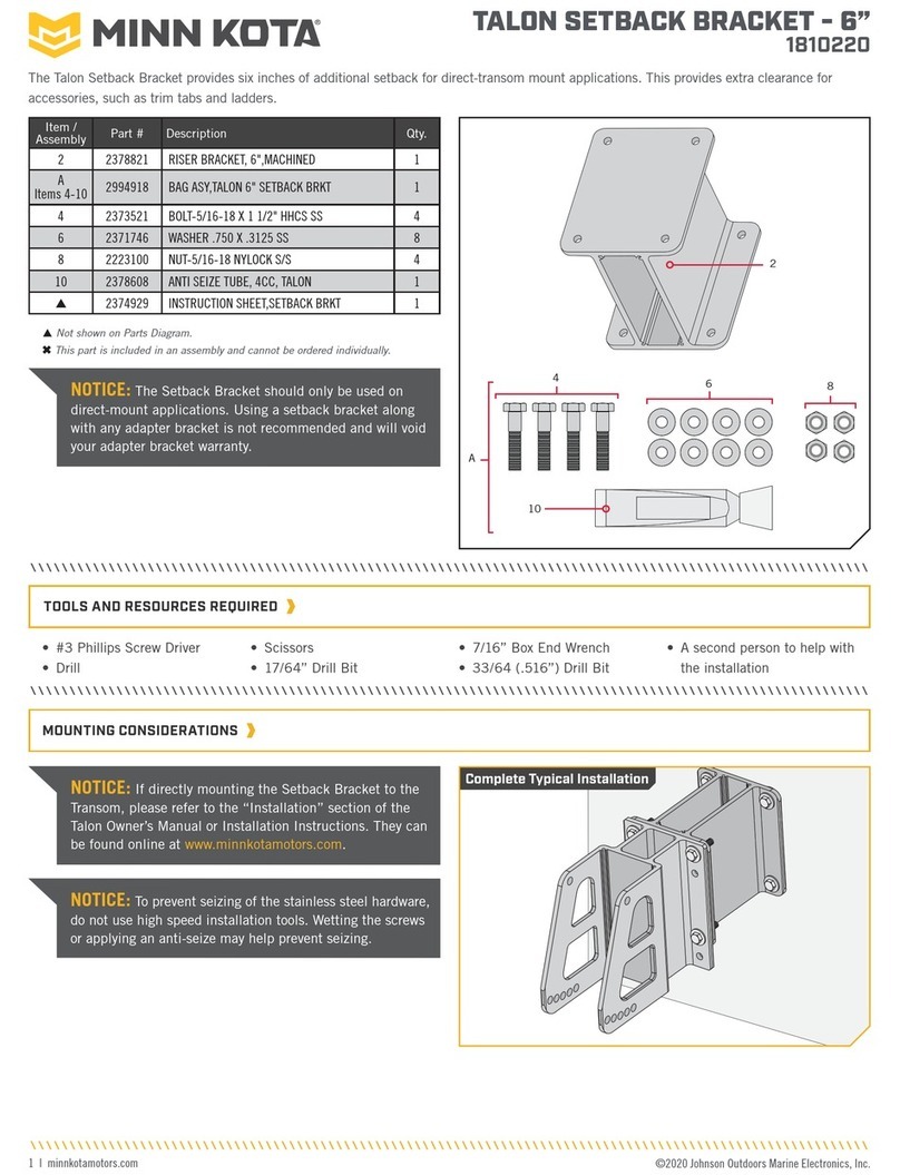
MINN KOTA
MINN KOTA 1810220 User manual
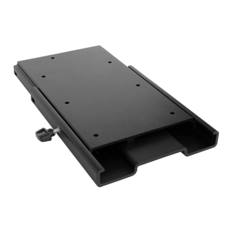
MINN KOTA
MINN KOTA MKA-16-03 User manual

MINN KOTA
MINN KOTA Raptor Port 1810361 User manual
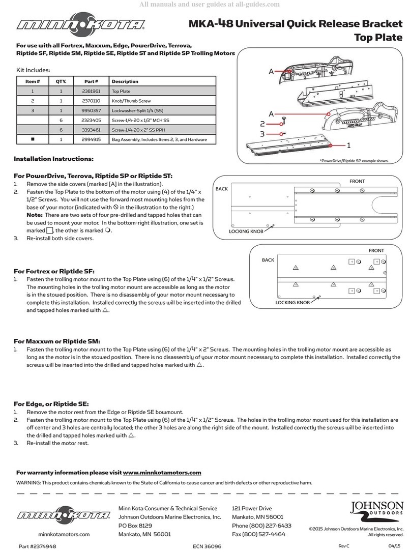
MINN KOTA
MINN KOTA MKA-48 User manual
MINN KOTA
MINN KOTA MKA-57 User manual
MINN KOTA
MINN KOTA MKA-23 User manual
MINN KOTA
MINN KOTA MKA-53 User manual

MINN KOTA
MINN KOTA MKA-47 User manual
MINN KOTA
MINN KOTA MKA-56 User manual
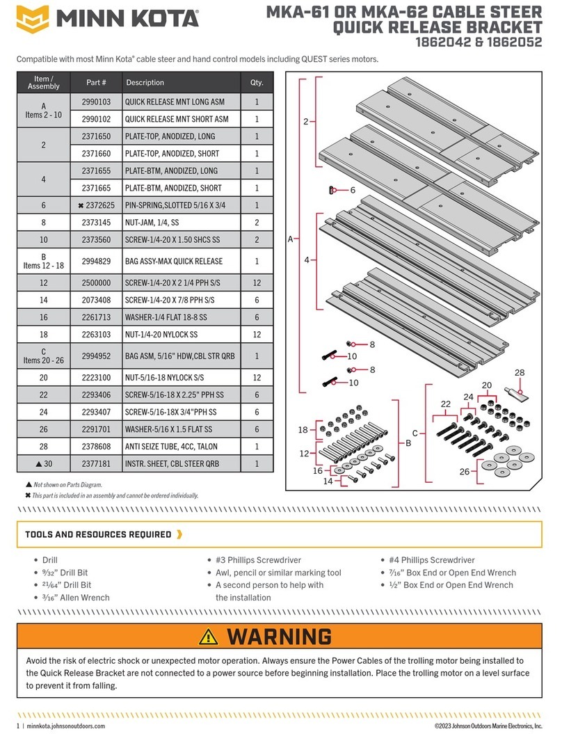
MINN KOTA
MINN KOTA MKA-61 User manual
