MINN KOTA MKA-56 User manual
1 | minnkota.johnsonoutdoors.com ©2023 Johnson Outdoors Marine Electronics, Inc.
MKA-56/RTA-55 COMPOSITE
QUICK RELEASE BRACKET
1854056 & 1854055
TOOLS AND RESOURCES REQUIRED
88
22
66
2424
1818
1414
2626
2020
CC
• #3 Phillips Screwdriver
• #4 Phillips Screwdriver
• Drill
• 13/32” Drill Bit
• 9/16” Box End or
Open End Wrench
• Needle-nose Pliers
(for Terrova and RT Terrova)
• Scissors
• Awl or similar marking tool
• A second person to help
with the installation
pNot shown on Parts Diagram.
The MKA-56 and RTA-55 are compatible with freshwater and saltwater electric-steer, bow-mount, QUEST series trolling motors, including the
Riptide Instinct, Ulterra, Riptide Terrova and Terrova.
BB
AA
1212
1212
1010
44
2222
1616
2828
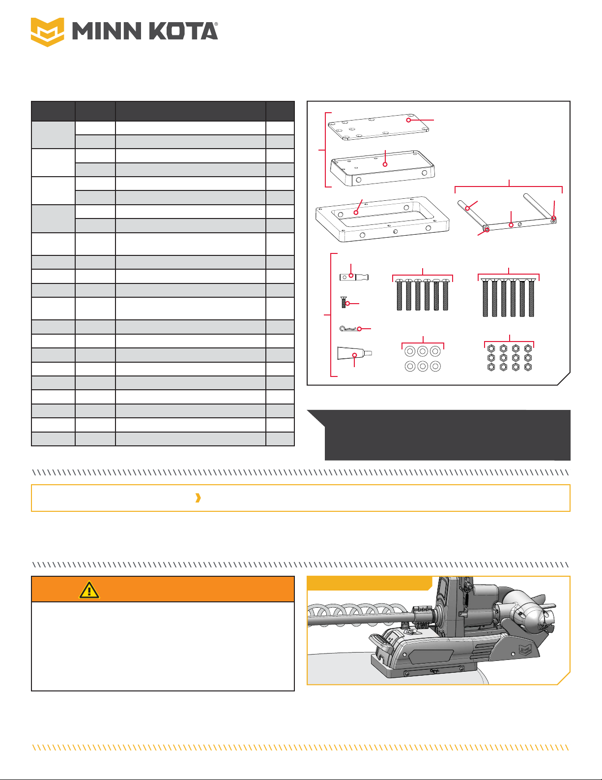
NOTICE: Images are a graphical representation and
may vary from your motor. Save the box! A template for
installation is printed on the inside of the box.
Item /
Assembly Part # Description Qty.
A
Items 2-4
2771686 INNER PUCK BL COMP QRB BLK *BLACK* 1
2771687 INNER PUCK BL COMP QRB WHT *WHITE* 1
22371686 PLATE,PUCK BACKUP,BLK ANDZD *BLACK* 1
2371687 PLATE, PUCK BACKUP, WHITE *WHITE* 1
42371695 PLATE-INNER, COMP FW BLK *BLACK* 1
2371696 PLATE-INNER, COMP SW WHT *WHITE* 1
62371697 PLATE-OUTER, COMP FW BLK *BLACK* 1
2371698 PLATE-OUTER, COMP SW WHT *WHITE* 1
B
Items 8-12 2770916 HANDLE ASM BL COMP QRB 1
8 2370916 HANDLE, HALF ROUND, ANODIZE 1
10 2372641 PIN-SHEAR, HANDLE 2
12 2383417 SCREW-5/16-18X3/4"BHCS 2
C
Items 14-28 2994946 BAG ASM,ELEC.STEER COMP QRB 1
14 2372634 PIN-PADLOCK, ALUM QRB 1
16 2383404 SCREW-1/4-20X7/8 PFH SS NYS 1
18 2260800 CLIP-HAIR SPRING,SS,MAX BG 1
20 2383485 SCREW-3/8-16 X 2 1/4 BHCS 6
22 2383490 SCREW-3/8-16 X 3" PFHCS SS 6
24 2351734 WASHER-3/8" FLAT SS 6
26 2383122 NUT 3/8-16 NYLON INST LOCKNUT 12
28 2378608 ANTI SEIZE TUBE, 4CC, TALON 1
p2374949 INSTRC. ELEC.STEER COMP QRB 1
Complete Typical Installation
WARNING
You are responsible for the safe and prudent operation of this
product. Minn Kota has designed this accessory to be a reliable
and convenient tool. Use only as directed and only for the
designed intent of the product. Installation should occur in an
area free from hazards and obstacles. This product does not
relieve you from the responsibility for safe operation.
2 | minnkota.johnsonoutdoors.com ©2023 Johnson Outdoors Marine Electronics, Inc.
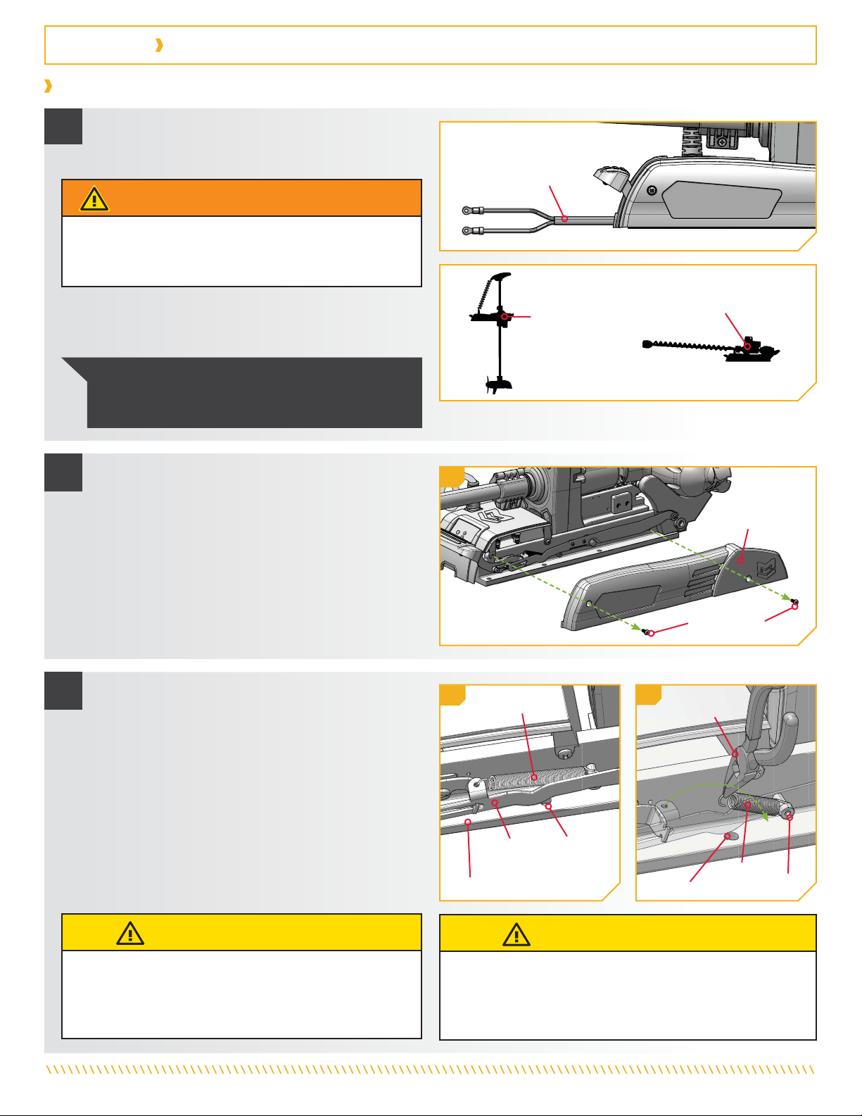
1. The MKA-56 and RTA-55 are compatible with freshwater
and saltwater electric-steer, bow-mount, QUEST series
trolling motors, including the Riptide Instinct QUEST, Ulterra
QUEST, Riptide Terrova QUEST and Terrova QUEST. The base
extrusion of the trolling motors may vary. Please note the
appearance of the base extrusion for each trolling motor.
2. It is recommended that the motor be mounted as close to
the centerline or keel of the boat as possible. Installation
of the Inner Plate requires the use of all six mounting bolts.
Mounting bolts spaced furthest apart will create the most
stability. Ensure that the mounting location is flat and that
the area under the mounting location is clear to drill holes
and install hardware. If there is not enough space on the boat
to install all six mounting bolts, this installation will require a
Boat Deck Reinforcement Kit (1854058).
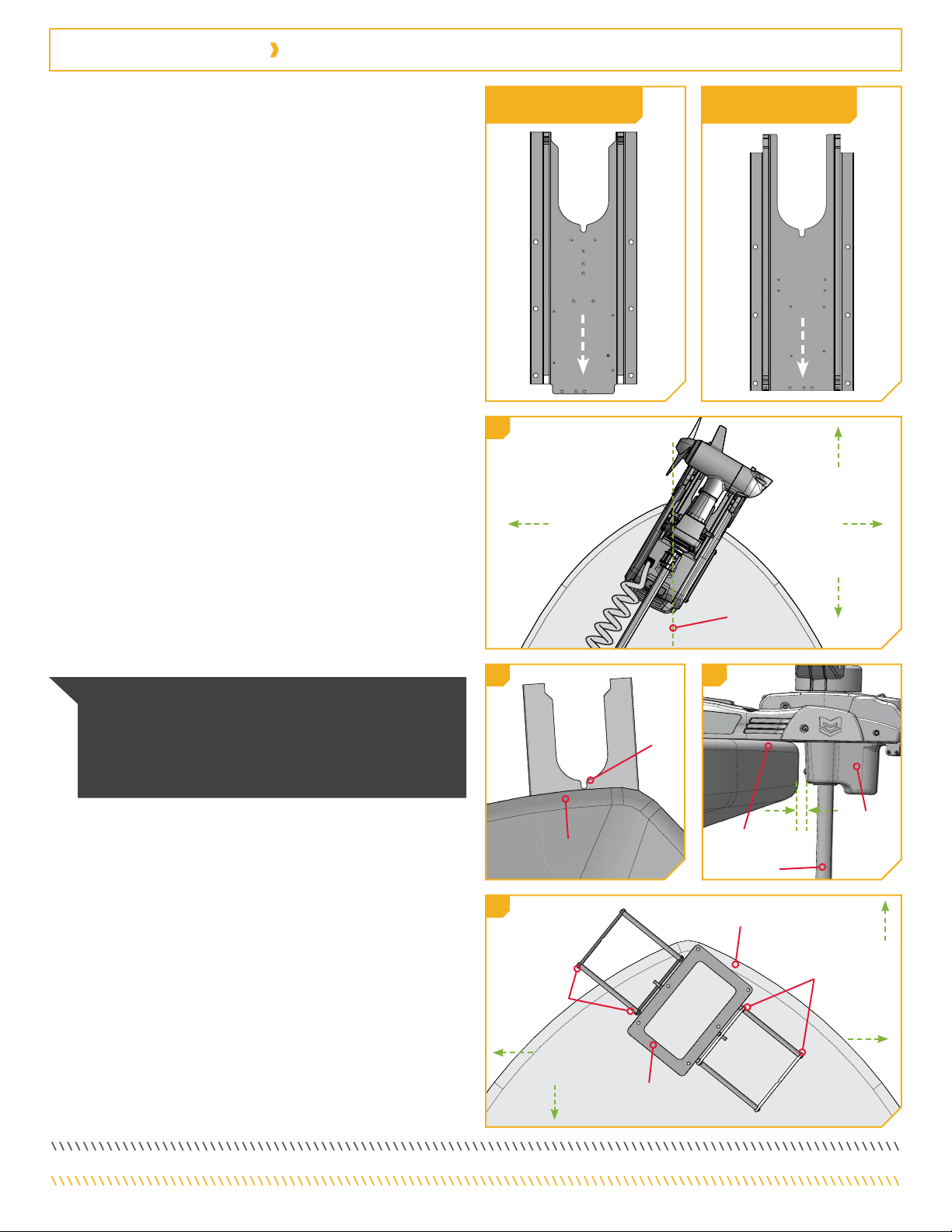
3. The motor must not encounter any obstructions as it is
lowered into the water or raised into the boat when stowed
and deployed. In the stowed position, place the motor so that
the slot in the Base Extrusion is positioned beyond the boat
Gunwale. For proper clearance, the entire slot must be visible
beyond the Gunwale. When the motor is deployed, there must
be a minimum required distance of 1½" between the Gunwale
and the bottom of the Steering Housing and Shaft.
GunwaleGunwale
SlotSlot
3
KeelKeel
2
1½"1½"
MinimumMinimum
GunwaleGunwale
ShaftShaft
SteeringSteering
HousingHousing
3
NOTICE: Ensure that the motor will not encounter any
obstructions when positioning the motor on and off the
composite bracket. The exact placement of the motor and
bracket may vary depending on the boat, boat deck, and
base extrusion to which the bracket is being mounted.
4. The bracket is designed so that the Handle Assembly can be
installed on either the Port or Starboard side to accommodate
clearances and personal preferences. Be sure that the Handle
Assembly will not encounter any obstructions on the bow of
the boat and can be pulled entirely out to release the plates
when mounted.
5. This installation requires the use of hardware included with
the trolling motor. The six Backup Bars (Part #2371796)
from the motor hardware bag assembly (Part #2994948)
will be needed.
6. With the motor in the stowed position, ensure there is enough
room for the Shaft and Control Head and that they do not
extend off the side of the boat.
Bow of BoatBow of Boat
HandleHandle
AssemblyAssembly
PositionsPositions
HandleHandle
AssemblyAssembly
PositionsPositions
Outer PlateOuter Plate
OutboardOutboard
InboardInboard
4
OutboardOutboard
StarboardStarboardPortPort
InboardInboard
StarboardStarboard
PortPort
InboardInboard InboardInboard
Ulterra QUEST
Riptide Instinct QUEST
Terrova QUEST
Riptide Terrova QUEST
MOUNTING CONSIDERATIONS
The MKA-56/RTA-55 composite brackets allow for bow-mount
trolling motors to be quickly mounted or removed from the boat
deck. The high-yield composite construction is super-strong and
impervious to corrosion. When checking motor clearance for a
mounting location, please give consideration to the following:
3 | minnkota.johnsonoutdoors.com ©2023 Johnson Outdoors Marine Electronics, Inc.
INSTALLATION
22c
Sideplate ScrewSideplate Screw
33e
CAUTION
When handling each Spring, always keep the spring tension
under control. Abruptly releasing the Spring while there is still
tension could damage it and cause it to release unpredictably.
CAUTION
When maneuvering each Spring, carefully handle the Spring
to avoid bending it. Do not grab the body of the Spring to
avoid pinching between the spring coils. Always grab by the
hooked end.
Needle-NoseNeedle-Nose
PliersPliers
SpringSpring
BoltBolt
SpringSpring
Mounting HoleMounting Hole
MountingMounting
HoleHole
Base ExtrusionBase Extrusion
SideSide
RailRail
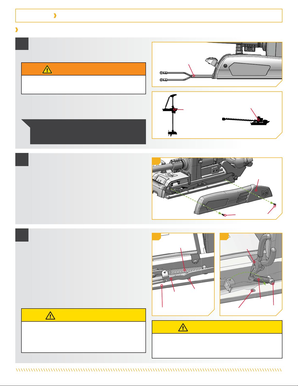
c. Remove the four Sideplate Screws using a #3 Phillips
Screwdriver. Two of these screws will be located on
each side of the mount.
d. Remove the Right Sideplate and the Left Sideplate to
expose the six mounting holes on the Base Extrusion.
e. The center mounting hole on either side of the Base
Extrusion is blocked by a Spring. One end of each
Spring must be disconnected in order to access the
mounting holes.
f. To disconnect the Spring, take a Needle-nose Pliers
and carefully grab the hooked end on the top half of
the Spring. Unhook it from the hole in the Side Rail
by pulling up. Guide it towards the bottom half of the
Spring still attached to the Base Extrusion and gently
set it down. Do not disconnect the end of the Spring
that is wrapped around a bolt. Unhook both Springs.
3f
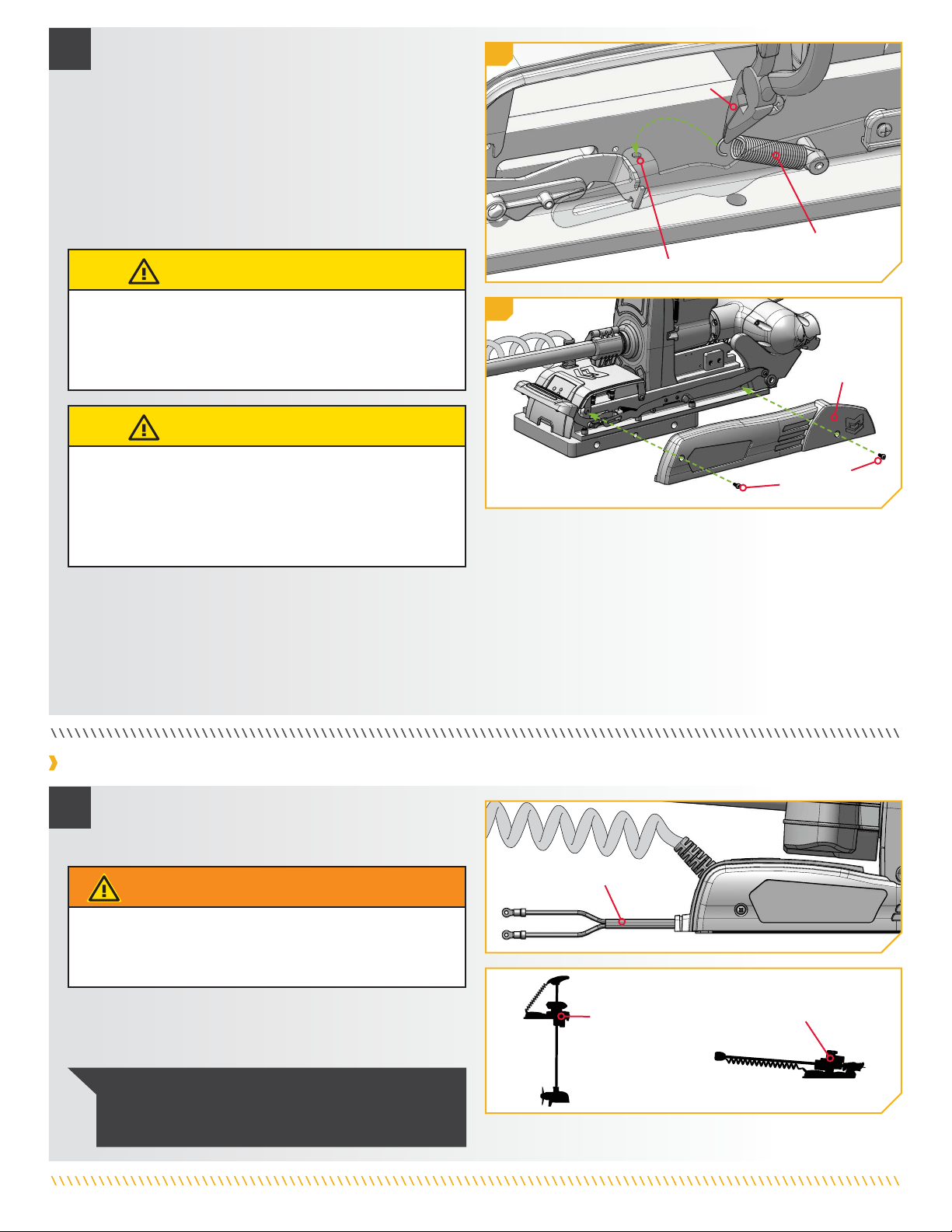
Installing the Outer Plate to a Terrova or Riptide Terrova
a. Make sure that the Power Cables from the battery
are disconnected or that the breaker, if equipped,
is “off.”
1
NOTICE: The trolling motor weighs up to 90lbs.
Minn Kota recommends having a second person help
with the installation.
DeployedDeployed StowedStowed
WARNING
Make sure that the Power Cables from the battery are
disconnected or that the breaker, if equipped, is “off.”
b. Place the mount on an elevated, level surface such
as a workbench or the tailgate of a pickup. The
motor should be in the stowed position.
SideplateSideplate
Power CablesPower Cables

4 | minnkota.johnsonoutdoors.com ©2023 Johnson Outdoors Marine Electronics, Inc.
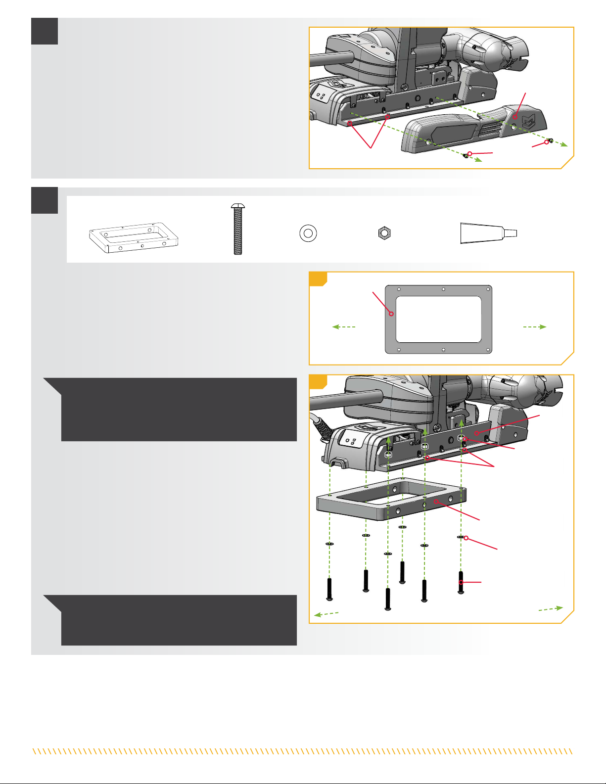
4ITEM(S) NEEDED
#26 x 6 #28 x 1#20 x 6#6 x 1 #24 x 6
NOTICE: To prevent seizing of the stainless steel
hardware, do not use high-speed installation tools.
Wetting the screws or applying an anti-seize (Item #28)
may help prevent seizing.
OuterOuter
PlatePlate
Mounting HolesMounting Holes
BaseBase
ExtrusionExtrusion
Button HeadButton Head
ScrewScrew
Nylock NutNylock Nut
Flat WasherFlat Washer
OutboardOutboard
InboardInboard
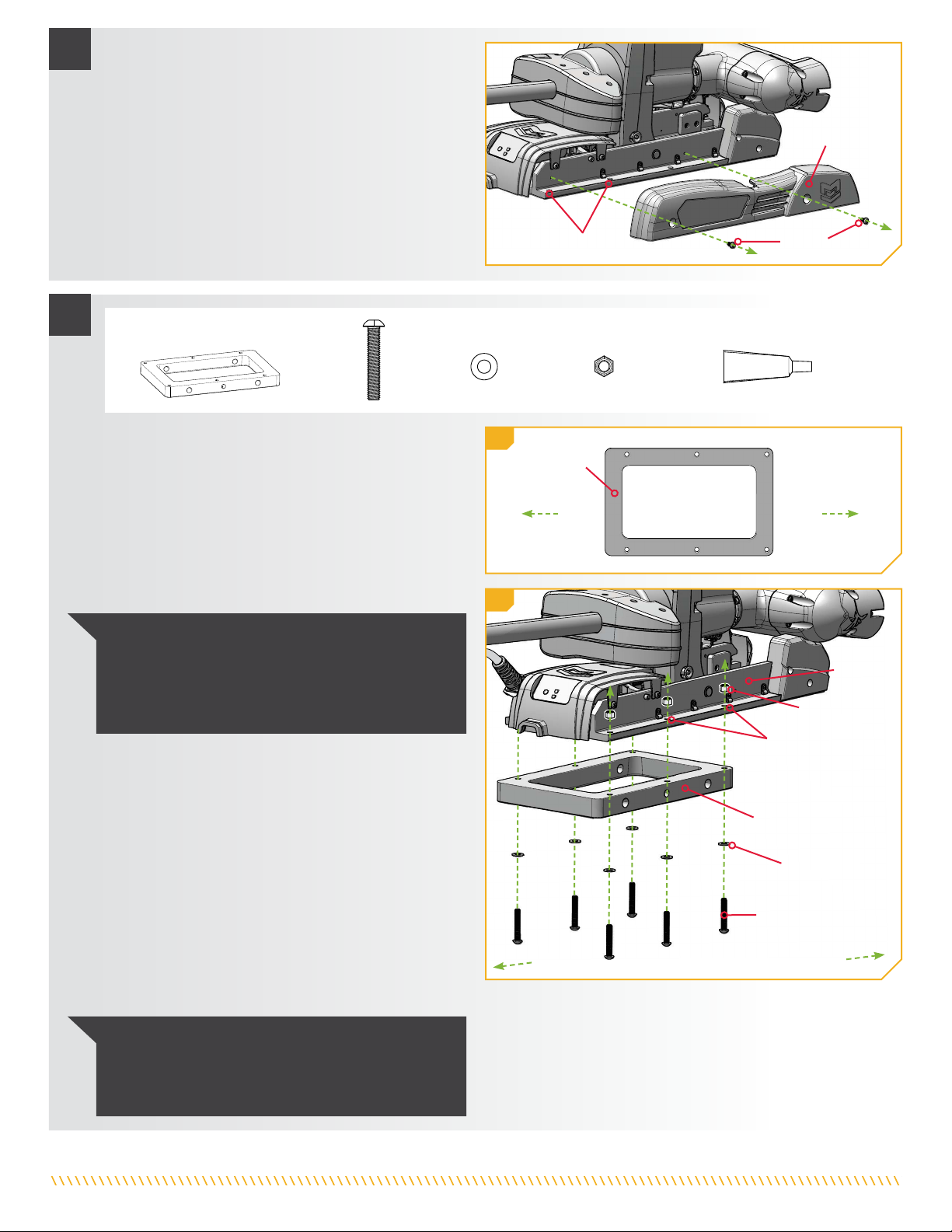
g. Place the Outer Plate (Item #6) against the bottom
of the Base Extrusion. The recessed holes in the
Outer Plate should face down toward the Boat
Deck. Position the Outer Plate so that the end
with Mounting Holes farthest from the edge points
inboard when mounted to the motor. Align the
Mounting Holes in the Outer Plate with the Mounting
Holes in the Base Extrusion that were exposed when
the sideplates and Springs were removed.
h. Use six each of the Button Head Screws (Item #20),
Flat Washers (Item #24), and Nylock Nuts (Item #26)
to secure the Outer Plate to the Base Extrusion. Put
anti-seize (Item #28) on all hardware. Place a Flat
Washer on each Button Head Screw, then install the
Screws up through the Outer Plate and into the Base
Extrusion. Place a Nylock Nut on the end of each
Screw. While holding each Nylock Nut with a 9/16"
Box End or Open End Wrench, use a #4 Phillips
Screwdriver to tighten each Screw. Tighten to
120 in-lbs. Make sure all hardware is secure.
OutboardOutboardInboardInboard
Outer PlateOuter Plate
4g
4h
NOTICE: Use extra care to avoid pinching and damaging
the sensor wires that run alongside the Base Extrusion
when installing and tightening the mounting hardware.

5 | minnkota.johnsonoutdoors.com ©2023 Johnson Outdoors Marine Electronics, Inc.
Installing the Outer Plate to an Ulterra or Riptide Instinct
Power CablesPower Cables
1
DeployedDeployed StowedStowed
a. Make sure that the Power Cables from the battery
are disconnected or that the breaker, if equipped,
is “off.”
WARNING
Make sure that the Power Cables from the battery are
disconnected or that the breaker, if equipped, is “off.”
NOTICE: The trolling motor weighs up to 90lbs.
Minn Kota recommends having a second person help
with the installation.
b. Place the mount on an elevated, level surface such
as a workbench or the tailgate of a pickup. The
motor should be in the stowed position.
55i
5j
SideplateSideplate
ScrewScrew
SideplateSideplate
Hole in Side RailHole in Side Rail
SpringSpring
Needle-Nose PliersNeedle-Nose Pliers
i. With the Outer Plate secured to the Base Extrusion,
reassemble the Springs that were disconnected. Use
a Needle-nose Pliers to grab the hooked end of the
loose Spring. Reconnect it by pulling it upwards and
hooking it in the hole on the Side Rail. The curved
end of the Spring should be reattached from the
top down. Make sure the Spring is not twisted when
reattaching it. Reattach the Spring on both the right
and left side of the Base Extrusion.
CAUTION
When maneuvering each Spring, carefully handle the Spring
to avoid bending it. Do not grab the body of the Spring to
avoid pinching between the spring coils. Always grab by the
hooked end.
CAUTION
When handling each Spring, always keep the spring tension
under control. Abruptly releasing the Spring while there is still
tension could damage it and cause it to release unpredictably.
j. With both Springs re-attached, replace the Right
Sideplate and Left Sideplate.
k. Replace the four Sideplate Screws using a #3 Phillips
Screwdriver. Two of these screws will be located on
each side of the mount. Hand tighten.
6 | minnkota.johnsonoutdoors.com ©2023 Johnson Outdoors Marine Electronics, Inc.
3
Outer PlateOuter Plate
Nylock NutNylock Nut
Mounting HolesMounting Holes
BaseBase
ExtrusionExtrusion
Button Head ScrewButton Head Screw
Flat WasherFlat Washer
OutboardOutboard
InboardInboard
3f
ITEM(S) NEEDED
#26 x 6 #28 x 1#20 x 6 #24 x 6
#6 x 1
e. Place the Outer Plate (Item #6) against the bottom
of the Base Extrusion. The recessed holes in the
Outer Plate should face down toward the Boat
Deck. Position the Outer Plate so that the end
with Mounting Holes farthest from the edge points
inboard when mounted to the motor. Align the
Mounting Holes in the Outer Plate with the Mounting
Holes in the Base Extrusion.
NOTICE: To prevent seizing of the stainless steel
hardware, do not use high-speed installation tools.
Wetting the screws or applying an anti-seize (Item #28)
may help prevent seizing.
NOTICE: Use extra care to avoid pinching and damaging
the sensor wires that run alongside the Base Extrusion
when installing and tightening the mounting hardware.
f. Use six each of the Button Head Screws (Item #20),
Flat Washers (Item #24), and Nylock Nuts (Item #26)
to secure the Outer Plate to the Base Extrusion. Put
anti-seize (Item #28) on all hardware. Place a Flat
Washer on each Button Head Screw, then install the
Screws up through the Outer Plate and into the Base
Extrusion. Place a Nylock Nut on the end of each
Screw. While holding each Nylock Nut with a 9/16"
Box End or Open End Wrench, use a #4 Phillips
Screwdriver to tighten each Screw. Tighten to
120 in-lbs. Make sure all hardware is secure.
2
SideplateSideplate
ScrewScrew
SideplateSideplate
Mounting HolesMounting Holes
c. Remove the four Sideplate Screws using a #3 Phillips
Screwdriver. Two of these screws will be located on
each side of the mount.
d. Remove the Right Sideplate and the Left Sideplate to
expose the six mounting holes in the Base Extrusion.
3e
OutboardOutboardInboardInboard
Outer PlateOuter Plate

7 | minnkota.johnsonoutdoors.com ©2023 Johnson Outdoors Marine Electronics, Inc.
ITEM(S) NEEDED
#B x 1 #14 x 1
1
Installing the Handle Assembly
a. Place the motor with the Outer Plate attached as
close to the centerline or keel of the boat as possible.
Review the mounting considerations at the beginning
of this document. Determine if the motor will be
mounted on the Port or Starboard side of the bow
and if the Handle Assembly (Item #B) will release
inboard or outboard. The side of the bracket that the
Handle Assembly is used on will determine which
side the Padlock Pin (Item #14) will be installed on.
b. With a mounting location determined and all
clearances confirmed, mark the side and rear edges
of the Outer Plate on the bow of the boat with an Awl
or similar marking tool. These markings will be used
to position a template for mounting the Inner Plate.
OutboardOutboard
InboardInboard
PortPort StarboardStarboard
Bow ofBow of
BoatBoat
KeelKeel
1a
44g
SideplateSideplate
ScrewScrew
SideplateSideplate
g. With the Outer Plate secured, replace the Right
Sideplate and Left Sideplate.
h. Replace the four Sideplate Screws using a #3 Phillips
Screwdriver. Two of these screws will be located on
each side of the mount.
OutboardOutboard
InboardInboard
1b
MarkingsMarkings
OuterOuter
PlatePlate
Bow of BoatBow of Boat
HandleHandle
AssemblyAssembly
PositionsPositions
HandleHandle
AssemblyAssembly
PositionsPositions
Outer PlateOuter Plate
OutboardOutboard
InboardInboard
StarboardStarboard
PortPort
1a

8 | minnkota.johnsonoutdoors.com ©2023 Johnson Outdoors Marine Electronics, Inc.
ITEM(S) NEEDED
#16 x 1 #28 x 1
Outer PlateOuter Plate
PadlockPadlock
PinPin
ScrewScrew
2
c. Once a position for the Handle Assembly is selected,
the Padlock Pin (Item #14) can be installed. Place the
Padlock Pin into the Outer Plate on the desired side
so that the larger diameter of the Pin installs into the
Outer Plate.
d. Take note of the two small screw holes on the bottom
of the Outer Plate. These holes do not pass all the
way through the Plate and are for the Screw that will
retain the Padlock Pin. Rotate the Padlock Pin so that
the hole in the Pin lines up with this screw hole.
e. Take the 1/4-20 X 7/8 Screw (Item #16) used to
secure the Padlock Pin and apply anti-seize
(Item #28) to the Screw. Insert the Screw into
the Outer Plate and Padlock Pin. Secure with a
#3 Phillips Screwdriver. Hole for PadlockHole for Padlock
Pin ScrewPin Screw
CAUTION
Ensure that the Screw is installed on the same side as the
Padlock Pin. Failure to retain the Padlock Pin with the
Screw will prevent the bracket and motor from securing. An
improperly secured motor may fall and cause injury.
#14 x 1
9 | minnkota.johnsonoutdoors.com ©2023 Johnson Outdoors Marine Electronics, Inc.
1
2
3
4
5
6
Drill (6) 25/64” DIA HOLES
Bow of BoatBow of Boat
TemplateTemplate
TemplateTemplate
InsideInside
of Boxof Box
MarkingsMarkings
DrillDrill
HolesHoles
Drill HolesDrill Holes
11a
1b
DrillDrill
HolesHoles
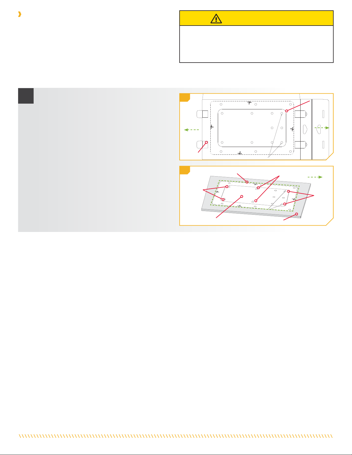
a. Take the box that the Quick Release Bracket came
in and carefully pull the glued edges apart. Open
the box so that it lays flat. A mounting template is
printed on the inside of the box to help locate, mark,
and drill mounting holes for the Inner Plate. Cut the
template out with Scissors and place it on the bow.
b. Align the template with the markings made on the
bow while checking handle and motor clearances.
Make sure that the direction of template matches
the direction of the Outer Plate as it is attached to
the motor. The end with six holes close together
should face outboard.
InboardInboard OutboardOutboard
OutboardOutboard
Installing the Inner Plate
The following instructions apply only to installations where the
MKA-56/RTA-55 Inner Plate is mounted directly to the boat deck.
If installing the Inner Plate with a Boat Deck Reinforcement Kit
(1854058), follow the installation instructions provided with the
Boat Deck Reinforcement Kit. Review the mounting considerations
to determine if a Boat Deck Reinforcement Kit is required.
Installing the Inner Plate to the boat deck will require the use of hardware included with the trolling motor. This installation will use six
Backup Bars (Part #2371796) from the mounting hardware bag assembly (Part #2994948).
CAUTION
An incorrectly secured trolling motor may cause injury.
Installation of the Inner Plate requires the use of all six mounting
bolts. Avoid injury from an incorrectly secured trolling motor by
following the installation instructions.
10 | minnkota.johnsonoutdoors.com ©2023 Johnson Outdoors Marine Electronics, Inc.
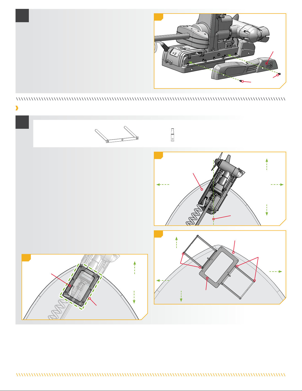
2
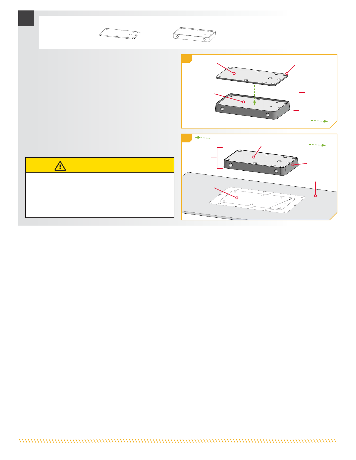
c. The Stiffener Plate (Item #2) is flush with the
Inner Plate (Item #4), and may not be immediately
noticable when removing the Quick Release Bracket
from the box. The top surface of the Inner Plate
is recessed to acommodate the placement of the
Stiffener Plate. This surface should face up.
d. Take the Stiffener Plate and place it into the recessed
surface of the Inner Plate. The Stiffener Plate should
be set on the Inner Plate so the recessed holes for
the Flat Head Screws are facing up.
e. Take note of the position of the template in relation to
the Inner Plate Assembly to ensure proper mounting.
ITEM(S) NEEDED
#2 x 1 #4 x 1
Inner PlateInner Plate Inner PlateInner Plate
AssemblyAssembly
Inner PlateInner Plate
AssemblyAssembly Inner PlateInner Plate
Boat DeckBoat Deck
TemplateTemplate
Stiffener PlateStiffener Plate
Stiffener PlateStiffener Plate
Recessed HoleRecessed Hole
OutboardOutboard
InboardInboard
OutboardOutboard
2d
2e
CAUTION
Failure to follow proper product installation may lead to
injury from product failure. To avoid injury from a damaged
product, ensure that the Stiffener Plate is present on the
Inner Plate before installing mounting hardware. Do not
install the Inner Plate without the Stiffener Plate.
11 | minnkota.johnsonoutdoors.com ©2023 Johnson Outdoors Marine Electronics, Inc.
3
Mark oneMark one
out of twoout of two
Mounting Hole Pattern OptionsMounting Hole Pattern Options
For additionalFor additional
security onlysecurity only
Mark oneMark one
out of twoout of two
MarkMark MarkMark
MarkMark MarkMark
InboardInboard
OutboardOutboard
TemplateTemplate
TemplateTemplate
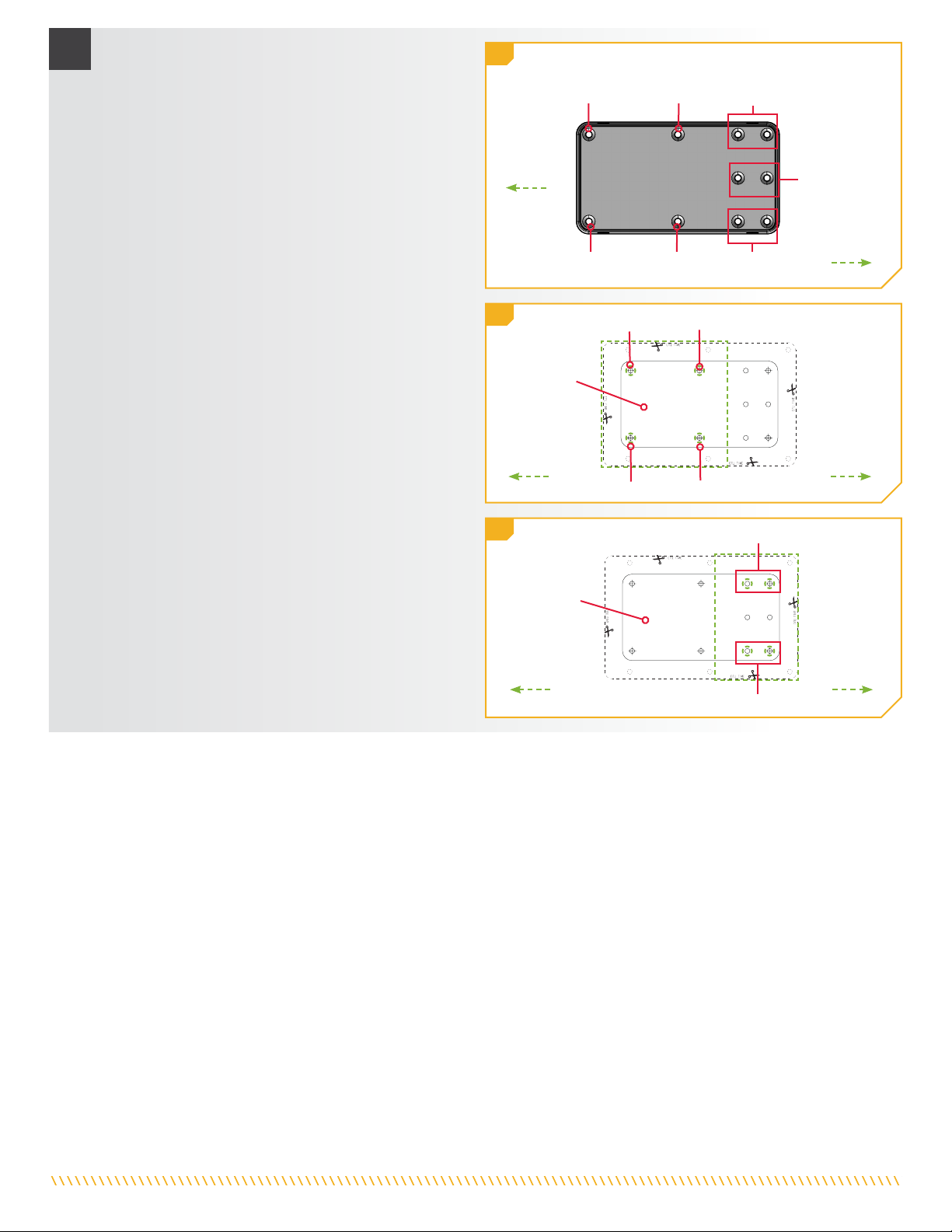
f. When mounting the Inner Plate Assembly, all six
mounting bolts must be used, with three bolts
on each side of the Plate. The template indicates
various mounting hole options to provide flexibility
and account for variances in bow shapes. If the
desired mounting location and mounting hole
pattern does not allow for all six mounting bolts, a
Boat Deck Reinforcement Kit (1854058) should be
used or a new mounting location selected.
g. Mark the boat deck with all four mounting holes on
the template that are the furthest inboard.
h. Look at the end of the template that is the furthest
outboard. There are six remaining mounting holes
on the template. The two holes in the center of this
pattern are for additional security only and should
not be used for primary installation of the Inner
Plate. Select a pattern from the remaining four
mounting holes. Mark one of these two holes on
each side of the Inner Plate. The chosen holes do
not need to be symmetrical, as long as one mounting
bolt is used on each side of the Inner Plate.
i. Use the template to mark the locations of the six
drill holes. Use a Drill with a 13/32" Drill Bit to drill
through the Boat Deck on the marked locations.
MarkMark MarkMark
MarkMark MarkMark
3g
3f
3h
InboardInboard
InboardInboard
OutboardOutboard
OutboardOutboard
Mark one out of twoMark one out of two
Mark one out of twoMark one out of two
12 | minnkota.johnsonoutdoors.com ©2023 Johnson Outdoors Marine Electronics, Inc.
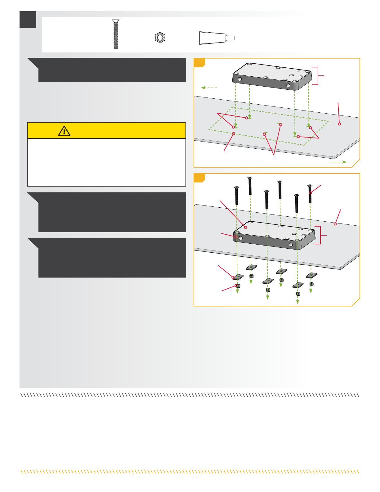
ITEM(S) NEEDED
#22 x 6
Inner PlateInner Plate
AssemblyAssembly
BackupBackup
BarBar
NylockNylock
NutNut
Flat HeadFlat Head
ScrewScrew
Drill HolesDrill Holes
InnerInner
PlatePlate
StiffenerStiffener
PlatePlate BoatBoat
DeckDeck
Boat DeckBoat Deck
#26 x 6 #28 x 1
4
4j
4k
DrillDrill
HolesHoles
j. Take the Inner Plate Assembly and place it on the
boat deck. Align the mounting holes in the Inner
Plate Assembly with the holes that were drilled in the
boat deck using the template.
NOTICE: To prevent seizing of the stainless steel
hardware, do not use high-speed installation tools.
Wetting the screws or applying an anti-seize (Item #28)
may help prevent seizing.
NOTICE: This installation requires the use of hardware
included with the trolling motor. The six Backup Bars
(Part #2371796) from the motor hardware bag assembly
(Part #2994948) are required.
NOTICE: Images are a graphical representation only
and may vary from your mounting position.
MarkingsMarkings Drill HolesDrill Holes
k. Insert a 3/8-16 x 3” Flat Head Screw (Item #22) into
each of the six drilled locations. Apply anti-seize
(Item #28) to all hardware. The Flat Head Screws
should pass through the Stiffener Plate and Inner
Plate that make up the Inner Plate Assembly, and
then pass through the boat deck.
l. Place a Backup Bar (Part #2371796) and then a
Nylock Nut (Item #26) at the end of each Screw.
While holding each Nylock Nut with a 9/16" Box
End or Open End Wrench, use a #4 Phillips
Screwdriver to tighten each Screw. Make sure all
hardware is secure.
InnerInner
PlatePlate
AssemblyAssembly
InboardInboard
OutboardOutboard
CAUTION
Failure to follow proper product installation may lead to
injury from product failure. To avoid injury from a damaged
product, ensure that the Stiffener Plate is present on the
Inner Plate before installing mounting hardware. Do not
install the Inner Plate without the Stiffener Plate.

Inner PlateInner Plate
BowBow
HandleHandle
AssemblyAssembly
Outer PlateOuter Plate
Padlock PinPadlock Pin
1
For warranty information, please visit minnkota.johnsonoutdoors.com.
Minn Kota Consumer & Technical Service
Johnson Outdoors Marine Electronics, Inc.
PO Box 8129
Mankato, MN 56001
121 Power Drive
Mankato, MN 56001
Phone (800) 227-6433
Fax (800) 527-4464
minnkota.johnsonoutdoors.com
©2023 Johnson Outdoors Marine Electronics, Inc.
All rights reserved.
Part #2374949 Rev B 05/23ECN 43074
Completing the Installation
a. Place the Outer Plate attached to the motor onto the
Inner Plate that was mounted to the bow of the boat.
To secure the Plates together, insert the Handle
Assembly on the same side as the Padlock Pin.
b. Insert the Hair Clip Pin (Item #18) into the Padlock
Pin to complete the assembly. The straight prong of
the Hair Clip should pass through the center of the
Padlock Pin, with the curved prong wrapped around
the outside of the Padlock Pin. The Padlock Pin
should sit in the middle arch of the Hair Clip Pin.
ITEM(S) NEEDED
#18 x 1
NOTICE: A padlock can be used in place of the Hair Clip
Pin to prevent motor theft. The diameter of the hole in
the Padlock Pin is 1/4".
CAUTION
Before using or transporting the trolling motor, always make
sure that the Handle Assembly is fully inserted and retained
by the Hair Clip Pin. Failure to insert and secure the Handle
Assembly may result in injury from a falling motor.
Hair Clip PinHair Clip Pin
Padlock PinPadlock Pin
1a
1b

14 | minnkota.johnsonoutdoors.com ©2023 Johnson Outdoors Marine Electronics, Inc.
SUPPORT À DÉGAGEMENT RAPIDE
EN COMPOSITE MKA-56/RTA-55
1854056 et 1854055
OUTILS ET RESSOURCES NÉCESSAIRES
Les MKA-56 et RTA-55 sont compatibles avec les moteurs de pêche à la traîne de la série QUEST à direction électrique et à montage sur proue
d’eau douce et d’eau salée, notamment les Riptide Instinct, Ulterra, Riptide Terrova et Terrova.
AVIS : Les images sont une représentation graphique et peuvent
être différentes de votre moteur. Conservez cette boîte! Un
gabarit pour l’installation est imprimé sur l’intérieur de la boîte.
pNon affiché sur le schéma des pièces.
• Tournevis cruciforme nº 3
• Tournevis cruciforme nº 4
• Ciseaux
• Perceuse
• Mèche de 13/32 po
(10,32 mm)
• Clé polygonale/ouverte de
9/16 po (14,28 mm)
• Pince à bec pointu
(pour Terrova et RT Terrova)
• Poinçon ou autre outil de
marquage semblable
• Une deuxième personne
pour vous aider avec
l’installation
Installation complète typique
AVERTISSEMENT
Vous êtes responsable de l’utilisation sûre et prudente de ce
produit. Minn Kota a conçu cet accessoire pour être un outil
fiable et pratique. Utiliser uniquement comme indiqué et
uniquement pour l’intention prévue du produit. L’installation
doit avoir lieu dans une zone exempte de dangers et d’obstacles.
Ce produit ne vous exonère pas de la responsabilité de naviguer
en toute sécurité.
88
22
66
2424
1818
1414
2626
2020
CC
BB
AA
1212
1212
1010
44
2222
1616
2828
Article/
Ensemble Nº de
pièce Description Qté
A
Articles 2 à 4
2771686 INNER PUCK BL COMP QRB BLK *NOIR* 1
2771687 INNER PUCK BL COMP QRB WHT *BLANC* 1
22371686 PLATE,PUCK BACKUP,BLK ANDZD *NOIR* 1
2371687 PLATE, PUCK BACKUP, WHITE *BLANC* 1
42371695 PLATE-INNER, COMP FW BLK *NOIR* 1
2371696 PLATE-INNER, COMP SW WHT *BLANC* 1
62371697 PLATE-OUTER, COMP FW BLK *NOIR* 1
2371698 PLATE-OUTER, COMP SW WHT *BLANC* 1
B
Articles 8 à 12 2770916 HANDLE ASM BL COMP QRB 1
8 2370916 HANDLE, HALF ROUND, ANODIZE 1
10 2372641 PIN-SHEAR, HANDLE 2
12 2383417 SCREW-5/16-18X3/4"BHCS 2
C
Articles 14 à 28 2994946 BAG ASM,ELEC.STEER COMP QRB 1
14 2372634 PIN-PADLOCK, ALUM QRB 1
16 2383404 SCREW-1/4-20X7/8 PFH SS NYS 1
18 2260800 CLIP-HAIR SPRING,SS,MAX BG 1
20 2383485 SCREW-3/8-16 X 2 1/4 BHCS 6
22 2383490 SCREW-3/8-16 X 3" PFHCS SS 6
24 2351734 WASHER-3/8" FLAT SS 6
26 2383122 NUT 3/8-16 NYLON INST LOCKNUT 12
28 2378608 ANTI SEIZE TUBE, 4CC, TALON 1
p2374949 INSTRC. ELEC.STEER COMP QRB 1

15 | minnkota.johnsonoutdoors.com ©2023 Johnson Outdoors Marine Electronics, Inc.
Plat-bordPlat-bord
FenteFente
3
QuilleQuille
2
MinimumMinimum
de 1,5 pode 1,5 po
(3,8 cm)(3,8 cm)
Plat-bordPlat-bord
ArbreArbre
Boîtier deBoîtier de
directiondirection
3
AVIS : Assurez-vous que le moteur ne rencontrera pas
d’obstacles lorsque vous le placez sur le support en composite
et que vous l’enlevez. L’emplacement précis du moteur et
du support peut varier selon le bateau, le pont du bateau et
l’extrusion de la base sur laquelle est monté le support.
Proue du bateauProue du bateau
Positions dePositions de
l’ensemblel’ensemble
poignéepoignée
Positions dePositions de
l’ensemblel’ensemble
poignéepoignée
Plaque externePlaque externe
Hors-bordHors-bord
En-bordEn-bord
4
Hors-bordHors-bord
TribordTribord
BâbordBâbord
En-bordEn-bord
TribordTribord
BâbordBâbord
En-bordEn-bord En-bordEn-bord
FACTEURS DE MONTAGE
1. Les MKA-56 et RTA-55 sont compatibles avec les moteurs de
pêche à la traîne QUEST à direction électrique et à montage sur
étrave d’eau douce et d’eau salée, notamment les Riptide Instinct
QUEST, Ulterra QUEST, Riptide Terrova QUEST et Terrova
QUEST. L’extrusion de la base des moteurs de pêche à la traîne
peut varier. Veuillez noter l’apparence de l’extrusion de la base
pour chaque moteur de pêche à la traîne.
2. Il est recommandé que le moteur soit monté aussi près que
possible de l’axe ou de la quille du bateau. L’installation de la
plaque interne nécessite l’utilisation des six boulons de montage.
Monter les boulons aussi éloignés l’un de l’autre que possible
créera la plus grande stabilité. Assurez-vous que l’emplacement de
montage est à plat et que la zone sous l’emplacement de montage
est dégagée pour percer les trous et installer la quincaillerie. S’il
n’y a pas suffisamment d’espace sur le bateau pour installer les six
boulons de montage, cette installation nécessitera une trousse de
renforcement du pont du bateau (1854058).
3. Le moteur ne doit rencontrer aucune obstruction lorsqu’il est
abaissé dans l’eau ou monté dans le bateau pour arrimage ou
déploiement. En position arrimée, placez le moteur de sorte que
la fente de l’extrusion de la base soit positionnée au-delà du plat-
bord du bateau. Le dégagement est approprié lorsque la totalité
de la fente est visible au-delà du plat-bord. Lorsque le moteur est
déployé, il doit y avoir une distance minimale requise de 1½ po
(3,81 cm) entre le plat-bord et le fond du boîtier de direction et
de l’arbre.
4. Le support est conçu afin que l’ensemble de poignée puisse
être placé à bâbord ou à tribord selon les dégagements et
les préférences personnelles. Assurez-vous qu’il n’y a pas
d’obstruction à l’ensemble poignée sur la proue du bateau et qu’il
peut être entièrement sorti pour dégager les plaques lorsqu’elles
sont montées.
5. Cette installation nécessite l’utilisation de la quincaillerie incluse
avec votre moteur de pêche à la traîne. Les six barres d’appui
(pièce nº 2371796) du lot sous emballage de quincaillerie du
moteur (pièce nº 2994948) seront nécessaires.
6. Le moteur en position d’arrimage, assurez-vous qu’il y a
suffisamment d’espace pour l’arbre et la tête de contrôle et qu’ils
ne s’étendent pas au-delà du bateau.
Ulterra QUEST
Riptide Instinct QUEST
Terrova QUEST
Riptide Terrova QUEST
Le support composite MKA-56/RTA-55 permet de monter ou de
démonter rapidement les moteurs de pêche à la traîne sur le pont du
bateau. La construction en composite extrêmement performant est
ultra robuste et insensible à la corrosion. Lors de la vérification du
dégagement du moteur pour un emplacement de montage, veuillez
tenir compte de ce qui suit :
16 | minnkota.johnsonoutdoors.com ©2023 Johnson Outdoors Marine Electronics, Inc.
INSTALLATION
22c
Vis de plaqueVis de plaque
latéralelatérale
33e
ATTENTION
Lorsque vous manipulez chaque ressort, gardez toujours la tension
du ressort sous contrôle. Relâcher brusquement le ressort alors
qu’il y a encore de la tension pourrait l’endommager et faire en
sorte que ses mouvements soient imprévisibles.
ATTENTION
Lorsque vous manipulez chaque ressort, manipulez-le avec
précaution pour éviter de le plier. Ne saisissez pas le corps
du ressort pour éviter de pincer entre les spires du ressort.
Saisissez toujours par l’extrémité à crochet.
Pince à becPince à bec
pointupointu
RessortRessort BoulonBoulon
RessortRessort
Trou de montageTrou de montage
Trou deTrou de
montagemontage
Extrusion de la baseExtrusion de la base
RailRail
latérallatéral
c. Retirez les quatre vis de la plaque latérale en utilisant
un tournevis cruciforme nº 3. Deux de ces vis seront
situées de chaque côté du support.
d. Retirez la plaque latérale droite et la plaque latérale
gauche pour exposer les six trous de montage sur
l’extrusion de la base.
e. Le trou de montage central de chaque côté de
l’extrusion de la base est bloqué par un ressort. Une
extrémité de chaque ressort doit être déconnectée
pour accéder aux trous de montage.
f. Pour déconnecter le ressort, prenez une pince à bec
pointu et saisissez soigneusement l’extrémité à crochet
sur la moitié supérieure du ressort. Décrochez-la du
trou du rail latéral en la tirant vers le haut. Guidez-la
vers la moitié inférieure du ressort toujours attaché à
l’extrusion de la base et déposez-la doucement. Ne
déconnectez pas l’extrémité du ressort qui est enroulée
autour d’un boulon. Décrochez les deux ressorts.
3f
Installation de la plaque externe sur un Terrova ou un Riptide Terrova
a. Assurez-vous que les câbles d’alimentation de la
batterie sont déconnectés, ou que le disjoncteur, le cas
échéant, est en position « arrêt ».
1
AVIS : Le moteur de pêche à la traîne pèse jusqu’à 90 lb
(40,8 kg). Minn Kota recommande d’obtenir l’aide d’une
deuxième personne pour l’installation.
DéployéDéployé ArriméArrimé
AVERTISSEMENT
Assurez-vous que les câbles d’alimentation de la batterie sont
déconnectés, ou que le disjoncteur, le cas échéant, est en
position « arrêt ».
b. Placez le support sur une surface élevée, de niveau,
comme un établi ou le hayon d’une camionnette. Le
moteur devrait être en position arrimée.
Plaque latéralePlaque latérale
Câbles d’alimentationCâbles d’alimentation

17 | minnkota.johnsonoutdoors.com ©2023 Johnson Outdoors Marine Electronics, Inc.
4ARTICLE(S) REQUIS
#26 x 6 #28 x 1#20 x 6#6 x 1 #24 x 6
AVIS : Pour prévenir le grippage de la quincaillerie en
acier inoxydable, n’utilisez pas d’outils haute vitesse
pour l’installation. Mouiller les vis ou appliquer un
produit antigrippant (article nº 28) peut aider à prévenir
qu’elles grippent.
Trous de montageTrous de montage
ExtrusionExtrusion
de la basede la base
Vis à têteVis à tête
ronderonde
Écrou NylockÉcrou Nylock
Rondelle plateRondelle plate
Hors-bordHors-bord
En-bordEn-bord
g. Placez la plaque externe (article nº 6) contre le fond
de l’extrusion de la base. Les trous encastrés dans la
plaque extérieure doivent être orientés vers le bas,
vers le pont du bateau. Positionnez la plaque externe
de manière à ce que l’extrémité avec les trous de
montage les plus éloignés du bord pointe vers l’en-
bord lorsqu’elle est montée sur le moteur. Alignez
les trous de montage dans la plaque externe avec
les trous de montage dans l’extrusion de la base qui
ont été exposés lorsque les plaques latérales et les
ressorts ont été retirés.
h. Utilisez six vis à tête ronde (article nº 20), les
rondelles plates (article nº 24) et les écrous
Nylock (article nº 26) pour fixer la plaque externe
à l’extrusion de la base. Appliquez un produit
antigrippant (article nº 28) sur toute la quincaillerie.
Placez une rondelle plate sur chaque vis à tête ronde,
puis installez les vis à travers la plaque externe et
dans l’extrusion de la base. Tout en maintenant
chaque écrou Nylock à l’aide d’une clé polygonale
ou d’une clé plate 9/16 po (14,28 mm), utilisez
un tournevis cruciforme nº 4 pour serrer chaque
vis. Serrez à un couple de 120 po-lb (13,56 Nm).
Assurez-vous que toute la quincaillerie est bien fixée.
Hors-bordHors-bordEn-bordEn-bord
PlaquePlaque
externeexterne
4g
4h
AVIS : Faites preuve de vigilance pour éviter de pincer
ou d’endommager les fils de capteur qui longent
l’extrusion de la base lors de l’installation et du serrage
de la quincaillerie de montage.
Plaque externePlaque externe
18 | minnkota.johnsonoutdoors.com ©2023 Johnson Outdoors Marine Electronics, Inc.
Installation de la plaque externe sur un Ulterra ou un Riptide Instinct
Câbles d’alimentationCâbles d’alimentation
1
DéployéDéployé ArriméArrimé
a. Assurez-vous que les câbles d’alimentation de la
batterie sont déconnectés, ou que le disjoncteur, le
cas échéant, est en position « arrêt ».
AVERTISSEMENT
Assurez-vous que les câbles d’alimentation de la batterie
sont déconnectés, ou que le disjoncteur, le cas échéant, est
en position « arrêt ».
AVIS : Le moteur de pêche à la traîne pèse jusqu’à 90 lb
(40,8 kg). Minn Kota recommande d’obtenir l’aide d’une
deuxième personne pour l’installation.
b. Placez le support sur une surface élevée, de niveau,
comme un établi ou le hayon d’une camionnette. Le
moteur devrait être en position arrimée.
55i
5j
Vis de plaqueVis de plaque
latéralelatérale
PlaquePlaque
latéralelatérale
Trou dans le rail latéralTrou dans le rail latéral
RessortRessort
Pince à bec pointuPince à bec pointu
i. La plaque externe fixée à l’extrusion de la base,
réassemblez les ressorts qui ont été déconnectés.
Utilisez une pince à bec pointu pour saisir l’extrémité
à crochet du ressort libre. Reconnectez-le en le
tirant vers le haut et en l’accrochant dans le trou
du rail latéral. L’extrémité courbée du ressort doit
être rattachée de haut en bas. Assurez-vous que
le ressort n’est pas tordu lors de sa réinstallation.
Rattachez le ressort sur les côtés droit et gauche de
l’extrusion de la base.
ATTENTION
Lorsque vous manipulez chaque ressort, manipulez-le avec
précaution pour éviter de le plier. Ne saisissez pas le corps
du ressort pour éviter de pincer entre les spires du ressort.
Saisissez toujours par l’extrémité à crochet.
ATTENTION
Lorsque vous manipulez chaque ressort, gardez toujours
la tension du ressort sous contrôle. Relâcher brusquement
le ressort alors qu’il y a encore de la tension pourrait
l’endommager et faire en sorte que ses mouvements
soient imprévisibles.
j. Les deux ressorts réinstallés, rattachez la plaque
latérale droite et la plaque latérale gauche.
k. Replacez les quatre vis de la plaque latérale en
utilisant un tournevis cruciforme nº 3. Deux de ces
vis seront situées de chaque côté du support. Serrez
à la main.
19 | minnkota.johnsonoutdoors.com ©2023 Johnson Outdoors Marine Electronics, Inc.
3
Plaque externePlaque externe
Écrou NylockÉcrou Nylock
Trous de montageTrous de montage
ExtrusionExtrusion
de la basede la base
Vis à tête rondeVis à tête ronde
Rondelle plateRondelle plate
Hors-bordHors-bord
En-bordEn-bord
3f
ARTICLE(S) REQUIS
#26 x 6 #28 x 1#20 x 6 #24 x 6
#6 x 1
e. Placez la plaque externe (article nº 6) contre le fond
de l’extrusion de la base. Les trous encastrés dans
la plaque extérieure doivent être orientés vers le
bas, vers le pont du bateau. Positionnez la plaque
externe de manière à ce que l’extrémité avec les
trous de montage les plus éloignés du bord pointe
vers l’en-bord lorsqu’elle est montée sur le moteur.
Alignez les trous de montage dans la plaque externe
avec ceux de l’extrusion de la base.
AVIS : Pour prévenir le grippage de la quincaillerie en
acier inoxydable, n’utilisez pas d’outils haute vitesse
pour l’installation. Mouiller les vis ou appliquer un
produit antigrippant (article nº 28) peut aider à prévenir
qu’elles grippent.
AVIS : Faites preuve de vigilance pour éviter de pincer
ou d’endommager les fils de capteur qui longent
l’extrusion de la base lors de l’installation et du serrage
de la quincaillerie de montage.
f. Utilisez six vis à tête ronde (article nº 20), les
rondelles plates (article nº 24) et les écrous
Nylock (article nº 26) pour fixer la plaque externe
à l’extrusion de la base. Appliquez un produit
antigrippant (article nº 28) sur toute la quincaillerie.
Placez une rondelle plate sur chaque vis à tête ronde,
puis installez les vis à travers la plaque externe et
dans l’extrusion de la base. Tout en maintenant
chaque écrou Nylock à l’aide d’une clé polygonale
ou d’une clé plate 9/16 po (14,28 mm), utilisez
un tournevis cruciforme nº 4 pour serrer chaque
vis. Serrez à un couple de 120 po-lb (13,56 Nm).
Assurez-vous que toute la quincaillerie est bien fixée.
2
Vis deVis de
plaqueplaque
latéralelatérale
Plaque latéralePlaque latérale
Trou de montageTrou de montage
c. Retirez les quatre vis de la plaque latérale en
utilisant un tournevis cruciforme nº 3. Deux de ces
vis seront situées de chaque côté du support.
d. Retirez la plaque latérale droite et la plaque latérale
gauche pour exposer les six trous de montage dans
l’extrusion de la base.
3e
Hors-bordHors-bordEn-bordEn-bord
PlaquePlaque
externeexterne
20 | minnkota.johnsonoutdoors.com ©2023 Johnson Outdoors Marine Electronics, Inc.
ARTICLE(S) REQUIS
#B x 1 #14 x 1
1
Installation de l’ensemble poignée
a. Placez le moteur avec la plaque externe attachée le
plus près possible de l’axe ou de la quille du bateau.
Passez en revue les facteurs de montage au début de
ce document. Déterminez si le moteur sera monté sur
le côté bâbord ou tribord de la proue et si l’ensemble
poignée (article nº B) sera libéré vers l’en-bord ou le
hors-bord. Le côté du support sur lequel l’ensemble
poignée est utilisé déterminera le côté où sera
installée la goupille cadenas (article nº 14).
b. Une fois un emplacement de montage déterminé et
tous les dégagements confirmés, marquez les bords
latéraux et arrière de la plaque externe sur la proue
du bateau avec un poinçon ou un outil similaire. Ces
marques seront utilisées pour positionner un gabarit
pour le montage de la plaque interne.
Hors-bordHors-bord
En-bordEn-bord
BâbordBâbord TribordTribord
Proue duProue du
bateaubateau
QuilleQuille
1a
44g
Vis de plaqueVis de plaque
latéralelatérale
PlaquePlaque
latéralelatérale
g. Une fois la plaque externe fixée, replacez la plaque
latérale droite et la plaque latérale gauche.
h. Replacez les quatre vis de la plaque latérale en
utilisant un tournevis cruciforme nº 3. Deux de ces
vis seront situées de chaque côté du support.
Hors-bordHors-bord
En-bordEn-bord
1b
MarquesMarques
PlaquePlaque
externeexterne
Proue du bateauProue du bateau
Positions dePositions de
l’ensemblel’ensemble
poignéepoignée
Positions dePositions de
l’ensemblel’ensemble
poignéepoignée
PlaquePlaque
externeexterne
Hors-bordHors-bord
En-bordEn-bord
TribordTribord
BâbordBâbord
1a
This manual suits for next models
3
Table of contents
Languages:
Other MINN KOTA TV Mount manuals

MINN KOTA
MINN KOTA MKA-47 User manual

MINN KOTA
MINN KOTA MKA-57 User manual

MINN KOTA
MINN KOTA MKA-53 User manual

MINN KOTA
MINN KOTA MKA-48 User manual

MINN KOTA
MINN KOTA MKA-48 User manual

MINN KOTA
MINN KOTA 1810220 User manual

MINN KOTA
MINN KOTA Raptor Port 1810361 User manual

MINN KOTA
MINN KOTA MKA-51 User manual

MINN KOTA
MINN KOTA TALON User manual

MINN KOTA
MINN KOTA MKA-23 User manual


