MINN KOTA TALON User manual

TILT BRACKET
Owner's Manual
Compatible with all Talon Shallow Water Anchor Models.

EXAMPLE
Model: _________________________________________________________________________________________________________________
Serial Number: __________________________________________________________________________________________________________
Purchase Date: __________________________________________________________________________________________________________
Store Where Purchased: __________________________________________________________________________________________________
REGISTRATION
Remember to keep your receipt and immediately register your
Talon. To receive all the benefits of your product warranty
please fill out and mail the registration card, you may also
register your product online at minnkotamotors.com.
SERIAL NUMBER
Your Minn Kota 11-character serial number is very important. It
helps to determine the specific model and year of manufacture.
When contacting Consumer Service or registering your product,
you will need to know your product’s serial number. We
recommend that you write the serial number down so that you
have it available for future reference.
TALON INFORMATION (For Consumer Reference Only)
NOTICE: The serial number on your Tilt Bracket is
located on the inside of the bracket, near the latch pin.
Made by Minn Kota
Johnson Outdoors
Marine Electronics, Inc.
121 Power Drive
Mankato, MN 56001 USA
Trolling Motors
Produced in 2012
Talon Tilt Bracket
MODEL 1810222
SER NO M365 MK12345
EXAMPLE
THANK YOU
Your new Talon Tilt Bracket is designed to allow easy tilting when needed. These conditions include low hanging obstacles or backing in
and out of low overhead clearances. The tilt feature may also be used to extend your Talon for easy cleaning purposes.
2 | minnkotamotors.com ©2019 Johnson Outdoors Marine Electronics, Inc.
INTRODUCTION

Please thoroughly read the user manual. Follow all instructions and heed all safety considerations. Use of this product is only permitted
for persons that have read and understood these instructions. Minors may use this product only under adult supervision.
WARNING
It is recommended to only use Johnson Outdoors approved accessories with your Talon. Using non-approved accessories including
those used to mount or control your product may cause damage, unexpected operation and injury. Be sure to use the product and
all approved accessories, including remotes, safely and in the manner directed to avoid accidental or unexpected operation. Keep
all factory installed parts in place including motor, electronic and accessory covers, enclosures and guards. Failure to adhere to this
warning may affect your warranty.
1. The Talon Tilt Bracket can only be installed with the use of a Talon Adapter Bracket (Jack Plate or sandwich style) to ensure proper
clearances from the top cap of the boat. Direct transom mount applications will not have proper clearance.
CAUTION
The Talon Tilt Bracket is not a step. Do not stand on the Talon Tilt Bracket or use as a point of entry in or out of the water or boat.
CAUTION
While performing work on the Talon or boat, make sure the weight of the Talon is supported when the Tilt Bracket is engaged to tilt the
Talon. If the Talon is not supported, the Talon can fall and cause injury to people or property. Avoid the risk of injury by supporting the
weight of the Talon.
CAUTION
The Tilt Bracket may be slippery when wet. Take care to support the Talon when engaging the Tilt Bracket.
WARNING
Your Talon MUST be kept in the upright and locked position while trailering, and while under main engine power at anything higher
than idle speeds.
WARNING
The Talon Tilt Bracket is not designed to be used in the tilted (down) position while trailering, or while under way on the water. Any
attempt to use this product in such a fashion could result in property damage or personal injury, and will void the warranty. Johnson
Outdoors will not be held responsible for such damage or injury resulting from misuse of this product.
minnkotamotors.com | 3
©2019 Johnson Outdoors Marine Electronics, Inc.
SAFETY CONSIDERATIONS

WARRANTY ON MINN KOTA TALON TILT BRACKET
MINN KOTA LIMITED FIVE-YEAR WARRANTY
Johnson Outdoors Marine Electronics, Inc. warrants to the original purchaser that the purchaser’s entire Talon Tilt Bracket is free from defects
in materials and workmanship appearing within five (5) years after the date of purchase. Johnson Outdoors Marine Electronics, Inc. will (at
its option) either repair or replace free of charge, any parts found to be defective during the term of this warranty. Such repair or replacement
shall be the sole and exclusive liability of Johnson Outdoors Marine Electronics, Inc. and the sole and exclusive remedy of the purchaser for
breach of this warranty.
TERMS AND CONDITIONS
These limited warranties do not apply to products used commercially, nor do they cover normal wear and tear, blemishes that do not affect the
operation of the product, or damage caused by accidents, abuse, alteration, modification, misuse or improper care or maintenance. DAMAGE
CAUSED BY THE USE OF OTHER REPLACEMENT PARTS NOT MEETING THE DESIGN SPECIFICATIONS OF THE ORIGINAL PARTS WILL NOT BE COVERED BY
THIS LIMITED WARRANTY. The cost of normal maintenance or replacement parts which are not defective are the responsibility of the purchaser.
MINN KOTA SERVICE INFORMATION
To obtain warranty service in the U.S., the product believed to be defective, and proof of original purchase (including the date of purchase),
must be presented to a Minn Kota Authorized Service Center or to Minn Kota’s factory service center in Mankato, MN. Any charges
incurred for service calls, transportation or shipping/freight to/from the Minn Kota Authorized Service Center or factory, labor to haul out,
remove, re-install or re-rig products removed for warranty service, or any other similar items are the sole and exclusive responsibility of
the purchaser. Products purchased outside of the U.S. must be returned prepaid with proof of purchase (including the date of purchase
and serial number) to any Authorized Minn Kota Service Center in the country of purchase. Warranty service can be arranged by
contacting a Minn Kota Authorized Service Center or by contacting the factory at 1-800-227-6433 or email [email protected]
.
THERE ARE NO EXPRESS WARRANTIES OTHER THAN THESE LIMITED WARRANTIES. IN NO EVENT SHALL ANY IMPLIED WARRANTIES
(EXCEPT ON THE COMPOSITE SHAFT), INCLUDING ANY IMPLIED WARRANTIES OF MERCHANTABILITY OR FITNESS FOR PARTICULAR
PURPOSE, EXTEND BEYOND TWO YEARS FROM THE DATE OF PURCHASE. IN NO EVENT SHALL JOHNSON OUTDOORS MARINE
ELECTRONICS, INC. BE LIABLE FOR INCIDENTAL, CONSEQUENTIAL OR SPECIAL DAMAGES.
Some states do not allow limitations on how long an implied warranty lasts or the exclusion or limitation of incidental or consequential
damages, so the above limitations and/or exclusions may not apply to you. This warranty gives you specific legal rights and you may also have
other legal rights which vary from state to state.
4 | minnkotamotors.com ©2019 Johnson Outdoors Marine Electronics, Inc.
WARRANTY

12
C
A
D
B
E
2
6
8
410
• 1/4” Allen Wrench
• 7/32” Allen Wrench
• 1/2” Box End Wrench
• 9/16” Box End Wrench
• 1/2” Deep Well Socket
• #2 Phillips Screwdriver
• Hand Saw
• Rachet
Before mounting your Talon Tilt Bracket, please give consideration to the following:
1. Your new Talon Tilt Bracket is designed to allow for easy tilting when needed. These conditions include low hanging obstacles or
backing in and out of low overhead clearances. The tilt feature may also be used to extend your Talon for easy cleaning purposes.
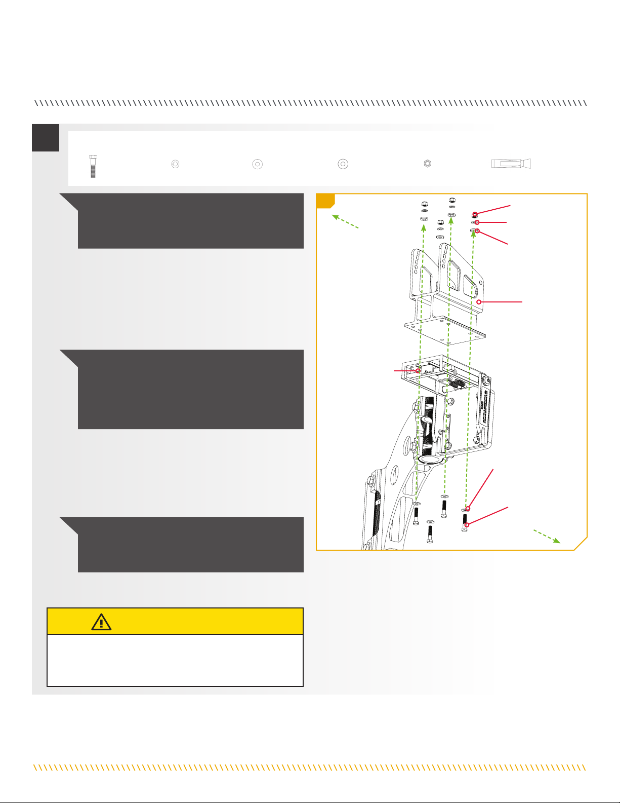
Item /
Assembly Part # Description Qty.
A✖TALON TILT BRACKET 1
B
Includes
2-12
2994910 BAG ASSY, TALON TILT BRACKET 1
2 2373521 BOLT-5/16-18 X 1 1/2" HHCS SS 8
4 2223100 NUT-5/16-18 NYLOCK S/S 8
6 2371756 WASHER-LOCK, 5/16" 8
8 2261722 WASHER-FLAT 5/16 S/S 8
10 2371746 WASHER .750 X .3125 SS *THICK* 8
12 2378608 ANTI SEIZE TUBE, 4CC, TALON 1
14 2374976 sINSTR.SHEET,TILT BRKT 8'10'12' 1
C2992345 CRUTCH/PIVOT ASM, TILT BRACKET 1
D2992345 DECK SUPPORT PIVOT & LEG W/ LEG TIP SUPPORT 1
E✖LEG TIP SUPPORT 1
TOOLS AND RESOURCES REQUIRED
MOUNTING CONSIDERATIONS
✖This part is included in an assembly and cannot be ordered individually.
sNot shown on Parts Diagram.
WARNING
The Talon Tilt Bracket is not designed to be used in the tilted (down) position while trailering, or while under way on the water. Any
attempt to use this product in such a fashion could result in property damage or personal injury, and will void the warranty. Johnson
Outdoors will not be held responsible for such damage or injury resulting from misuse of this product.
minnkotamotors.com | 5
©2019 Johnson Outdoors Marine Electronics, Inc.
INSTALLATION

Mounting the Tilt Bracket
a. Disconnect the Talon from power before beginning
the installation.
1
1b1a
NOTICE: It may be necessary to have a second person
help with this installation.
INSTALLATION
WARNING
To avoid electric shock or unexpected Talon operation, make
sure the Talon is not connected to a power source.
b. Remove the Talon from the Talon Mounting Bracket
by loosening the 4 Nylock Nuts that hold the Talon
in place. Do not remove the nuts, only loosen them.
It may be necessary to have a second person holding
the Talon while the Nylock Nuts are being loosened.
c. Lift the Talon out of the Mounting Bracket and set
it aside.
Talon
Talon
Mounting
Bracket
Talon
Power
Cables
Nylock
Nut
Inboard
Outboard
WARNING
Your Talon MUST be kept in the upright and locked position while trailering, and while under main engine power at anything higher
than idle speeds.
2. The Talon Tilt Bracket can only be installed with the use of a Talon Adapter Bracket (Pontoon Bracket 1810225, Jack Plate 1810340
or sandwich style Adapter Brackets 1810302 for Port or 1810303 for Starboard) to ensure proper clearances at the pivot point. Direct
transom mount applications will not have proper clearance.
Tilted (Down) Position Tilted (Up) Position
Complete Typical Installation
6 | minnkotamotors.com ©2019 Johnson Outdoors Marine Electronics, Inc.
INSTALLATION

2ITEM(S) NEEDED
#A x 1
d. If the Mounting Bracket is already mounted to an
adapter bracket, remove the Mounting Bracket from
it. Any hardware that was holding the Mounting
Bracket to an adapter bracket should be discarded.
Do not reuse the old hardware.
e. Take the Tilt Bracket (Assembly #A) and align it
with the Mounting Holes on the Flag Mounting
Plate Bracket. The Tilt Bracket should be oriented
so that the Latch Lever is positioned upward and
facing inboard.
2e
Outboard
Tilt
Bracket
Flag Mounting
Plate Bracket
Latch Lever
Mounting
Holes
Mounting
Holes
Mounting
Holes Mounting
Holes
Inboard
3ITEM(S) NEEDED
#2 x 4 #6 x 4 #8 x 4 #10 x 4 #4 x 4 #12 x 1
f. Push in the Latch Lever to open the Tilt Bracket.
Take four 5/16-18 Hex Head Cap Crews (Item #2)
and place one 5/16” Flat Washer (Item #8) on
each. With the Tilt Bracket in the open position and
aligned with the Flag Mounting Plate Bracket, put
one Bolt in each of the four Mounting Holes to join
the two pieces.
NOTICE: To prevent seizing of the stainless steel
hardware, do not use high speed installation tools.
Applying an anti-seize will help prevent seizing.
CAUTION
Watch for pinch points between the Talon Tilt Bracket and
the Tilt Bracket Arm when installing and using the bracket.
g. Take four .750 X .3125 Thick Stainless Steel
Washers (Item #10), four Lock Washers (Item #6)
and four Nylock Nuts (Item #4) and place anti-
sieze (Item #12) on all of the hardware. Place
one Stainless Steel Washer, followed by a locking
washer and Nylock Nut on the end of each bolt.
3g
Hex Head
Cap Crew
Flat Washer
Nylock
Nut
Lock
Washer
Thick
Stainless
Steel Washer
Outboard
Inboard
3f
Mounting
Holes
3f
Tilt
Bracket
Latch
Lever
minnkotamotors.com | 7
©2019 Johnson Outdoors Marine Electronics, Inc.
INSTALLATION
h. With the Tilt Bracket still in the open position, mount
the Mounting Bracket to the Tilt Bracket. Take four
5/16-18 Hex Head Cap Crews (Item # 2) and place
one 5/16” Flat Washer (Item #8) on each. With the
Tilt Bracket in the open position and aligned with the
Mounting Bracket, put one Bolt in each of the four
Mounting Holes to join the two pieces.
i. Take four .750 X .3125 Thick Stainless Steel
Washers (Item #10), four Lock Washers (Item #6)
and four Nylock Nuts (Item #4) and place anti-
sieze (Item #12) on all of the hardware. Place one
Stainless Steel Washer, followed by a locking washer
and Nylock Nut on the end of each bolt.
4
4h
ITEM(S) NEEDED
#2 x 4 #6 x 4 #8 x 4 #10 x 4 #4 x 4 #12 x 1
NOTICE: To prevent seizing of the stainless steel
hardware, do not use high speed installation tools.
Applying an anti-seize will help prevent seizing.
NOTICE: It will be necessary to have a second
person hold the Tilt Bracket open during this step
of the installation.
NOTICE: Take note of the orientation of the
mounting hardware. The heads of the bolts must
be installed to the inside of the Tilt Bracket. The
Stainless Steel Washers provided must be used on
the outside of the Tilt Bracket.
j. Verify that all mounting hardware is tightened to 30
ft-lbs and secure.
Tilt Bracket
Hex Head
Cap Crew
Flat Washer
Mounting
Bracket
Outboard
Inboard
Nylock Nut
Lock Washer
Thick Stainless
Steel Washer
CAUTION
Periodically check that all 8 sets of bolts installed are at
the recommended torque of 30 ft-lbs to ensure proper
operation and tight hardware.
8 | minnkotamotors.com ©2019 Johnson Outdoors Marine Electronics, Inc.
INSTALLATION

5
Assembly
Track
Talon
Assembly
Track
Assembly
Track
Assembly
Track
Talon
Talon
Vertical
Stop Bolt
Mounting
Straps
Mounting
Bracket
Mounting
Bracket
Mounting
Strap
5l
k. Next the Talon should be installed on the Mounting
Bracket. Press the Latch Lever on the Tilt Bracket
to return it to the closed position.
5m
5m
NOTICE: We recommend a second person to help
with this step of the installation.
NOTICE: If the Talon was previously installed, the
Water Deflection Shield may need to be removed
and reinstalled after the Talon is secure. Refer to the
Talon Owners Manual on how to install the shield.
n. While supporting the Talon, adjust it and the
Vertical Stop Bolt up or down in the Mounting
Bracket so that the bottom of the Talon is not less
than 4 inches above the Bottom of the hull of the
boat, or the waterline of the boat. Once in place,
temporarily tighten the Vertical Stop Bolt.
o. Double check the placement of the Talon and make
sure it meets all of the mounting considerations.
Make any adjustments as necessary. When the
position of the Talon is acceptable, secure the four
Hex Head Cap Screws and Nylock Nuts holding the
Mounting Straps in place with a 9/16" Box End or
Socket Wrench. Use a torque wrench to tighten to a
recommended torque of 20 to 30 ft-lbs. Tighten the
Vertical Stop Bolt.
6
4" Minimum
Hull
Vertical
Stop Bolt
Hex Head
Cap
Screws
Mounting
Bracket
Talon
Assembly
Hull directly
below Talon
Bottom Edge
of Talon
NOTICE: Additional adjustments may need to be
made to the mount after a trial run with the boat on
the water. Periodically re-tighten the four nuts and
screws to 20 to 30 ft-lbs.
CAUTION
Check tension of the 4 vertical adjustment nuts after initial
use and periodically thereafter to ensure they are at the
recommended torque of 20 to 30 ft-lbs.
l. Take the Talon and notice that there is an Assembly
Track located on both sides of the Talon.
m. Carefully lift the Talon into the Mounting Bracket
and align the Mounting Straps with the Assembly
Track. Slide the Guard Washers to the inside wall
of the Mounting Bracket, so that they sit between it
and the Talon Assembly. Slide the Talon down the
Assembly Tracks until it comes in contact with the
Vertical Stop Bolt.
minnkotamotors.com | 9
©2019 Johnson Outdoors Marine Electronics, Inc.
INSTALLATION
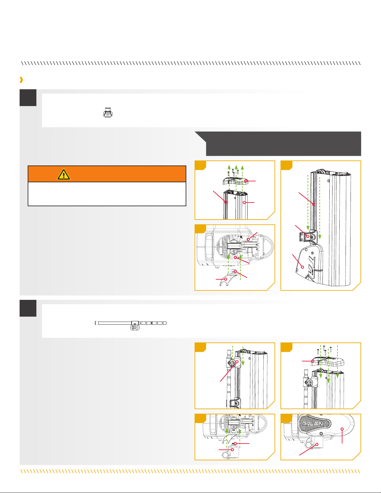
Installing the Adjustable Deck Support
a. With the power still disconnected from the Talon,
remove the top cover from the Talon using a #2
Phillips screw driver. There are a total of 2 or 4
screws holding the cover in place.
1
1a
1b
1c
WARNING
To avoid electric shock or unexpected Talon operation, make
sure the Talon is not connected to a power source.
b. Install the Leg Tip Support (Assembly #E) on the
Port (left) side of the Talon. Do this by loosening the
Square Nut until it is flush with the end of the screw.
c. Slide the support into the Assembly Track making
sure the Washer is on the outside of the track and
the Square Nut is on the inside of the track.
d. Position the Leg Tip Support against the top edge
of the Talon Motor Cover for the moment. The final
position of this support will be determined later.
NOTICE: Take care not to damage wires on the Talon
Cover for Talons that are equipped with a Work Light.
ITEM(S) NEEDED
#E x 1
2
2e 2f
2e 2f
ITEM(S) NEEDED
e. Take the Deck Support Pivot (Assembly #D) and
install it by loosening the Square Nut until it is
flush with the end of the Shoulder Bolt Threads.
Slide the support into the Assembly Track of the
Talon. Make sure the washer is on the outside of
the Talon and the Square Nut is on the inside of the
track. The installed Deck Support Pivot will already
have the Support Leg installed. Do not completely
tighten any of the fasteners at this time.
f. Reinstall the Talon cover that was removed. Tighten
all four screws securely.
Deck
Support
Pivot
Assembly
Track
Talon
Cover
Talon
Square
Nut
Assembly
Track
Leg Tip
Support
Talon
Assembly
Track
Leg Tip
Support
Talon
Motor
Cover
#D x 1
Talon
Cover
Talon
Cover
Deck
Support
Pivot
Deck
Support
Pivot
Square
Nut
10 | minnkotamotors.com ©2019 Johnson Outdoors Marine Electronics, Inc.
INSTALLATION

3
4
3g
4j
g. Loosen the Support Leg Locking Screw until the
Support Leg moves freely.
h. In order to determine the best position for the
Support Leg, release the Talon Tilt Bracket by
pressing on the Locking Lever. With the Talon
supported, lower the Talon in the Tilt Bracket.
Support
Leg
Locking
Screw
Support
Leg
CAUTION
While performing work on the Talon or boat, make sure the
weight of the Talon is supported when the Tilt Bracket is
engaged to Tilt the Talon. If the Talon is not supported, the
Talon can fall and cause injury to people or property. Avoid
the risk of injury by supporting the weight of the Talon.
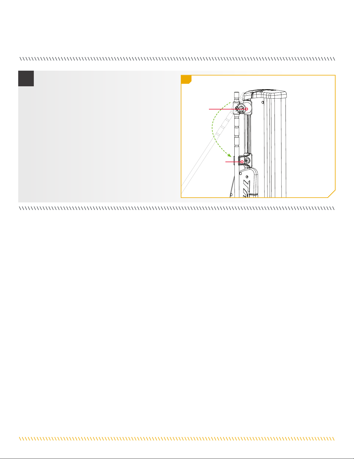
i. Pull out on the Deck Support Pivot and rotate it 90
degrees. The pivot will lock into its “in use” position.
j. Position the Support Leg Pivot along the length of
Talon between the Talon top cover and the Talon
Motor in the best location for your boat. Tighten the
Support Leg Pivot into place using the ¼” Allen
wrench.
k. Adjust the Leg length to one of the machined slot
locations that works best and retighten the Locking
Screw that was loosened previously.
l. Adjust the Leg Tip Support position according to
the adjusted Support Leg length, so that the end of
the Leg will rest in the Cradle. Tighten the Leg Tip
Support using a 7/32” Allen Wrench.
3h
3i
Deck
Support
Pivot
Support
Leg
Top Cover
Support
Leg
Support
Leg Pivot
Leg Tip
Support
Talon Motor
minnkotamotors.com | 11
©2019 Johnson Outdoors Marine Electronics, Inc.
INSTALLATION
55n
m. Tilt the Talon up to normal operating position and
verify that the Tilt Bracket locks.
n. Next, pull out and pivot the Deck Support back to
its stowed position into the Leg Tip Support.
o. After final adjustments to the length of the support
leg, any extra length can be cut off just above the
deck support pivot using a standard hand saw.
Deck
Support
Leg Tip
Support
12 | minnkotamotors.com ©2019 Johnson Outdoors Marine Electronics, Inc.
INSTALLATION

ENVIRONMENTAL COMPLIANCE STATEMENT
It is the intention of JOME to be a responsible corporate citizen, operating in compliance with known and applicable environmental
regulations, and a good neighbor in the communities where we make or sell our products.
WEEE DIRECTIVE
EU Directive 2002/96/EC “Waste of Electrical and Electronic Equipment Directive (WEEE)” impacts most distributors, sellers, and
manufacturers of consumer electronics in the European Union. The WEEE Directive requires the producer of consumer electronics to
take responsibility for the management of waste from their products to achieve environmentally responsible disposal during the product
life cycle.
WEEE compliance may not be required in your location for electrical & electronic equipment (EEE), nor may it be required for EEE
designed and intended as fixed or temporary installation in transportation vehicles such as automobiles, aircraft, and boats. In some
European Union member states, these vehicles are considered outside of the scope of the Directive, and EEE for those
applications can be considered excluded from the WEEE Directive requirement.
This symbol (WEEE wheelie bin) on product indicates the product must not be disposed of with other household
refuse. It must be disposed of and collected for recycling and recovery of waste EEE. Johnson Outdoors Inc. will mark
all EEE products in accordance with the WEEE Directive. It is our goal to comply in the collection, treatment, recovery,
and environmentally sound disposal of those products; however, these requirements do vary within European Union
member states. For more information about where you should dispose of your waste equipment for recycling and
recovery and/or your European Union member state requirements, please contact your dealer or distributor from which
your product was purchased.
DISPOSAL
Minn Kota Talons are not subject to the disposal regulations EAG-VO (electric devices directive) that implements the WEEE directive.
Nevertheless never dispose of your Minn Kota Talon in a garbage bin but at the proper place of collection of your local town council.
Never dispose of battery in a garbage bin. Comply with the disposal directions of the manufacturer or his representative and dispose of
them at the proper place of collection of your local town council.
minnkotamotors.com | 13
©2019 Johnson Outdoors Marine Electronics, Inc.
COmpLIANCE STATEmENTS
TROUBLESHOOTING AND REPAIR
We offer several options to help you troubleshoot and/or repair your product. Please read through the options listed below.
Buy Parts Online
You can buy parts on-line directly from our website at minnkotamotors.com. Orders confirmed by 12 Noon Central Time, with
Overnight Shipping selected, should ship the same business day if the parts are in stock. All other orders should ship within the
next 3 business days, depending on the shipment method chosen, and if the parts are in stock.
Frequently Asked Questions
We have FAQs available on our website to help answer all of your Minn Kota questions. Visit minnkotamotors.com and click on
“Frequently Asked Questions” to find an answer to your question.
Call Us (for U.S. and Canada)
Our consumer service representatives are available Monday – Friday between 7:00 a.m. – 4:30 p.m. CST at 800-227-6433. If you
are calling to order parts, please have the 11-character serial number from your product, specific part numbers, and credit card
information available. This will help expedite your call and allow us to provide you with the best consumer service possible. You can
reference the parts list located in your manual to identify the specific part numbers.
Email Us
You can email our consumer service department with questions regarding your Minn Kota products. To email your question, visit
minnkotamotors.com and click on “Support”.
Authorized Service Centers
Minn Kota has over 800 authorized service providers in the United States and Canada where you can
purchase parts or get your products repaired. Please visit our Authorized Service Center page on our
website to locate a service provider in your area.
Scan to visit Minn
Kota service online.
14 | minnkotamotors.com ©2019 Johnson Outdoors Marine Electronics, Inc.
TROUbLEShOOTINg AND REpAIR

B
E
F
D
C
A
6
4
4
26
6
24
10
8
7
14
15
12
23
25
27
28
29
1
13
3
16
12
11
15
14
12
30
31
22
21
20
19
18
17
5
6
12
32
34 33
35
36
TALON TILT BRACKET
This page provides Minn Kota® WEEE compliance disassembly instructions. For more information about where you should dispose of
your waste equipment for recycling and recovery and/or your European Union member state requirements, please contact your dealer
or distributor from which your product was purchased. Tools required, but not limited to: flat head screw driver, Phillips screw driver,
socket set, pliers, wire cutters.
Talon Tilt Bracket Parts Diagram
minnkotamotors.com | 15
©2019 Johnson Outdoors Marine Electronics, Inc.
pARTS DIAgRAm & pARTS LIST

Assembly Part # Description Qty.
A✖TALON TILT BRACKET 1
B 2994910 BAG ASSY, TALON TILT BRACKET 1
C 2770237 TALON TILT BRACKET & BAG ASSY 1
D 2992345 DECK SUPPORT PIVOT & LEG W/ TIP SUPPORT 1
E✖CRUTCH/PIVOT ASM, TILT BRACKET 1
F 2992341 CRUTCH, TILT BRACKET ASSEMBLY 1
Item Part # Description Qty
1 2371941 BASE-TILT, MACHINED 1
2 2375119 PAD-WEAR, LEFT,TALON TILT BRKT 1
3 2375114 PAD-WEAR,RIGHT,TALON TILT BRKT 1
4 2378601 RIVET-POP, 1/8", 316 SS 6
5 2370237 COVER-TILT, MACHINED 1
6 2376730 PLUG-SPACER,TALON TILT BRK 2
7 2377218 LEVER-TILT, MACHINED 1
8 2375417 INSULATOR, TILT BRACKET 1
9 2372671 PIN-LATCH, TILT BRACKET 1
10 2372654 PIN-SPRING 1/8"X 1 1/4" SS 1
11 2372667 PIN-PIVET, 2-GROOVE, SS 1
12 2370007 BEARING-SLEEVE, .625 X .375 4
13 2372744 SPRING, LATCH, TILT BRACKET 2
14 2383443 SCREW-3/8-16 BHCS, SS 2
15 2371759 WASHER-3/8 HD FENDER SS 2
16 2375769 LABEL-WARNING,TILT BRACKET 1
17 2373521 BOLT-5/16-18 X 1 1/2" HHCS SS 8
18 2371756 WASHER-LOCK, 5/16" 8
19 2261722 WASHER-FLAT 5/16 S/S 8
20 2223100 NUT-5/16-18 NYLOCK S/S 8
21 2371746 WASHER .750 X .3125 SS 8
22 2378608 ANTI SEIZE TUBE, 4CC, TALON 1
23 2373131 NUT-SQUARE 3/8-18 SS 1
24 2371758 WASHER-3/8 HD FLAT SS 1
25 2372355 CRUTCH, INNER PIVOT (2992345) 1
26 2372346 CRUTCH, OUTER PIVOT, MACH 1
27 2073408 SCREW-1/4-20 X 7/8 PPH S/S 1
28 2372747 SPRING, TALON STABILIZER 1
29 2373531 BOLT-SHOULDER,TALON STABILIZER 1
Talon Tilt Bracket Parts List
✖This part is included in an assembly and cannot be ordered individually.
sNot shown on Parts Diagram.
16 | minnkotamotors.com ©2019 Johnson Outdoors Marine Electronics, Inc.
PARTS DIAGRAM & PARTS LIST

Item Part # Description Qty
30 ✖CRUTCH, TILT BRACKET ASSEMBLY 1
31 2265100 BUMPER 1
32 2371758 WASHER-3/8 HD FLAT SS 1
33 2373131 NUT-SQUARE 3/8-18 SS 1
34 2372360 CRUTCH,SUPPORT,INJ.MOLDED(N/A) 1
35 2091701 WASHER-PROP (LARGE) MAX101 1
36 2383443 SCREW-3/8-16 BHCS, SS 4
s2374976 INSTR.SHEET,TILT BRKT 8'10'12' 1
✖This part is included in an assembly and cannot be ordered individually.
sNot shown on Parts Diagram.
minnkotamotors.com | 17
©2019 Johnson Outdoors Marine Electronics, Inc.
PARTS DIAGRAM & PARTS LIST
Minn Kota Consumer & Technical Service
Johnson Outdoors Marine Electronics, Inc.
PO Box 8129
Mankato, MN 56001
121 Power Drive
Mankato, MN 56001
Phone (800) 227-6433
Fax (800) 527-4464
minnkotamotors.com
©2019 Johnson Outdoors Marine Electronics, Inc.
All rights reserved.
Part #2374976 ECN 40106 Rev G 09/19
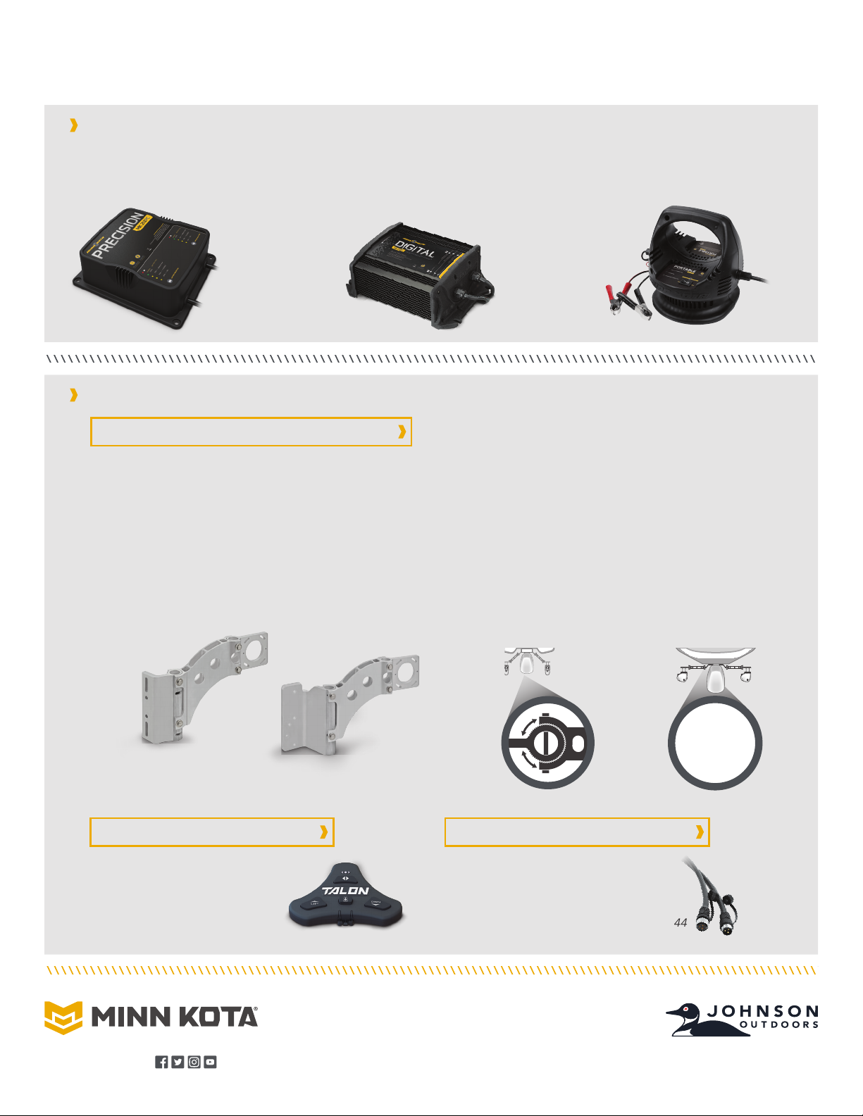
ON-BOARD & PORTABLE BATTERY CHARGERS
Stop buying new batteries and start taking care of the ones you’ve got. An inaccurate charger can actually damage your battery
over time – creating shorter run times and shorter overall life. Digitally controlled Minn Kota chargers are designed to provide a
fast and precise charge that protect and extend battery life.
TALON ACCESSORIES
MK210D M K110 P DMK212PC
RECOmmENDED ACCESSORIES
Unparalleled Strength
We built Talon with uncompromising power. And we built the
brackets the exact same way. Made with extruded aluminum and
reinforced with rugged construction, our brackets hold Talon steady
whether you’re trailering or tearing through heavy chop.
1810244
1810257
It’s easy to choose your bracket, easy to install it and pretty much impossible for anything to stop it. Talon’s Universal
Modular Adapter Brackets are built stronger than they have to be, and their innovative modular design lets you put
Talon in just the right position on your boat.
Universal Modular Design
Two brackets. Any transom. The universal design fits any situation, and the
brackets can be adjusted and tweaked to the perfect orientation. Two pivot
points let you adjust Talon to the perfect orientation (based on your transom
style, outboard location and other factors). Once it’s in position, interlocking
teeth clamp down to lock it into place.
Jack Plate
Adapter Bracket
Sandwich-Style
Adapter Bracket
1810340
UNIVERSAL MODULAR ADAPTER BRACKETS
QUICK RELEASE DISCONNECT PLUG
TALON WIRELESS FOOT SWITCH
1810303
Control Talon from the bow, with full
command of stow, deploy, anchoring
modes and work light.
This heavy-duty, waterproof
connector features an all-inclusive
screw-lock design.

SUPPORT INCLINABLE
Manuel du propriétaire
Compatible avec les modèles d’ancres Talon pour eaux peu profondes.

EXAMPLE
Modèle : _______________________________________________________________________________________________________________
Numéro de série : ________________________________________________________________________________________________________
Date de l’achat : _________________________________________________________________________________________________________
Magasin où l’achat a été effectué : _________________________________________________________________________________________
ENREGISTREMENT
N’oubliez pas de conserver votre reçu et d’enregistrer
immédiatement votre Talon. Pour bénéficier de tous les avantages
de la garantie de votre produit, veuillez remplir et envoyer la carte
d’enregistrement par la poste; vous pouvez aussi enregistrer votre
produit en ligne à minnkotamotors.com.
NUMÉRO DE SÉRIE
Le numéro de série à 11 caractères Minn Kota est très
important. Cela permet de déterminer le modèle spécifique et
l’année de fabrication. Lorsque vous contactez le service à la
clientèle ou que vous enregistrez votre article, vous aurez besoin
du numéro de série de votre article. Nous vous suggérons
d’écrire le numéro de série afin qu’il soit disponible à des fins
de référence future.
INFORMATIONS SUR LE TALON (à des fins de référence par le client seulement)
AVIS : Le numéro de série sur votre support inclinable est
inscrit à l’intérieur du support, près de la tige de verrouillage.
Made by Minn Kota
Johnson Outdoors
Marine Electronics, Inc.
121 Power Drive
Mankato, MN 56001 USA
Trolling Motors
Produced in 2012
Talon Tilt Bracket
MODEL 1810222
SER NO M365 MK12345
EXEMPLE
MERCI
Votre support inclinable Talon est conçu pour permettre une inclinaison aisée lorsque nécessaire. Cela peut subvenir lorsqu’on
rencontre des obstacles suspendus à faible hauteur ou lorsqu’on doit reculer ou avancer sous des zones à faible hauteur libre. La
fonction d’inclinaison peut aussi servir à prolonger votre Talon pour faciliter les besoins de nettoyage.
20 | minnkotamotors.com ©2019 Johnson Outdoors Marine Electronics, Inc.
INTRODUCTION
Other manuals for TALON
7
Table of contents
Languages:
Other MINN KOTA TV Mount manuals

MINN KOTA
MINN KOTA MKA-57 User manual

MINN KOTA
MINN KOTA MKA-23 User manual

MINN KOTA
MINN KOTA MKA-53 User manual

MINN KOTA
MINN KOTA Raptor Port 1810361 User manual

MINN KOTA
MINN KOTA MKA-16-03 User manual

MINN KOTA
MINN KOTA MKA-61 User manual

MINN KOTA
MINN KOTA 1810220 User manual

MINN KOTA
MINN KOTA MKA-16-03 User manual

MINN KOTA
MINN KOTA MKA-48 User manual

MINN KOTA
MINN KOTA MKA-51 User manual


