MINN KOTA MKA-61 User manual

MKA-61 OR MKA-62 CABLE STEER
QUICK RELEASE BRACKET
1862042 & 1862052
Compatible with most Minn Kota
®
cable steer and hand control models including QUEST series motors.
pNot shown on Parts Diagram.
✖This part is included in an assembly and cannot be ordered individually.
TOOLS AND RESOURCES REQUIRED
• Drill
• ⁄” Drill Bit
• ⁄” Drill Bit
• ⁄” Allen Wrench
• #3 Phillips Screwdriver
• Awl, pencil or similar marking tool
• A second person to help with
the installation
• #4 Phillips Screwdriver
• ⁄” Box End or Open End Wrench
• ⁄” Box End or Open End Wrench
88
1010
1818
1212
2626
2222 2424
2020
2828
1616
1414
22
AA
BB
CC
44
Item /
Assembly Part # Description Qty.
A
Items 2 - 10
2990103 QUICK RELEASE MNT LONG ASM 1
2990102 QUICK RELEASE MNT SHORT ASM 1
2
2371650 PLATE-TOP, ANODIZED, LONG 1
2371660 PLATE-TOP, ANODIZED, SHORT 1
4
2371655 PLATE-BTM, ANODIZED, LONG 1
2371665 PLATE-BTM, ANODIZED, SHORT 1
6✖ 2372625 PIN-SPRING,SLOTTED 5/16 X 3/4 1
8 2373145 NUT-JAM, 1/4, SS 2
10 2373560 SCREW-1/4-20 X 1.50 SHCS SS 2
B
Items 12 - 18 2994829 BAG ASSY-MAX QUICK RELEASE 1
12 2500000 SCREW-1/4-20 X 2 1/4 PPH S/S 12
14 2073408 SCREW-1/4-20 X 7/8 PPH S/S 6
16 2261713 WASHER-1/4 FLAT 18-8 SS 6
18 2263103 NUT-1/4-20 NYLOCK SS 12
C
Items 20 - 26 2994952 BAG ASM, 5/16" HDW,CBL STR QRB 1
20 2223100 NUT-5/16-18 NYLOCK S/S 12
22 2293406 SCREW-5/16-18 X 2.25" PPH SS 6
24 2293407 SCREW-5/16-18X 3/4"PPH SS 6
26 2291701 WASHER-5/16 X 1.5 FLAT SS 6
28 2378608 ANTI SEIZE TUBE, 4CC, TALON 1
p30 2377181 INSTR. SHEET, CBL STEER QRB 1
WARNING
Avoid the risk of electric shock or unexpected motor operation. Always ensure the Power Cables of the trolling motor being installed to
the Quick Release Bracket are not connected to a power source before beginning installation. Place the trolling motor on a level surface
to prevent it from falling.
1010
88
66
1 | minnkota.johnsonoutdoors.com ©2023 Johnson Outdoors Marine Electronics, Inc.

UltrexTM and Fortrex®Ultrex QUESTTM Maxxum® Edge
InboardInboard InboardInboard InboardInboard
The MKA-61 and MKA-62 are designed to allow the trolling motor to be quickly removed from and reattached to the boat deck. The
top and bottom plates for the Quick Release Brackets slide together and are tightened and secured to one another using dual locking
hardware. The MKA-61 and MKA-62 are compatible with the Ultrex, Fortrex, Maxxum, and Edge Minn Kota® trolling motors and are
recommended for the higher thrust associated with the Ultrex QUEST series motors. The MKA-61 fits 45” shaft and smaller foot-control
motors and 52” shaft and smaller hand-control motors. The MKA-62 fits 52” to 72” shaft, foot-control motors, and 62” shaft, hand-
control motors. The base extrusion or mounting bracket of the trolling motors may vary. Please note the appearance of the applicable
trolling motors and mounting brackets. For a complete list of motors compatible with the MKA-61 and MKA-62, please refer to the
website at minnkota.johnsonoutdoors.com.
InboardInboard
NOTICE: Images are a graphical representation and may
vary from your motor.
MOUNTING CONSIDERATIONS
WARNING
For motors with Lift-Assist (Fortrex, Ultrex, and Ultrex QUEST),
the Lift Cylinder or Gas Spring(s) should be disengaged until
installation is complete to prevent injury. Refer to the trolling
motor Owner’s Manual for instructions to disengage the Lift
Cylinder or Gas Spring(s).
NOTICE: For motors with Lift-Assist (Fortrex, Ultrex, and Ultrex QUEST), the Lift Cylinder or Gas Spring(s) should be disengaged
until installation is complete to prevent injury. If present, Minn Kota also recommends removing the Steering Module or BowGuard,
for ease of installation. For Fortrex trolling motors, please review the “Disconnect the Gas Spring Pin” section of the Fortrex Owner’s
Manual (#2287106) and then “Remove the Bowguard from the Mount.” For Ultrex trolling motors, please review the “Removal of
the Steering Module” section of the Ultrex Owner’s Manual (#2297162) to first “Disconnect the Gas Spring” and then “Remove the
Motor from Mount.” For Ultrex QUEST trolling motors, please review the “Removal of the Steering Module” section of the Ultrex
QUEST Owner’s Manual (#2297166) to first “Disconnect the Gas Springs” and then “Remove Motor from Mount.” Find Owner’s
Manuals online at minnkota.johnsonoutdoors.com.
Complete Typical Installation
It is recommended that the motor be mounted as close to the keel
or centerline of the boat as possible. Ensure the area under the
mounting location is flat, is clear to drill holes, and install nuts
and washers. Make sure the motor rest is positioned far enough
beyond the edge of the boat. The motor must not encounter
obstructions as it is lowered into the water or raised into the boat
when stowed and deployed.
2 | minnkota.johnsonoutdoors.com ©2023 Johnson Outdoors Marine Electronics, Inc.

INSTALLATION
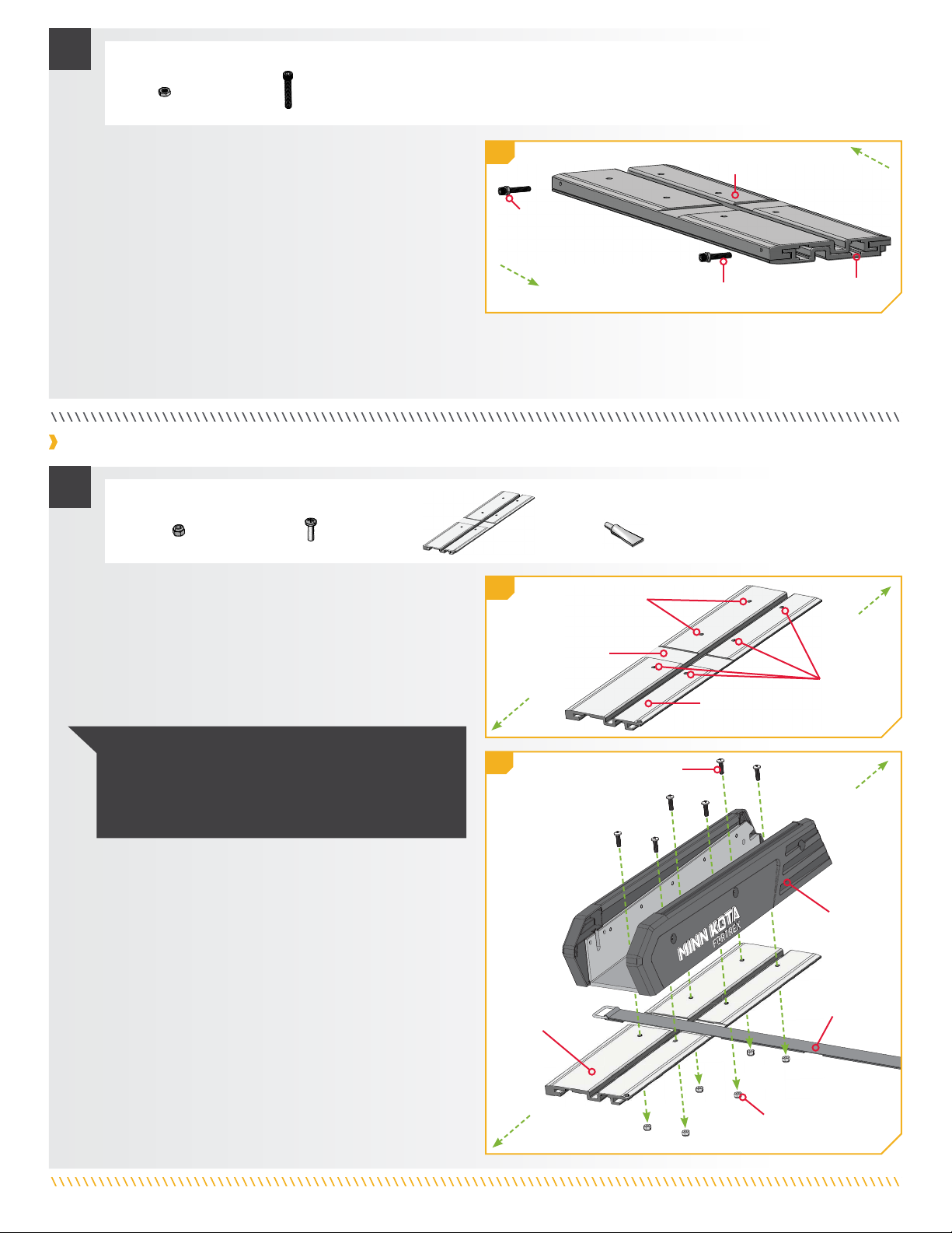
Separate the Quick Release Bracket Plates
a. Place the Quick Release Bracket (Assembly #A) on
a level surface with the recess for the Hold-Down
Strap facing upwards.
b. Locate the two ¼-20 x 1.50-inch Socket Head Cap
Screws along the side of the plates. Each Socket
Head Cap Screw holds a Jam Nut. Using a ⁄” Allen
Wrench, loosen and remove the two Screws
in a counter-clockwise direction. Keep the Jam
Nuts in place.
c. Set the two ¼-20 x 1.50-inch Socket Head Cap
Screws aside for reassembly later and separate the
Top Plate from the Bottom Plate by lifting the Top
Plate directly up. Notice the location of the Spring
Pin on the Bottom Plate. Later, when the plates are
installed to each other, the Spring Pin should
be placed Outboard.
ITEM(S) NEEDED
1
#A x 1
The top and bottom plates of the MKA-61 and MKA-62 Quick Release Brackets come from the factory secured together. Separate the
plates of the Quick Release Bracket to facilitate installation.
1a
1b
1c
Quick Release BracketQuick Release Bracket
Quick Release BracketQuick Release Bracket
Top PlateTop Plate
Bottom PlateBottom Plate
SpringSpring
PinPin
Socket HeadSocket Head
Cap ScrewCap Screw
Socket Head Cap ScrewSocket Head Cap Screw
Jam NutJam Nut
Jam NutJam Nut
Hold-DownHold-Down
Strap RecessStrap Recess
InboardInboard
OutboardOutboard
NOTICE: The trolling motor and Quick Release Bracket
are heavy. Minn Kota recommends having a second
person help with the installation.
NOTICE: For motors with Lift-Assist (Fortrex, Ultrex, and
Ultrex QUEST), the Lift Cylinder or Gas Spring(s) should be
disengaged until installation is complete to prevent injury.
Minn Kota also recommends removing the Steering Module
or BowGuard if present, for ease of installation.
3 | minnkota.johnsonoutdoors.com ©2023 Johnson Outdoors Marine Electronics, Inc.

Installing the Top Plate to a Maxxum Trolling Motor
a. Take the Top Plate (Item #2) and align the Mounting
Holes on the plate with the Mounting Holes on the
trolling motor Mount. The Mounting Holes closest
to the short edge of the Top Plate should face
Outboard. The Mounting Holes furthest from the
short edge on the Top Plate are the closest to the
Hold-Down Strap Recess and should face Inboard.
MotorMotor
MountMount
Phillips PanPhillips Pan
Head ScrewHead Screw
InboardInboard OutboardOutboard
TopTop
PlatePlate
Nylock NutNylock Nut
NOTICE: Place the Hold-Down Strap (if included with
your motor) between the motor Mount and the Top Plate.
For full function, install the Hold-Down Strap between
the middle pair and most-inboard pair of Mounting Holes
in the Hold-Down Strap Recess.
ITEM(S) NEEDED
1
#12 x 6 #28 x 1
#18 x 6
b. Test the placement of the Hold-Down Strap to be
sure it can hold the Mount as placed. The position of
the buckle on the Hold-Down Strap, either inboard
or outboard, is based on personal preference. The
hook and loop should face downward for the Hold-
Down Strap to function correctly. Take six ¼-20 X
2¼” Phillips Pan Head Screws (Item #12) and six
Nylock Nuts (Item #18). Apply anti-seize (Item #28)
to all hardware. Install the Screws so that they pass
through the Mount and then the Top Plate. Secure
each Screw below the Top Plate with a Nylock Nut.
Hold each Nylock Nut with a ⁄” Open End or Box
End Wrench and tighten each Screw using a #3
Screwdriver to fasten the Mount to the Top Plate.
Make sure all hardware is secure.
Hold-DownHold-Down
StrapStrap
1b
1a
InboardInboard
OutboardOutboard
Hold-DownHold-Down
Strap RecessStrap Recess
MountingMounting
HolesHoles
MountingMounting
HolesHoles
#2 x 1
Top PlateTop Plate
ITEM(S) NEEDED
2
c. Take the Bottom Plate (Item #4) and set it on a level
surface. The Bottom Plate should sit so that the
Spring Pin faces upward. The Spring Pin is present
along the edge of the Bottom Plate that points
Outboard. Take the Top Plate with the trolling motor
installed and place it on the Bottom Plate. Place the
Top Plate so that the holes for the Padlock Slot on
the Top Plate and Bottom Plate align.
#4 x 1
Top PlateTop Plate
Bottom PlateBottom Plate
Padlock SlotPadlock Slot
PadlockPadlock
SlotSlot
Hold-DownHold-Down
StrapStrap
Spring PinSpring Pin
2c
OutboardOutboard
InboardInboard
4 | minnkota.johnsonoutdoors.com ©2023 Johnson Outdoors Marine Electronics, Inc.

Installing the Top Plate to an Edge, Fortrex or Ultrex Trolling Motor
d. Take the two ⁄-20 X 1.50-inch Socket Head Cap
Screws (Item #10), each with a Jam Nut (Item #8)
in place. Slide both plates to align the holes in the
Top Plate and Bottom Plate. Apply anti-seize to all
hardware. Install each ⁄-20 X 1.50 Socket Head Cap
Screw with the Jam Nut in place into the plates using
a ⁄” Allen Wrench. Tighten the Allen Wrench turning
clockwise until there is no movement between the
plates. Tighten an additional quarter turn past tight.
Once the ⁄-20 X 1.50 Socket Head Cap Screws are
tight, take a ⁄” Open End or Box End Wrench and
tighten the Jam Nut. Make sure all hardware is secure.
Socket Head Cap ScrewSocket Head Cap Screw BottomBottom
PlatePlate
Top PlateTop Plate
Jam NutJam Nut
3d
ITEM(S) NEEDED
3
#8 x 2 #10 x 2
InboardInboard
OutboardOutboard
a. Take the Top Plate (Item #2) and align the Mounting
Holes on the plate with the Mounting Holes on the
trolling motor Mount. The Mounting Holes closest
to the short edge of the Top Plate should face
Outboard. The Mounting Holes furthest from the
short edge on the Top Plate are the closest to the
Hold-Down Strap Recess and should face Inboard.
MountMount
Phillips PanPhillips Pan
Head ScrewHead Screw
InboardInboard
OutboardOutboard
TopTop
PlatePlate
Nylock NutNylock Nut
NOTICE: Place the Hold-Down Strap (if included with
your motor) between the motor Mount and the Top Plate.
For full function, install the Hold-Down Strap between
the middle pair and most-inboard pair of Mounting Holes
in the Hold-Down Strap Recess.
ITEM(S) NEEDED
1
#14 x 6
#18 x 6
b. Test the placement of the Hold-Down Strap to be
sure it can hold the Mount as placed. The position of
the buckle on the Hold-Down Strap, either inboard
or outboard, is based on personal preference. The
hook and loop should face downward for the Hold-
Down Strap to function correctly. Take six ⁄-20
x ⁄” Phillips Pan Head Screws (Item #14) and six
Nylock Nuts (Item #18). Apply anti-seize (Item #28)
to all hardware. Install the Screws so that they pass
through the Mount and then the Top Plate. Secure
each Screw below the Top Plate with a Nylock Nut.
Hold each Nylock Nut with a ⁄” Open End or Box
End Wrench and tighten each Screw using a #3
Screwdriver to fasten the Mount to the Top Plate.
Make sure all hardware is secure.
Hold-DownHold-Down
StrapStrap
1b
1a
InboardInboard
OutboardOutboard
Hold-DownHold-Down
Strap RecessStrap Recess
MountingMounting
HolesHoles
MountingMounting
HolesHoles
#2 x 1
Top PlateTop Plate
#28 x 1
5 | minnkota.johnsonoutdoors.com ©2023 Johnson Outdoors Marine Electronics, Inc.

ITEM(S) NEEDED
2
c. Take the Bottom Plate (Item #4) and set it on a level
surface. The Bottom Plate should sit so that the
Spring Pin faces upward. The Spring Pin is present
along the edge of the Bottom Plate that points
Outboard. Take the Top Plate with the trolling motor
installed and place it on the Bottom Plate. Place the
Top Plate so that the holes for the Padlock Slot on
the Top Plate and Bottom Plate align.
#4 x 1
TopTop
PlatePlate
Bottom PlateBottom Plate
Padlock SlotPadlock Slot
PadlockPadlock
SlotSlot
Hold-DownHold-Down
StrapStrap
Spring PinSpring Pin
2c
OutboardOutboard
InboardInboard
d. Take the two ⁄-20 X 1.50-inch Socket Head Cap
Screws (Item #10), each with a Jam Nut (Item #8)
in place. Slide both plates to align the holes in the
Top Plate and Bottom Plate. Apply anti-seize to all
hardware. Install each ⁄-20 X 1.50 Socket Head Cap
Screw with the Jam Nut in place into the plates using
a ⁄” Allen Wrench. Tighten the Allen Wrench turning
clockwise until there is no movement between the
plates. Tighten an additional quarter turn past tight.
Once the ⁄-20 X 1.50 Socket Head Cap Screws are
tight, take a ⁄” Open End or Box End Wrench and
tighten the Jam Nut. Make sure all hardware
is secure.
Socket Head Cap ScrewSocket Head Cap Screw BottomBottom
PlatePlate
Top PlateTop Plate
Jam NutJam Nut
3d
ITEM(S) NEEDED
3
#8 x 2 #10 x 2
InboardInboard
OutboardOutboard
6 | minnkota.johnsonoutdoors.com ©2023 Johnson Outdoors Marine Electronics, Inc.

a. Take the Top Plate (Item #2) and align the Mounting
Holes on the plate with the Mounting Holes on the
trolling motor Mount. The Mounting Holes closest
to the short edge of the Top Plate should face
Outboard. The Mounting Holes furthest from the
short edge on the Top Plate are the closest to the
Hold-Down Strap Recess and should face Inboard.
MountMount
Phillips PanPhillips Pan
Head ScrewHead Screw
OutboardOutboard
TopTop
PlatePlate
Nylock NutNylock Nut
NOTICE: Place the Hold-Down Strap (if included with
your motor) between the motor Mount and the Top Plate.
For full function, install the Hold-Down Strap between
the middle pair and most-inboard pair of Mounting Holes
in the Hold-Down Strap Recess.
ITEM(S) NEEDED
1
#24 x 6
#20 x 6
b. Test the placement of the Hold-Down Strap to be
sure it can hold the Mount as placed. The position of
the buckle on the Hold-Down Strap, either inboard
or outboard, is based on personal preference. The
hook and loop should face downward for the Hold-
Down Strap to function correctly. Take six ⁄-18
x ⁄” Phillips Pan Head Screws (Item #24) and six
Nylock Nuts (Item #20). Apply anti-seize (Item #28)
to all hardware. Install the Screws so that they pass
through the Mount and then the Top Plate. Secure
each Screw below the Top Plate with a Nylock Nut.
Tighten each Screw using a #4 Screwdriver to fasten
the Mount to the Top Plate. Make sure all hardware
is secure.
Hold-DownHold-Down
StrapStrap
1b
1a
Hold-DownHold-Down
Strap RecessStrap Recess
MountingMounting
HolesHoles
Mounting HolesMounting Holes
Top PlateTop Plate
Installing the Top Plate to an Ultrex QUEST Series Trolling Motor
ITEM(S) NEEDED
2
c. Take the Bottom Plate (Item #4) and set it on a level
surface. The Bottom Plate should sit so that the
Spring Pin faces upward. The Spring Pin is present
along the edge of the Bottom Plate that points
Outboard. Take the Top Plate with the trolling motor
installed and place it on the Bottom Plate. Place the
Top Plate so that the holes for the Padlock Slot on
the Top Plate and Bottom Plate align.
Top PlateTop Plate
Bottom PlateBottom Plate
Padlock SlotPadlock Slot
PadlockPadlock
SlotSlot
Hold-DownHold-Down
StrapStrap
Spring PinSpring Pin
2c
OutboardOutboard
InboardInboard
InboardInboard
InboardInboard
OutboardOutboard
#28 x 1#2 x 1
#4 x 1
7 | minnkota.johnsonoutdoors.com ©2023 Johnson Outdoors Marine Electronics, Inc.

d. Take the two ⁄-20 X 1.50-inch Socket Head Cap
Screws (Item #10), each with a Jam Nut (Item #8)
in place. Slide both plates to align the holes in the
Top Plate and Bottom Plate. Apply anti-seize to all
hardware. Install each ⁄-20 X 1.50 Socket Head Cap
Screw with the Jam Nut in place into the plates using
a ⁄” Allen Wrench. Tighten the Allen Wrench turning
clockwise until there is no movement between the
plates. Tighten an additional quarter turn past tight.
Once the ⁄-20 X 1.50 Socket Head Cap Screws are
tight, take a ⁄” Open End or Box End Wrench and
tighten the Jam Nut. Make sure all hardware
is secure.
Socket Head Cap ScrewSocket Head Cap Screw
BottomBottom
PlatePlate
Top PlateTop Plate
Jam NutJam Nut
3d
ITEM(S) NEEDED
3
#8 x 2 #10 x 2
InboardInboard
OutboardOutboard
Installing the Bottom Plate to the Bow (for all trolling motors)
a. Place the Quick Release Bracket with the motor
attached as close to the center line or Keel of the
boat as possible. Make sure to check the clearance
of the motor and the Quick Release Bracket for
any possible obstructions on the bow of the boat.
The trolling motor may be installed on the Port or
Starboard side of the boat.
b. Ensure that all six Mounting Holes on the Bottom
Plate of the Quick Release Bracket can be used to
install the Bottom Plate to the boat deck. Minn Kota
recommends the use of all six Mounting Holes.
1
NOTICE: Images are for graphical representation only
and may vary from your motor.
Boat DeckBoat Deck
BoatBoat
DeckDeck
Hold-Down StrapHold-Down Strap
Hold-Down StrapHold-Down Strap
KeelKeel
KeelKeel
MountMount
MountMount
Pedal ControlPedal Control
Sleeve AssemblySleeve Assembly
Pedal ControlPedal Control
Sleeve AssemblySleeve Assembly
Port
Starboard
NOTICE: If personal preference is to Mount the motor
on the Starboard side of the boat, please see the "Rotate
the Pedal Control Sleeve Assembly for a Starboard
Mount" in the Owner’s manual after the Mount is
secured to the deck of the boat for all Ultrex and Ultrex
QUEST series trolling motors.
8 | minnkota.johnsonoutdoors.com ©2023 Johnson Outdoors Marine Electronics, Inc.

c. Check the placement of the motor in the deployed
position. With the motor deployed, ensure that the
Steering Module and Shaft are a minimum of 1-1/2”
out past the Gunwale of the boat. When stowed
and deployed, the Lower Unit must not encounter
any obstructions.
2
BottomBottom
PlatePlate
BottomBottom
PlatePlate
BottomBottom
PlatePlate
MountingMounting
HolesHoles
MountingMounting
HolesHoles
3
4
d. Ensure that all six Mounting Holes on the Bottom
Plate of the Quick Release Bracket can be used to
install the Bottom Plate to the boat deck. Minn Kota
recommends the use of all six Mounting Holes. Use
an awl, pencil, or similar marking tool and mark the
edges of the Bottom Plate on the bow of the boat.
e. Locate the two ¼-20 x 1.50-inch Socket Head Cap
Screws along the side of the plates. Each ¼-20
x 1.50 Socket Head Cap Screw holds a Jam Nut.
Using a ⁄” Allen Wrench, loosen and remove the
two Screws in a counter-clockwise direction. Keep
the Jam Nuts in place.
f. Reposition the Bottom Plate on the marked location
on the bow of the boat. Make sure the Padlock Slot
is facing inboard.
PadlockPadlock
SlotSlot
PadlockPadlock
SlotSlot
Padlock SlotPadlock Slot
PadlockPadlock
SlotSlot
InboardInboard
InboardInboard
InboardInboard
InboardInboard
OutboardOutboard
OutboardOutboard
OutboardOutboard
3d
3e
3f
4g
4g
1-1/2"1-1/2"
MinimumMinimum
GunwaleGunwale
ShaftShaft
SteeringSteering
ModuleModule
g. Once the Bottom Plate is in position, locate the
Mounting Holes on the base of the Mount. Minn
Kota requires the use of all six Mounting Holes. Use
an awl, pencil, or similar marking tool and mark the
Boat Deck on all six Mounting Holes. Set the Bottom
Plate aside.
Socket HeadSocket Head
Cap ScrewCap Screw
JamJam
NutNut
KeelKeel
MarkedMarked
LocationsLocations
MountingMounting
HolesHoles
MarkedMarked
LocationLocation
MarkedMarked
LocationLocation
OutboardOutboard
NOTICE: Check that the Motor can properly stow and
deploy at the intended mounting location. The Mount
should latch closed when deployed. If the latch on the
Mount does not engage when deployed, it could indicate
that the Mount is not flat on the Boat Deck. Use rubber
washers to level the Mount on the Boat Deck.
9 | minnkota.johnsonoutdoors.com ©2023 Johnson Outdoors Marine Electronics, Inc.
2c

BottomBottom
PlatePlate
ScrewScrew
Flat WasherFlat Washer
Nylock NutNylock Nut
6k
5
6
#12 x 6 #22 x 6#16 x 6 #26 x 6
#18 x 6 #20 x 6
ITEM(S) NEEDED
BoatBoat
DeckDeck
BottomBottom
PlatePlate
Padlock SlotPadlock Slot
InboardInboard
OutboardOutboard
OutboardOutboard
5j
MountingMounting
Holes &Holes &
DrilledDrilled
LocationsLocations
SpringSpring
PinPin
MarkedMarked
LocationLocation
h. If installing an Edge, Fortrex, Maxxum, or
Ultrex trolling motor, drill through the deck of
the boat using a Drill and a ⁄” Drill Bit on the
marked locations.
i. If installing a QUEST series Ultrex trolling motor,
drill through the deck of the boat using a Drill and a
⁄” Drill Bit on the marked locations.
j. Return the Bottom Plate to the Boat Deck aligning
the Mounting Holes with the Drilled Holes.
#28 x 1
BoatBoat
DeckDeck
InboardInboard
InboardInboard
5h DrilledDrilled
LocationsLocations
OutboardOutboard
k. If installing an Edge, Fortrex, Maxxum or Ultrex
trolling motor, take six ¼-20 x 2¼” Phillips Pan
Head Screws (Item #12), six ¼” Flat Washers
(Item #16), and six ¼-20 Nylock Nuts (Item #18).
Apply anti-seize (Item #28) to all hardware. Insert
each Phillips Pan Head Screw into the Bottom Plate
and through the Boat Deck. Place one Flat Washer
and one Nylock Nut on the end of each Screw below
the Boat Deck. While holding each Nylock Nut with
⁄” Box End or Open End Wrench, use a #3 Phillips
Screwdriver to tighten each Screw. Make sure all
hardware is secure.
l. If installing a QUEST series Ultrex trolling motor,
take six ⁄-18 x 2.25” Phillips Pan Head Screws
(Item #22) and six ⁄” x 1.5” Flat Washers
(Item #26) and six ⁄-18 Nylock Nuts (Item #20).
Apply anti-seize (Item #28) to all hardware. Insert
each Phillips Pan Head Screw into the Bottom Plate
and through the Boat Deck. Place one Flat Washer
and one Nylock Nut on the end of each Screw. While
holding each Nylock Nut with a ⁄” Box End or Open
End Wrench, use a #4 Phillips Screwdriver to tighten
each Screw. Make sure all hardware is secure.
NOTICE: The mounting surface for the Bottom Plate must
be completely flat; otherwise, the Top Plate will not fit
correctly. Rubber washers can be used to shim the Bottom
Plate flat before the hardware is tightened.
10 | minnkota.johnsonoutdoors.com ©2023 Johnson Outdoors Marine Electronics, Inc.

a. Take the Top Plate with the motor attached and
slide it into the Bottom Plate. The Top Plate slides
outboard from the back end of the Bottom Plate.
Once slid all the way outboard, secure the Top Plate
to the Bottom Plate.
b. Take the two ⁄-20 X 1.50-inch Socket Head Cap
Screws (Item #10), each with a Jam Nut (Item #8)
in place. Slide both plates to align the holes in the
Top Plate and Bottom Plate. Apply anti-seize to all
hardware. Install each ⁄-20 X 1.50 Socket Head Cap
Screw with the Jam Nut in place into the plates using
a ⁄” Allen Wrench. Tighten the Allen Wrench turning
clockwise until there is no movement between the
plates. Tighten an additional quarter turn past tight.
Once the ⁄-20 X 1.50 Socket Head Cap Screws are
tight, take a ⁄” Open End or Box End Wrench and
tighten the Jam Nut. Make sure all hardware
is secure.
NOTICE: Help prevent motor
theft. A padlock can be
installed in the hole in the
bracket’s inboard corner.
Completing the Installation for all Motors
1
Part #2377181 Rev A 08/23ECN 44005
Minn Kota Consumer & Technical Service
Johnson Outdoors Marine Electronics, Inc.
PO Box 8129
Mankato, MN 56001
121 Power Drive
Mankato, MN 56001
Phone (800) 227-6433
Fax (800) 527-4464 ©2023 Johnson Outdoors Marine Electronics, Inc.
All rights reserved.
minnkota.johnsonoutdoors.com
For warranty information, please visit minnkota.johnsonoutdoors.com
NOTICE: Once the installation of the Quick Release Bracket is complete, reinstall the Lift Cylinder or Gas Spring(s) for all Fortex,
Ultrex, and Ultrex QUEST series trolling motors. If the Steering Module or BowGuard were removed for ease of installation,
reassemble it to the trolling motor. For Fortrex trolling motors, please first review the “Installing the Mount” section and then the
“Installing the Gas Spring Pin” section of the Fortrex Owner’s Manual (#2287106). For Ultrex trolling motors, please review the
“Reassemble the Steering Module” section of the Ultrex Owner’s Manual (#2297162). For Ultrex QUEST trolling motors, please
first review the “Reassemble the Steering Module” section and then the “Reinstalling the Gas Springs” section of the Ultrex
QUEST Owner’s Manual (#2297166). Find Owner’s Manuals online at minnkota.johnsonoutdoors.com.
NOTICE: If personal preference is to mount the
motor on the Starboard side of the boat, please see
the "Rotate the Pedal Control Sleeve Assembly for
a Starboard Mount" in the Owner’s Manual after the
Mount is secured to the deck of the boat for all Ultrex
and Ultrex QUEST series trolling motors.
Spring PinSpring Pin
BottomBottom
PlatePlate
Top PlateTop Plate
1a
PadlockPadlock
SlotSlot
PadlockPadlock
SlotSlot
BoatBoat
DeckDeck
OutboardOutboard
InboardInboard
PadlockPadlock
SlotSlot
InboardInboard
OutboardOutboard
1b
Socket HeadSocket Head
Cap ScrewCap Screw
JamJam
NutNut

SUPPORT À DÉGAGEMENT RAPIDE CÂBLE
DE DIRECTION MKA-61 OU MKA-62
1862042 et 1862052
Compatible avec la plupart des modèles Minn Kota® à direction manuelle et à câble de direction, y compris les moteurs de la série QUEST.
pNon aché sur le schéma des pièces.
✖Cette pièce est incluse dans un ensemble et ne peut pas être commandée individuellement.
OUTILS ET RESSOURCES NÉCESSAIRES
88
1010
1818
1212
2626
2222 2424
2020
2828
1616
1414
22
AA
BB
CC
44
Article/
Ensemble Node pièce Description Qté
A
Articles 2 à 10
2990103 QUICK RELEASE MNT LONG ASM 1
2990102 QUICK RELEASE MNT SHORT ASM 1
2
2371650 PLATE-TOP, ANODIZED, LONG 1
2371660 PLATE-TOP, ANODIZED, SHORT 1
4
2371655 PLATE-BTM, ANODIZED, LONG 1
2371665 PLATE-BTM, ANODIZED, SHORT 1
6✖ 2372625 PIN-SPRING,SLOTTED 5/16 X 3/4 1
8 2373145 NUT-JAM, 1/4, SS 2
10 2373560 SCREW-1/4-20 X 1.50 SHCS SS 2
B
Articles 12 à 18 2994829 BAG ASSY-MAX QUICK RELEASE 1
12 2500000 SCREW-1/4-20 X 2 1/4 PPH S/S 12
14 2073408 SCREW-1/4-20 X 7/8 PPH S/S 6
16 2261713 WASHER-1/4 FLAT 18-8 SS 6
18 2263103 NUT-1/4-20 NYLOCK SS 12
C
Articles 20 à 26 2994952 BAG ASM, 5/16" HDW,CBL STR QRB 1
20 2223100 NUT-5/16-18 NYLOCK S/S 12
22 2293406 SCREW-5/16-18 X 2.25" PPH SS 6
24 2293407 SCREW-5/16-18X 3/4"PPH SS 6
26 2291701 WASHER-5/16 X 1.5 FLAT SS 6
28 2378608 ANTI SEIZE TUBE, 4CC, TALON 1
p30 2377181 INSTR. SHEET, CBL STEER QRB 1
AVERTISSEMENT
Évitez le risque de décharge électrique ou de fonctionnement inattendu du moteur. Assurez-vous toujours que les câbles d’alimentation du
moteur de pêche à la traîne en train d’être installé sur le support à dégagement rapide ne sont pas branchés à une source d’alimentation
avant de commencer l’installation. Placez le moteur de pêche à la traîne sur une surface plane pour l’empêcher de tomber.
1010
88
66
• Perceuse
• Mèche de ⁄ po (7,1 mm)
• Mèche de ⁄ po (8 mm)
• Tournevis cruciforme nº 3
• Clé hexagonale de
⁄ po (0,5 cm)
• Poinçon, crayon ou autre outil
de marquage semblable
• Une deuxième
personne pour vous
aider avec l’installation
• Tournevis cruciforme nº 4
• Clé polygonale ou ouverte
de ⁄ po (1,1 cm)
• Clé polygonale ou ouverte
de ⁄ po (1,3 cm)
12 | minnkota.johnsonoutdoors.com ©2023 Johnson Outdoors Marine Electronics, Inc.

UltrexTM et Fortrex®Ultrex QUESTTM Maxxum® Edge
En-bordEn-bord En-bordEn-bord En-bordEn-bord
Les modèles MKA-61 et MKA-62 sont conçus pour permettre au moteur de pêche à la traîne d’être rapidement retiré du pont du bateau et fixé
de nouveau au pont. Les plaques supérieure et inférieure pour les supports à dégagement rapide glissent ensemble et se serrent/fixent l’une sur
l’autre à l’aide d’une quincaillerie de verrouillage double. Les modèles MKA-61 et MKA-62 sont compatibles avec les moteurs de pêche à la traîne
Ultrex, Fortrex, Maxxum et Edge Minn Kota® et sont recommandés pour la poussée plus élevée associée aux moteurs de la série Ultrex QUEST. Le
MKA-61 convient aux moteurs commandés à pédale avec arbres de 45 po (114,3 cm) et moins, ainsi qu’aux moteurs à commande manuelle avec
arbres de 52 po (132,1 cm) et moins. Le MKA-62 convient aux moteurs commandés à pédale avec arbres de 52 po (132,1 cm) à 72 po (182,9 cm)
ainsi qu’aux moteurs à commande manuelle avec arbres de 62 po (157,5 cm). L’extrusion de la base ou le support de montage des moteurs de
pêche à la traîne peut varier. Veuillez noter l’apparence des moteurs de pêche à la traîne et des supports de montage concernés. Pour une liste
complète des moteurs compatibles avec le MKA-61 et le MKA-62, veuillez vous reporter au site Web minnkota.johnsonoutdoors.com.
En-bordEn-bord
AVIS : Les images sont une représentation graphique et
peuvent être diérentes de votre moteur.
FACTEURS DE MONTAGE
AVERTISSEMENT
Pour les moteurs équipés de la fonctionnalité « Lift Assist »
(Fortrex et Ultrex), le vérin de levage ou le(s) ressorts à gaz doi(ven)
t être désengagé(s) jusqu’à ce que l’installation soit terminée afin
d’empêcher les blessures. Consultez le manuel du propriétaire du
moteur de pêche à la traîne pour obtenir des instructions sur le
dégagement du vérin de levage ou du/des ressort(s) à gaz.
AVIS : Pour les moteurs équipés de la fonctionnalité « Lift Assist » (Fortrex et Ultrex), le vérin de levage ou le(s) ressorts à gaz doi(ven)t être
désengagé(s) jusqu’à ce que l’installation soit terminée afin d’empêcher les blessures. Le cas échéant, Minn Kota recommande également de
retirer le module de direction ou le protège-étrave pour faciliter l’installation. Pour les moteurs de pêche à la traîne Fortrex, veuillez relire la section
« Débrancher la goupille du ressort à gaz » du manuel du propriétaire Fortrex (nº 2287106), puis « Retirer le protège-étrave du support ». Pour les
moteurs de pêche à la traîne Ultrex, veuillez relire la section « Retrait du module du gouvernail » du manuel du propriétaire Ultrex (nº 2297162)
pour d’abord « Débrancher le ressort à gaz », puis « Retirer le moteur du support ». Pour les moteurs de pêche à la traîne Ultrex QUEST, veuillez
relire la section « Retrait du module du gouvernail » du manuel du propriétaire Ultrex QUEST (nº 2297166) pour d’abord « Débrancher les ressorts
à gaz », puis « Retirer le moteur du support ». Vous trouverez les manuels du propriétaire en ligne sur minnkota.johnsonoutdoors.com.
Installation complète typique
Il est recommandé que le moteur soit monté aussi près que possible
de la quille ou de l’axe du bateau. Assurez-vous que la zone sous
l’emplacement de montage est dégagée et plate pour percer des trous
et installer des rondelles et des écrous. Assurez-vous que le repose-
moteur est positionné assez loin du bord du bateau. Le moteur ne doit
pas rencontrer d’obstructions lorsqu’il est abaissé dans l’eau ou monté
dans le bateau pour arrimage ou déploiement.
13 | minnkota.johnsonoutdoors.com ©2023 Johnson Outdoors Marine Electronics, Inc.

INSTALLATION
Séparez les plaques du support à dégagement rapide
a. Placez le support à dégagement rapide (assemblage
nº A) sur une surface plane avec la cavité pour la
courroie de retenue orientée vers le haut.
b. Repérez les deux vis à tête creuse de 1⁄4-20 x 1,50
po (3.8 cm) le long du côté des plaques. Chaque
vis à tête creuse contient un contre-écrou. À l’aide
d’une clé hexagonale de 3/16 po (0,5 cm), desserrez
et retirez les deux vis dans le sens antihoraire.
Maintenez les contre-écrous en place.
c. Mettez les deux vis à chapeau à tête creuse de 1⁄4-
20 x 1,50 po (3,8 cm) de côté pour le réassemblage
ultérieur et séparez la plaque supérieure de la
plaque inférieure en soulevant la plaque supérieure
directement vers le haut. Remarquez l’emplacement
de la goupille à ressort sur la plaque inférieure.
Plus tard, lorsque les plaques sont installées
l’une sur l’autre, la goupille à ressort doit être
placée hors-bord.
ARTICLE(S) REQUIS
1
#A x 1
Les plaques supérieure et inférieure du support à dégagement rapide MKA-61 et MKA-62 viennent de l’usine fixées ensemble. Séparez
les plaques du support à dégagement rapide pour faciliter l’installation.
1a
1b
1c
Support à dégagementSupport à dégagement
rapiderapide
Support à dégagementSupport à dégagement
rapiderapide
Plaque supérieurePlaque supérieure
Plaque inférieurePlaque inférieure
Goupille-Goupille-
ressortressort
Vis à têteVis à tête
creusecreuse
Vis à tête creuseVis à tête creuse
Contre-écrouContre-écrou
Contre-écrouContre-écrou
Cavité de laCavité de la
courroie decourroie de
retenueretenue
En-bordEn-bord
Hors-bordHors-bord
AVIS : Le moteur de pêche à la traîne et le support
à dégagement rapide sont lourds. Minn Kota
recommande d’obtenir l’aide d’une deuxième personne
pour l’installation.
AVIS : Pour les moteurs équipés de la fonctionnalité « Lift
Assist » (Fortrex et Ultrex), le vérin de levage ou le(s) ressorts
à gaz doi(ven)t être désengagé(s) jusqu’à ce que l’installation
soit terminée afin d’empêcher les blessures. Le cas échéant,
Minn Kota recommande également de retirer le module de
direction ou le protège-étrave pour faciliter l’installation.
14 | minnkota.johnsonoutdoors.com ©2023 Johnson Outdoors Marine Electronics, Inc.

Installation de la plaque supérieure sur un moteur de pêche à la traîne Maxxum
a. Prenez la plaque supérieure (article nº 2) et enlignez les
trous de montage sur la plaque et les trous de fixation
sur le support du moteur. Les trous de montage les plus
proches du bord court de la plaque supérieure doivent
être orientés vers l’extérieur. Les trous de montage les
plus éloignés du bord court de la plaque supérieure sont
les plus proches de la cavité de la courroie de retenue et
doivent être orientés vers l’intérieur.
SupportSupport
du moteurdu moteur
Vis cruciforme àVis cruciforme à
tête cylindriquetête cylindrique
bombéebombée
En-bordEn-bord Hors-bordHors-bord
PlaquePlaque
supérieuresupérieure
Écrou NylockÉcrou Nylock
AVIS : Placez la courroie de retenue (si incluse avec votre
moteur) entre le support de montage du moteur et la plaque
supérieure. Pour un fonctionnement complet, installez la courroie
de retenue entre la paire centrale et la paire la plus en-bord des
trous de montage dans la cavité de la courroie de retenue.
ARTICLE(S) REQUIS
1
#12 x 6 #28 x 1
#18 x 6
b. Faites un test de l’emplacement de la courroie de retenue
pour s’assurer qu’elle peut retenir le support tel qu’installé.
On peut positionner la boucle sur la courroie de retenue
en-bord ou hors-bord selon la préférence personnelle.
Le crochet et la boucle devraient être tournés vers le bas
pour que la courroie de retenue fonctionne correctement.
Prenez six vis cruciformes à tête cylindrique bombée
de 1⁄4-20 x 2¼ po (5,7 cm) (article nº 12) et six écrous
Nylock (article nº 18). Appliquez un produit antigrippant
(article nº 28) sur toute la quincaillerie. Installez les vis de
manière à ce qu’elles traversent le support, puis la plaque
supérieure. Fixez chaque vis sous la plaque supérieure
avec un écrou Nylock. Tenez chaque écrou Nylock à l’aide
d’une clé polygonale ou ouverte de 7/16 po (1,1 cm) et
serrez chaque vis à l’aide d’un tournevis nº 3 pour fixer le
support à la plaque supérieure. Assurez-vous que toute la
quincaillerie est bien fixée.
CourroieCourroie
de retenuede retenue
1b
1a
En-bordEn-bord
Hors-bordHors-bord
Cavité de laCavité de la
courroie decourroie de
retenueretenue Trous deTrous de
montagemontage
Trous deTrous de
montagemontage
#2 x 1
PlaquePlaque
supérieuresupérieure
ARTICLE(S) REQUIS
2
c. Prenez la plaque inférieure (article nº 4) et placez-la sur
une surface plane. La plaque inférieure doit être placée
de sorte que la goupille à ressort soit orientée vers
le haut. La goupille à ressort est présente le long du
bord de la plaque inférieure qui pointe vers l’extérieur.
Prenez la plaque supérieure avec le moteur de pêche
à la traîne installé et placez-la sur la plaque inférieure.
Placez la plaque supérieure de sorte que les trous pour
la fente pour cadenas sur la plaque supérieure et la
plaque inférieure s’enlignent.
#4 x 1
PlaquePlaque
supérieuresupérieure
Plaque inférieurePlaque inférieure
Fente pour cadenasFente pour cadenas
FenteFente
pourpour
cadenascadenas
Courroie deCourroie de
retenueretenue
Goupille-ressortGoupille-ressort
2c
Hors-bordHors-bord
En-bordEn-bord
15 | minnkota.johnsonoutdoors.com ©2023 Johnson Outdoors Marine Electronics, Inc.
Installation de la plaque supérieure à un moteur Edge, Fortrex ou Ultrex
d. Prenez les deux vis à chapeau à tête creuse de 1/4-20 x 1,50
po (3,8 cm) (article nº 10), chacune avec un contre-écrou
(article nº 8) en place. Glissez les deux plaques pour enligner
les trous de la plaque supérieure et de la plaque inférieure.
Appliquez un produit antigrippant à toute la quincaillerie.
Installez chaque vis à chapeau à tête creuse 1/4-20 x 1,50 po
(3,8 cm) avec l’écrou de blocage en place dans les plaques
à l’aide d’une clé hexagonale de 3/16 po (0,5 cm). Serrez la
clé hexagonale en tournant dans le sens horaire jusqu’à ce
qu’il n’y ait plus de mouvement entre les plaques. Serrez d’un
quart de tour de plus. Une fois les vis à chapeau à tête creuse
1/4-20 x 1,50 po (3,8 cm) serrées, utilisez une clé polygonale
ou ouverte de 7/16 po (1,1 cm) et serrez le contre-écrou.
Assurez-vous que toute la quincaillerie est bien fixée.
Vis à tête creuseVis à tête creuse PlaquePlaque
inférieureinférieure
PlaquePlaque
supérieuresupérieure
Contre-écrouContre-écrou
3d
ARTICLE(S) REQUIS
3
#8 x 2 #10 x 2
En-bordEn-bord
Hors-bordHors-bord
a. Prenez la plaque supérieure (article nº 2) et enlignez les
trous de montage sur la plaque et les trous de fixation sur le
support du moteur. Les trous de montage les plus proches
du bord court de la plaque supérieure doivent être orientés
vers l’extérieur. Les trous de montage les plus éloignés du
bord court de la plaque supérieure sont les plus proches de
la cavité de la courroie de retenue et doivent être orientés
vers l’intérieur.
SupportSupport
Vis cruciforme àVis cruciforme à
tête cylindriquetête cylindrique
bombéebombée
En-bordEn-bord
Hors-bordHors-bord
PlaquePlaque
supérieuresupérieure
Écrou NylockÉcrou Nylock
AVIS : Placez la courroie de retenue (si incluse avec votre
moteur) entre le support de montage du moteur et la plaque
supérieure. Pour un fonctionnement complet, installez la courroie
de retenue entre la paire centrale et la paire la plus en-bord des
trous de montage dans la cavité de la courroie de retenue.
ARTICLE(S) REQUIS
1
#14 x 6
#18 x 6
b. Faites un test de l’emplacement de la courroie de retenue
pour s’assurer qu’elle peut retenir le support tel qu’installé.
On peut positionner la boucle sur la courroie de retenue
en-bord ou hors-bord selon la préférence personnelle. Le
crochet et la boucle devraient être tournés vers le bas pour
que la courroie de retenue fonctionne correctement. Prenez
six vis cruciformes à tête cylindrique bombée de 1/4-20 x
7/8 po (2,2 cm) (article nº 14) et six écrous Nylock (article
nº 18). Appliquez un produit antigrippant (article nº 28)
sur toute la quincaillerie. Installez les vis de manière à ce
qu’elles traversent le support, puis la plaque supérieure.
Fixez chaque vis sous la plaque supérieure avec un écrou
Nylock. Tenez chaque écrou Nylock à l’aide d’une clé
polygonale ou ouverte de 7/16 po (1,1 cm) et serrez chaque
vis à l’aide d’un tournevis nº 3 pour fixer le support à la
plaque supérieure. Assurez-vous que toute la quincaillerie
est bien fixée.
CourroieCourroie
de retenuede retenue
1b
1a
En-bordEn-bord
Hors-bordHors-bord
Cavité de laCavité de la
courroie decourroie de
retenueretenue Trous deTrous de
montagemontage
Trous deTrous de
montagemontage
#2 x 1
PlaquePlaque
supérieuresupérieure
#28 x 1
16 | minnkota.johnsonoutdoors.com ©2023 Johnson Outdoors Marine Electronics, Inc.

ARTICLE(S) REQUIS
2
c. Prenez la plaque inférieure (article nº 4) et placez-la
sur une surface plane. La plaque inférieure doit être
placée de sorte que la goupille à ressort soit orientée
vers le haut. La goupille à ressort est présente le
long du bord de la plaque inférieure qui pointe vers
l’extérieur. Prenez la plaque supérieure avec le
moteur de pêche à la traîne installé et placez-la sur
la plaque inférieure. Placez la plaque supérieure de
sorte que les trous pour la fente pour cadenas sur la
plaque supérieure et la plaque inférieure s’enlignent.
#4 x 1
PlaquePlaque
supérieuresupérieure
Plaque inférieurePlaque inférieure
Fente pour cadenasFente pour cadenas
Fente pourFente pour
cadenascadenas
Courroie deCourroie de
retenueretenue
Goupille-ressortGoupille-ressort
2c
Hors-bordHors-bord
En-bordEn-bord
d. Prenez les deux vis à chapeau à tête creuse de 1/4-
20 x 1,50 po (3,8 cm) (article nº 10), chacune avec
un contre-écrou (article nº 8) en place. Glissez les
deux plaques pour enligner les trous de la plaque
supérieure et de la plaque inférieure. Appliquez un
produit antigrippant à toute la quincaillerie. Installez
chaque vis à chapeau à tête creuse 1/4-20 x 1,50
po (3,8 cm) avec l’écrou de blocage en place dans
les plaques à l’aide d’une clé hexagonale de 3/16
po (0,5 cm). Serrez la clé hexagonale en tournant
dans le sens horaire jusqu’à ce qu’il n’y ait plus de
mouvement entre les plaques. Serrez d’un quart de
tour de plus. Une fois les vis à chapeau à tête creuse
1/4-20 x 1,50 po (3,8 cm) serrées, utilisez une clé
polygonale ou ouverte de 7/16 po (1,1 cm) et serrez le
contre-écrou. Assurez-vous que toute la quincaillerie
est bien fixée.
Vis à tête creuseVis à tête creuse PlaquePlaque
inférieureinférieure
Plaque supérieurePlaque supérieure
Contre-écrouContre-écrou
3d
ARTICLE(S) REQUIS
3
#8 x 2 #10 x 2
En-bordEn-bord
Hors-bordHors-bord
17 | minnkota.johnsonoutdoors.com ©2023 Johnson Outdoors Marine Electronics, Inc.

a. Prenez la plaque supérieure (article nº 2) et enlignez les
trous de montage sur la plaque et les trous de fixation
sur le support du moteur. Les trous de montage les plus
proches du bord court de la plaque supérieure doivent
être orientés vers l’extérieur. Les trous de montage les
plus éloignés du bord court de la plaque supérieure
sont les plus proches de la cavité de la courroie de
retenue et doivent être orientés vers l’intérieur.
SupportSupport
Vis cruciforme à têteVis cruciforme à tête
cylindrique bombéecylindrique bombée
Hors-bordHors-bord
PlaquePlaque
supérieuresupérieure
Écrou NylockÉcrou Nylock
AVIS : Placez la courroie de retenue (si incluse avec votre moteur)
entre le support de montage du moteur et la plaque supérieure.
Pour un fonctionnement complet, installez la courroie de retenue
entre la paire centrale et la paire la plus en-bord des trous de
montage dans la cavité de la courroie de retenue.
ARTICLE(S) REQUIS
1
#24 x 6
#20 x 6
b. Faites un test de l’emplacement de la courroie de
retenue pour s’assurer qu’elle peut retenir le support tel
qu’installé. On peut positionner la boucle sur la courroie
de retenue en-bord ou hors-bord selon la préférence
personnelle. Le crochet et la boucle devraient être
tournés vers le bas pour que la courroie de retenue
fonctionne correctement. Prenez six vis cruciformes
à tête cylindrique bombée de 5/16-18 x 3/4 po (1,9
cm) (article nº 24) et six écrous Nylock (article nº 20).
Appliquez un produit antigrippant (article nº 28) sur toute
la quincaillerie. Installez les vis de manière à ce qu’elles
traversent le support, puis la plaque supérieure. Fixez
chaque vis sous la plaque supérieure avec un écrou
Nylock. Serrez chaque vis à l’aide d’un tournevis nº 4
pour fixer le support à la plaque supérieure. Assurez-
vous que toute la quincaillerie est bien fixée.
CourroieCourroie
de retenuede retenue
1b
1a
Cavité de laCavité de la
courroie decourroie de
retenueretenue
Trous deTrous de
montagemontage
Trous de montageTrous de montage
PlaquePlaque
supérieuresupérieure
Installation de la plaque supérieure sur un moteur de pêche à la traîne de la série Ultrex QUEST
ARTICLE(S) REQUIS
2
c. Prenez la plaque inférieure (article nº 4) et placez-la
sur une surface plane. La plaque inférieure doit être
placée de sorte que la goupille à ressort soit orientée
vers le haut. La goupille à ressort est présente le
long du bord de la plaque inférieure qui pointe vers
l’extérieur. Prenez la plaque supérieure avec le
moteur de pêche à la traîne installé et placez-la sur
la plaque inférieure. Placez la plaque supérieure de
sorte que les trous pour la fente pour cadenas sur la
plaque supérieure et la plaque inférieure s’enlignent. PlaquePlaque
supérieuresupérieure
Plaque inférieurePlaque inférieure
Fente pourFente pour
cadenascadenas
Fente pourFente pour
cadenascadenas
Courroie deCourroie de
retenueretenue
Goupille-ressortGoupille-ressort
2c
Hors-bordHors-bord
En-bordEn-bord
En-bordEn-bord
En-bordEn-bord
Hors-bordHors-bord
#28 x 1#2 x 1
#4 x 1
18 | minnkota.johnsonoutdoors.com ©2023 Johnson Outdoors Marine Electronics, Inc.

d. Prenez les deux vis à chapeau à tête creuse de 1/4-20
x 1,50 po (3,8 cm) (article nº 10), chacune avec un
contre-écrou (article nº 8) en place. Glissez les deux
plaques pour enligner les trous de la plaque supérieure
et de la plaque inférieure. Appliquez un produit
antigrippant à toute la quincaillerie. Installez chaque
vis à chapeau à tête creuse 1/4-20 x 1,50 po (3,8 cm)
avec l’écrou de blocage en place dans les plaques à
l’aide d’une clé hexagonale de 3/16 po (0,5 cm). Serrez
la clé hexagonale en tournant dans le sens horaire
jusqu’à ce qu’il n’y ait plus de mouvement entre les
plaques. Serrez d’un quart de tour de plus. Une fois les
vis à chapeau à tête creuse 1/4-20 x 1,50 po (3,8 cm)
serrées, utilisez une clé polygonale ou ouverte de 7/16
po (1,1 cm) et serrez le contre-écrou. Assurez-vous que
toute la quincaillerie est bien fixée.
Vis à tête creuseVis à tête creuse
PlaquePlaque
inférieureinférieure
PlaquePlaque
supérieuresupérieure
Contre-écrouContre-écrou
3d
ARTICLE(S) REQUIS
3
#8 x 2 #10 x 2
En-bordEn-bord
Hors-bordHors-bord
Installation de la plaque inférieure sur l’étrave (pour tous les moteurs de pêche à la traîne)
a. Placez le support à dégagement rapide avec le
moteur le plus près possible de l’axe ou de la quille.
Assurez-vous que le dégagement du moteur et du
support à dégagement rapide n’est gêné par aucune
obstruction sur l’étrave du bateau. Le moteur de
pêche à la traîne peut être installé du côté bâbord ou
tribord du bateau.
b. Assurez-vous que les six trous de montage sur
la plaque inférieure du support à dégagement
rapide peuvent être utilisés pour installer la
plaque inférieure sur le pont du bateau. Minn Kota
recommande d’utiliser les six trous de montage.
1
AVIS : Les images sont une représentation graphique
seulement et peuvent être diérentes de votre moteur.
Pont duPont du
bateaubateau
Pont duPont du
bateaubateau
CourroieCourroie
de retenuede retenue
CourroieCourroie
de retenuede retenue
QuilleQuille
QuilleQuille
SupportSupport
SupportSupport
AssemblageAssemblage
de manchonde manchon
de pédalede pédale
AssemblageAssemblage
de manchonde manchon
de pédalede pédale
Bâbord
Tribord
AVIS : Si la préférence personnelle est de monter le
moteur côté tribord du bateau, veuillez consulter la section
« Faire pivoter le manchon de commande de la pédale
pour un montage à tribord » dans le manuel du propriétaire
après que le support est fixé sur le pont du bateau.
19 | minnkota.johnsonoutdoors.com ©2023 Johnson Outdoors Marine Electronics, Inc.

c. Vérifiez l’emplacement du moteur en position
déployée. Lorsque le moteur est en position déployée,
veillez à ce que l’arbre dépasse le plat-bord d’au moins
1-1/2 po (3,8 cm). L’appareil inférieur ne doit pas
rencontrer d’obstacles lorsqu’il est arrimé et déployé.
2
PlaquePlaque
inférieureinférieure
PlaquePlaque
inférieureinférieure
PlaquePlaque
inférieureinférieure
Trous deTrous de
montagemontage
Trous deTrous de
montagemontage
3
4
d. Assurez-vous que les six trous de montage sur la
plaque inférieure du support à dégagement rapide
peuvent être utilisés pour installer la plaque inférieure
sur le pont du bateau. Minn Kota recommande d’utiliser
les six trous de montage. Utilisez un poinçon, un crayon
ou un outil de marquage semblable pour marquer les
bords de la plaque inférieure sur l’étrave du bateau.
e. Repérez les deux vis à tête creuse de 1⁄4-20 x 1,50
po (3.8 cm) le long du côté des plaques. Chaque vis
à tête creuse 1⁄4-20 x 1,50 po (3,8 cm) contient un
contre-écrou. À l’aide d’une clé hexagonale de 3/16 po
(0,5 cm), desserrez et retirez les deux vis dans le sens
antihoraire. Maintenez les contre-écrous en place.
f. Repositionnez la plaque inférieure sur les marques
faites sur la proue du bateau. Assurez-vous que la
fente pour cadenas est tournée vers l’en-bord. FenteFente
pourpour
cadenascadenas
Fente pourFente pour
cadenascadenas
Fente pour cadenasFente pour cadenas
FenteFente
pourpour
cadenascadenas
En-bordEn-bord
En-bordEn-bord
En-bordEn-bord
En-bordEn-bord
Hors-bordHors-bord
Hors-bordHors-bord
Hors-bordHors-bord
3d
3e
3f
4g
4g
1-1/2 po1-1/2 po
(3,8 cm) minimum(3,8 cm) minimum
Plat-bordPlat-bord
ArbreArbre
Module duModule du
gouvernailgouvernail
g. Une fois la plaque inférieure en place, repérez les
trous de montage à la base du support. Minn Kota
requiert l’utilisation des six trous de montage.
Utilisez un poinçon, un crayon ou un outil de
marquage semblable et marquez les six trous de
montage. Mettez la plaque inférieure de côté.
Vis à tête creuseVis à tête creuse
Contre-Contre-
écrouécrou
QuilleQuille
EmplacementsEmplacements
marquésmarqués
Trous deTrous de
montagemontage
EmplacementsEmplacements
marquésmarqués
EmplacementEmplacement
marquémarqué
Hors-bordHors-bord
AVIS : Vérifiez que le moteur peut se ranger et se déployer
correctement à l’emplacement de montage prévu. Le
support devrait se verrouiller lorsqu’il est déployé. Si le
loquet du support ne s’engage pas lorsqu’il est déployé,
cela pourrait indiquer que le support n’est pas à plat sur le
pont du bateau. Utilisez des rondelles en caoutchouc pour
mettre le support de niveau sur le pont du bateau.
2c
20 | minnkota.johnsonoutdoors.com ©2023 Johnson Outdoors Marine Electronics, Inc.
This manual suits for next models
3
Table of contents
Languages:
Other MINN KOTA TV Mount manuals

MINN KOTA
MINN KOTA MKA-56 User manual

MINN KOTA
MINN KOTA MKA-57 User manual

MINN KOTA
MINN KOTA MKA-53 User manual

MINN KOTA
MINN KOTA MKA-48 User manual

MINN KOTA
MINN KOTA MKA-16-03 User manual

MINN KOTA
MINN KOTA Raptor Port 1810361 User manual

MINN KOTA
MINN KOTA MKA-48 User manual

MINN KOTA
MINN KOTA MKA-51 User manual

MINN KOTA
MINN KOTA 1810220 User manual

MINN KOTA
MINN KOTA MKA-47 User manual


