MINN KOTA 1810220 User manual

1 | minnkotamotors.com ©2020 Johnson Outdoors Marine Electronics, Inc.
TALON SETBACK BRACKET - 6”
1810220
TOOLS AND RESOURCES REQUIRED
Item /
Assembly Part # Description Qty.
2 2378821 RISER BRACKET, 6",MACHINED 1
A
Items 4-10 2994918 BAG ASY,TALON 6" SETBACK BRKT 1
4 2373521 BOLT-5/16-18 X 1 1/2" HHCS SS 4
6 2371746 WASHER .750 X .3125 SS 8
8 2223100 NUT-5/16-18 NYLOCK S/S 4
10 2378608 ANTI SEIZE TUBE, 4CC, TALON 1
p2374929 INSTRUCTION SHEET,SETBACK BRKT 1
22
AA
446688
• #3 Phillips Screw Driver
• Drill
• Scissors
• 17/64” Drill Bit
• 7/16” Box End Wrench
• 33/64 (.516”) Drill Bit
• A second person to help with
the installation
pNot shown on Parts Diagram.
✖This part is included in an assembly and cannot be ordered individually.
The Talon Setback Bracket provides six inches of additional setback for direct-transom mount applications. This provides extra clearance for
accessories, such as trim tabs and ladders.
1010
MOUNTING CONSIDERATIONS
NOTICE: The Setback Bracket should only be used on
direct-mount applications. Using a setback bracket along
with any adapter bracket is not recommended and will void
your adapter bracket warranty.
NOTICE: To prevent seizing of the stainless steel hardware,
do not use high speed installation tools. Wetting the screws
or applying an anti-seize may help prevent seizing.
NOTICE: If directly mounting the Setback Bracket to the
Transom, please refer to the “Installation” section of the
Talon Owner’s Manual or Installation Instructions. They can
be found online at www.minnkotamotors.com.
Complete Typical Installation

2 | minnkotamotors.com ©2020 Johnson Outdoors Marine Electronics, Inc.
a. Disconnect the Talon from power before beginning
the installation.
b. Remove the Talon from the Mounting Bracket by
loosening the four Nylock Nuts that hold the Talon in
place. Do not remove the nuts, only loosen them.
g. Align the Setback Bracket with the mounting holes
in the Transom. Depending on the holes that were
originally used to mount the Talon Mounting Bracket,
new holes may need to be drilled in the Setback
Bracket.
h. Place a 1/8” bead of Marine Grade Sealant (not
included) on the Transom of the boat around the
mounting holes where the hardware and Mounting
Bracket were just removed.
i. Place the Marine Grade Sealant on the face of the
Setback Bracket that will contact the boat Transom
when mounted. Keep the sealant approximately
centered between the outside edge of the Setback
Bracket and the Mounting Holes. Once the sealant
is in place, align the Setback Bracket in the desired
orientation with the existing Mounting Holes that were
drilled in the Transom.
Installation with Talon Already Installed
TransomTransom
MountingMounting
BracketBracket
MountingMounting
BoltBolt
Flat WasherFlat Washer
1
22g
Marine Grade SealantMarine Grade Sealant
Mounting HoleMounting Hole
TransomTransom
1e
1b1a
TalonTalon
TalonTalon
MountingMounting
BracketBracket
TalonTalon
PowerPower
CordCord
NylockNylock
NutNut
InboardInboard
OutboardOutboard
INSTALLATION
NOTICE: It may be necessary to have a second
person hold the Talon while the Nylock Nuts are
being loosened.
c. Lift the Talon out of the Mounting Bracket and set
it aside, making sure there is enough slack in the
Power Cord to do so. If routed through the Transom,
the Power Cord does not have to be pulled through
the Transom to complete the installation.
d. Using a 1/2” Box End or Socket Wrench, remove the
four Nylock Nuts and Fender Washers on the inside of
the Transom that hold the Mounting Bolts in place.
e. Remove the four 5/16” x 3-1/2” Mounting Bolts that
attach the Mounting Bracket to the Transom. These
same Bolts will be used to attach the 6” Setback
Bracket to the transom.
f. Retain the Nylock Nuts, Fender Washers, Flat
Washers and Mounting Bolts to attach the 6”
Setback Bracket to the Transom.
2h
Setback BracketBracket
Marine Grade SealantMarine Grade Sealant
NylockNylock
NutNut
Fender WasherFender Washer
TransomTransom
MountingMounting
BracketBracket
1f

3 | minnkotamotors.com ©2020 Johnson Outdoors Marine Electronics, Inc.
a. Review the Mounting Considerations to determine if it
is acceptable to complete a direct mount of the Talon
Mounting Bracket. If acceptable, position the Setback
Bracket at the selected location and mark the
Mounting Holes with a pencil or similar marking tool.
All four mounting holes must be marked and used.
Installation without Talon Installed (New Installation)
1
1b
Marked LocationsMarked Locations
Drilled LocationDrilled Location
MountingMounting
HolesHoles
1a
j. Install the 6” Setback Bracket (Item #2) to the
Transom using the mounting hardware that was
removed from the previous installation. The Mounting
Bolts should pass through the Flat Washers, the
Setback Bracket and then the Transom.
k. Secure each Mounting Bolt with a Fender Washer
and Nylock Nut. Once the bracket is positioned,
tighten the mounting hardware with a 1/2” Box End
or Socket Wrench.
3
3f 3g
SetbackSetback
BracketBracket
Mounting BoltMounting Bolt
TransomTransom
Fender WasherFender Washer
FlatFlat
WasherWasher
Nylock NutNylock Nut
ITEM(S) NEEDED
#2 x 1
NOTICE: To prevent seizing of the stainless steel
hardware, do not use high speed installation tools.
Wetting the screws or applying an anti-seize may
help prevent seizing.
NOTICE: Talon mounting hardware includes: four
Mounting Bolts (#2373525), four Flat Washers
(#2371749), four Fender Washers (#2371752) and four
Nylock Nuts (#2223100). This hardware is in the Talon
Hardware bag assembly (#2994903).
NOTICE: Before drilling any holes in the transom,
please refer to the mounting considerations in the
“Installation” section of the Talon Owner’s Manual
or Installation Instructions. They can be found
online at www.minnkotamotors.com.
b. Double check that the mounting location is clear to
drill holes and then use a Drill with a 5/16” Drill Bit
to drill through the Transom/Stern of the boat on the
marked locations.

4 | minnkotamotors.com ©2020 Johnson Outdoors Marine Electronics, Inc.
c. Place a 1/8” bead of Marine Grade Sealant (not
included) on the Transom of the boat around the
drilled mounting holes.
d. Place the Marine Grade Sealant on the face of the
6” Setback Bracket (Item #2) that will contact the
boat Transom when mounted. Keep the sealant
approximately centered between the outside edge of
the Setback Bracket and the Mounting Holes. Once
the sealant is in place, align the Setback Bracket in
the desired orientation with the holes that were drilled
in the Transom/Stern.
2
2d 2e
Marine Grade SealantMarine Grade Sealant
Drilled Mounting HoleDrilled Mounting Hole
TransomTransom
Setback BracketBracket
Marine Grade SealantMarine Grade Sealant
e. Install the Setback Bracket to the Transom using the
mounting hardware that was provided with the Talon.
The Mounting Bolts should pass through the Flat
Washers, Setback Bracket and then the Transom.
f. Secure each Mounting Bolt with a Fender Washer
and Nylock Nut. Once the bracket is positioned,
tighten the mounting hardware with a 1/2” Box End
or Socket Wrench.
33f 3g
SetbackSetback
BracketBracket
MountingMounting
BoltBolt
TransomTransom
Fender WasherFender Washer
FlatFlat
WasherWasher
Nylock NutNylock Nut
ITEM(S) NEEDED
#2 x 1
NOTICE: To prevent seizing of the stainless steel
hardware, do not use high speed installation tools.
Wetting the screws or applying an anti-seize may
help prevent seizing.
NOTICE: Talon mounting hardware includes: four
Mounting Bolts (#2373525), four Flat Washers
(#2371749), four Fender Washers (#2371752) and four
Nylock Nuts (#2223100). This hardware is included in the
Talon Hardware bag assembly (#2994903).

5 | minnkotamotors.com ©2020 Johnson Outdoors Marine Electronics, Inc.
Completing the Installation
a. Take the Talon Mounting Bracket and align it with the
6” Setback Bracket.
b. Attach the Mounting Bracket using four Stainless Steel
Bolts (Item #4) and four Washers (Item #6). The Bolts
should pass through the Washers and the Mounting
Bracket, then through the 6” Setback Bracket.
1ITEM(S) NEEDED
#4 x 4 #6 x 8 #8 x 4
MountingMounting
BracketBracket
WasherWasher
StainlessStainless
Steel BoltSteel Bolt
1b 1c
d. Next the Talon Assembly should be installed on the
Mounting Bracket. Take the Talon Assembly and
notice that there is an Assembly Track located on
both sides of the Talon.
e. When the Talon is properly oriented as it would
be installed, there is a single Vertical Stop Bolt
located on the Starboard side of the Talon along the
Assembly Track. The Vertical Stop Bolt is used as a
reference point or guideline to stop the Talon and
position the Mounting Straps in the Assembly Track.
Ensure that the Vertical Stop Bolt is secured in the
approximate final position.
f. Carefully lift the Talon Assembly into the Mounting
Bracket and align the Mounting Straps with the
Assembly Track. Slide the Guard Washers to the
inside wall of the Mounting Bracket, so that they sit
between it and the Talon Assembly. Slide the Talon
Assembly down the Assembly Tracks until it comes in
contact with the Vertical Stop Bolt.
Assembly
Track
Talon
Assembly
Assembly
Track
AssemblyAssembly
TrackTrack
AssemblyAssembly
TrackTrack
TalonTalon
AssemblyAssembly
TalonTalon
AssemblyAssembly
TalonTalon
AssemblyAssembly
VerticalVertical
Stop BoltStop Bolt
VerticalVertical
Stop BoltStop Bolt
Mounting
Straps
MountingMounting
BracketBracket
MountingMounting
BracketBracket
MountingMounting
StrapStrap
PortPort StarboardStarboard
2d 2e
2f 2f
NOTICE: It is recommended to have a second
person help with this step of the installation.
2
WasherWasher
NylockNylock
NutNut
NOTICE: To prevent seizing of the stainless steel
hardware, do not use high speed installation tools.
Wetting the screws or applying an anti-seize may
help prevent seizing.
c. Secure the Screws with four Washers (Item #6) and
four Nylock Nuts (Item #8). Tighten to 20 ft-lbs
using a 1/2” Box End or Socket Wrench.

3g. While supporting the Talon Assembly, adjust it and
the Vertical Stop Bolt up or down in the Mounting
Bracket so that the bottom of the Talon Assembly is
not less than 4 inches above the Bottom of the hull
of the boat, or the waterline of the boat. Once in
place, temporarily tighten the Vertical Stop Bolt.
h. Double check the placement of the Talon Assembly
and make sure it meets all of the mounting
considerations. Make any adjustments as necessary.
When the position of the Talon Assembly is
acceptable, secure the four Hex Head Cap Screws
and Nylock Nuts holding the Mounting Straps in
place with a 9/16” Box End or Socket Wrench. Use a
torque wrench to tighten to a recommended torque of
20 to 30 ft-lbs. Tighten the Vertical Stop Bolt.
NOTICE: For details on Talon mounting adjustments,
please refer to the Owner’s Manual or Installation
Instructions online at minnkotamotors.com.
CAUTION
Check tension of the 4 vertical adjustment nuts after initial
use and periodically thereafter to ensure they are at the
recommended torque of 20 to 30 ft-lbs.
VerticalVertical
Stop BoltStop Bolt
SetbackSetback
BracketBracket
TalonTalon
AssemblyAssembly
MountingMounting
BracketBracket
Bottom EdgeBottom Edge
of Talonof Talon
HullHull
Hull directlyHull directly
below Talonbelow Talon
4” Minimum4” Minimum
Minn Kota Consumer & Technical Service
Johnson Outdoors Marine Electronics, Inc.
PO Box 8129
Mankato, MN 56001
121 Power Drive
Mankato, MN 56001
Phone (800) 227-6433
Fax (800) 527-4464
minnkotamotors.com
©2020 Johnson Outdoors Marine Electronics, Inc.
All rights reserved.
Part #2374929 Rev E 06/20ECN 40714
For warranty information, please visit minnkotamotors.com.

7 | minnkotamotors.com ©2020 Johnson Outdoors Marine Electronics, Inc.
SUPPORT DE RETENUE DU TALON -
6 po (15,2 cm)
1810220
OUTILS ET RESSOURCES NÉCESSAIRES
Article
Assemblage Nº de
pièce Description Qté
2 2378821 RISER BRACKET, 6",MACHINED 1
A
Articles 4 à 10 2994918 BAG ASY,TALON 6" SETBACK BRKT 1
4 2373521 BOLT-5/16-18 X 1 1/2" HHCS SS 4
6 2371746 WASHER .750 X .3125 SS 8
8 2223100 NUT-5/16-18 NYLOCK S/S 4
10 2378608 ANTI SEIZE TUBE, 4CC, TALON 1
p2374929 INSTRUCTION SHEET,SETBACK BRKT 1
22
AA
446688
• Tournevis cruciforme nº 3
• Perceuse
• Ciseaux
• Mèche de 17/64 po (6,75 mm)
• Clé polygonale 7/16 po
(11,11 mm)
• Mèche de 33/64 po (13,09 mm)
• Une deuxième personne pour vous aider
avec l’installation
pNon affiché sur le schéma des pièces.
✖Cette pièce est incluse dans un ensemble et ne peut pas être commandée
individuellement.
Le support de décalage du Talon procure un décalage supplémentaire de six pouces pour un montage direct au tableau arrière. Ceci procure
davantage de dégagement pour les accessoires, comme les volets et échelles.
1010
FACTEURS DE MONTAGE
AVIS : Le support de décalage doit être utilisé seulement
pour le montage direct. L’utilisation d’un support
de décalage avec un support adaptateur n’est pas
recommandée et annulera la garantie de votre support
adaptateur.
AVIS : Pour prévenir le grippage de la quin-caillerie en
acier inoxydable, ne pas utiliser d’outils haute vitesse pour
l’installation. Le fait de mouiller les vis ou d’appliquer un
produit antigrippant peut aider à prévenir qu’elles grippent.
AVIS : Lors d’un montage direct du support de
décalage au tableau arrière, consulter la section «
Installation » du manuel du propriétaire ou des directives
d’installation du Talon. On peut les trouver en ligne sur
www.minnkotamotors.com.
Installation complète typique

8 | minnkotamotors.com ©2020 Johnson Outdoors Marine Electronics, Inc.
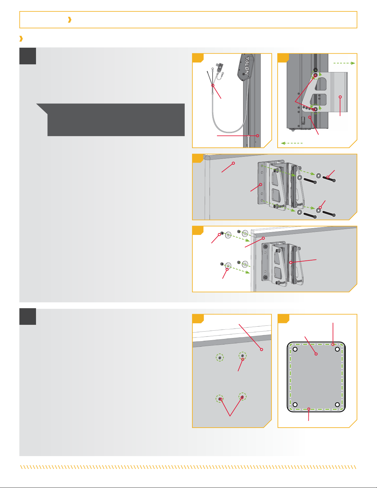
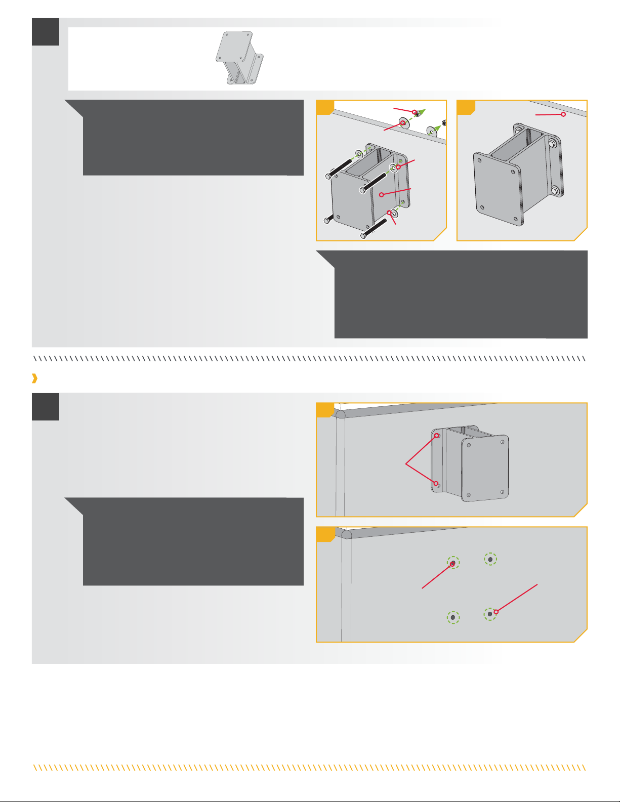
a. Débrancher le Talon de l’alimentation électrique
avant de débuter l’installation.
b. Retirer le Talon du support de montage en
desserrant les quatre écrous Nylock qui maintiennent
le Talon en place. Ne pas retirer les écrous; il suffit
de les desserrer.
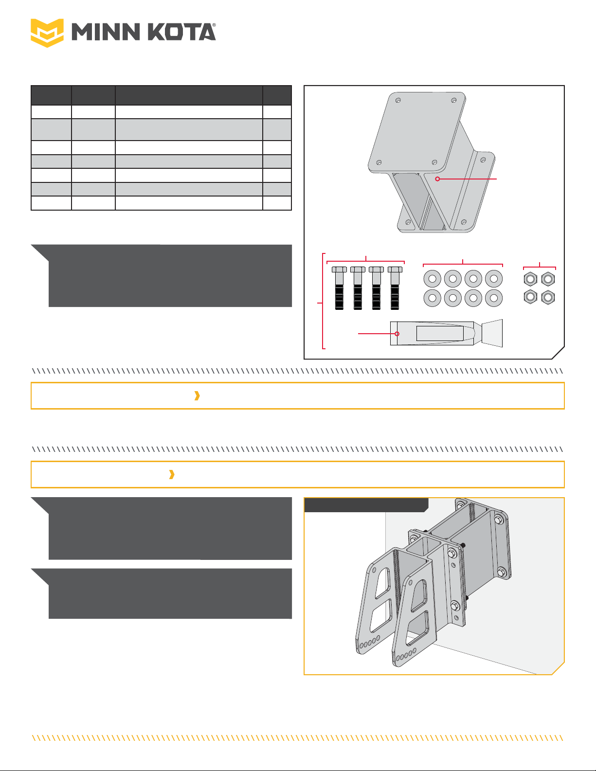
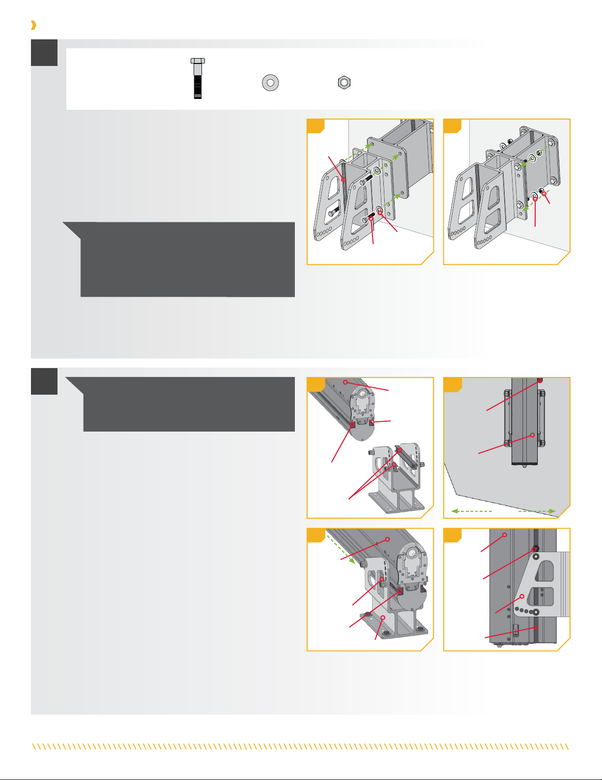
g. Aligner le support de décalage avec les trous de
montage dans le tableau arrière. Selon les trous
utilisés au départ pour installer le support de montage
du Talon, il faudra peut-être percer de nouveaux trous
dans le support de décalage.
h. Appliquer un ruban de 1/8 po (3 mm) de scellant
de qualité marine (non compris) autour des trous
de montage du tableau arrière du bateau, où se
trouvaient la quincaillerie et le support de montage
avant de les enlever.
i. Placer le scellant de qualité marine sur la surface
du support de décalage qui sera en contact avec le
tableau arrière du bateau, une fois monté. Garder le
scellant centré approximativement entre la bordure
extérieure du support de décalage et les trous de
montage. Lorsque le scellant est en place, aligner le
support de décalage dans l’orientation désirée avec
les trous qui étaient percés dans le tableau arrière.
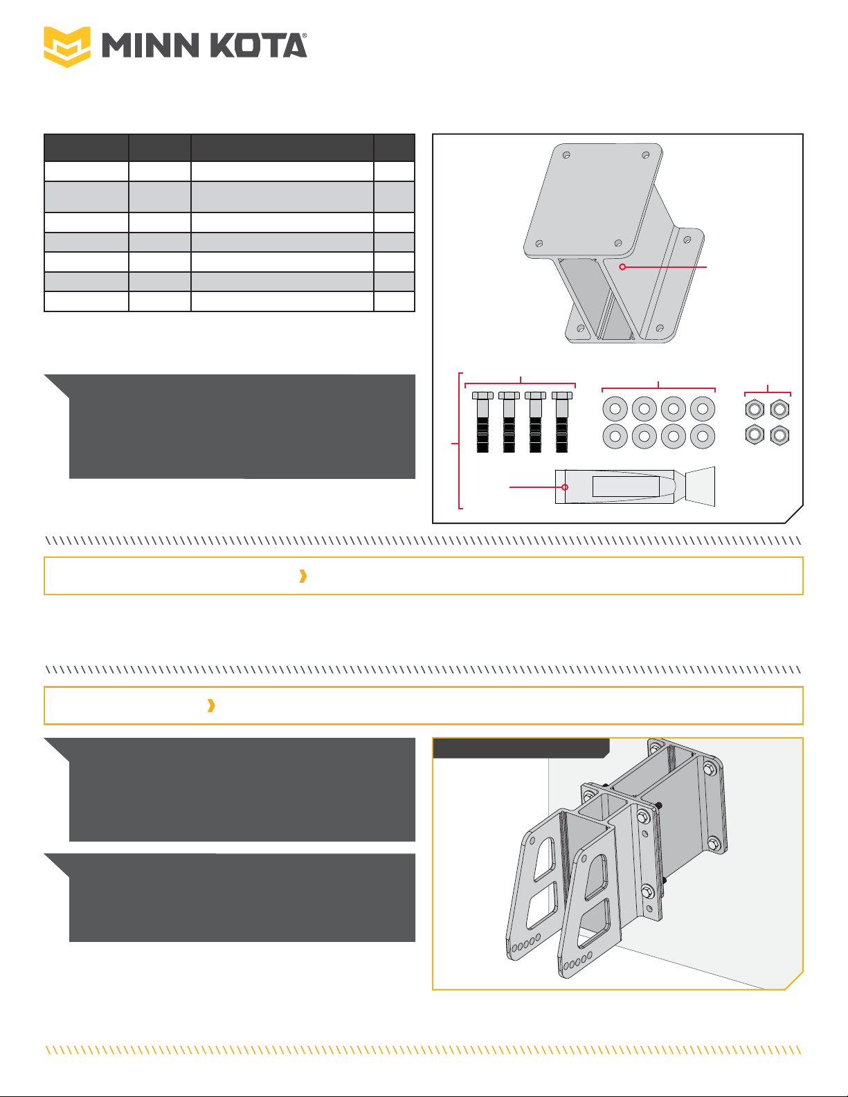
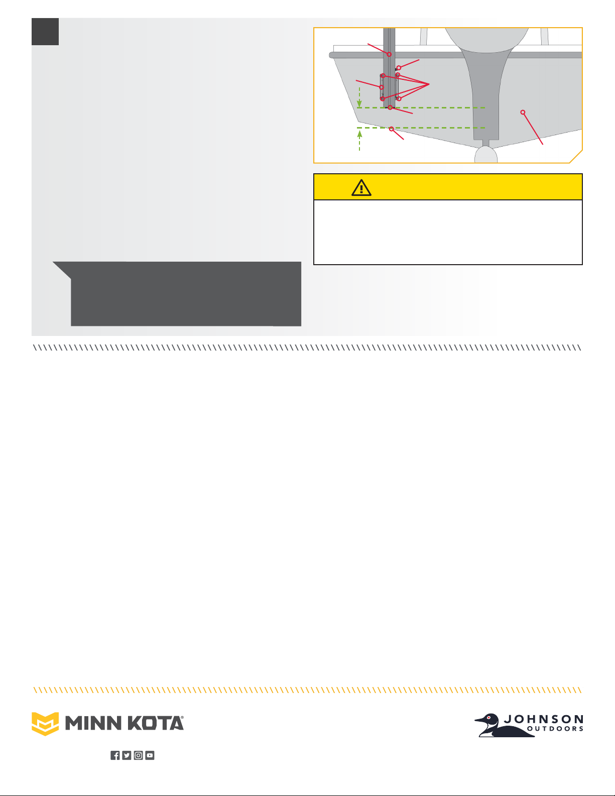
Installation avec un Talon déjà installé
TableauTableau
arrièrearrière
SupportSupport
de montagede montage
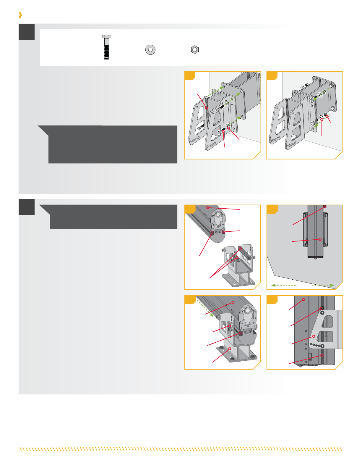
Boulon deBoulon de
montagemontage
RondelleRondelle
plateplate
1
22g
Scellant deScellant de
qualité marinequalité marine
Trou de montageTrou de montage
Tableau arrièreTableau arrière
1e
1b1a
TalonTalon
Support deSupport de
montagemontage
TalonTalon
TalonTalon
CordonCordon
d’alimentationd’alimentation
ÉcrouÉcrou
NylockNylock
En-bordEn-bord
Hors-bordHors-bord
INSTALLATION
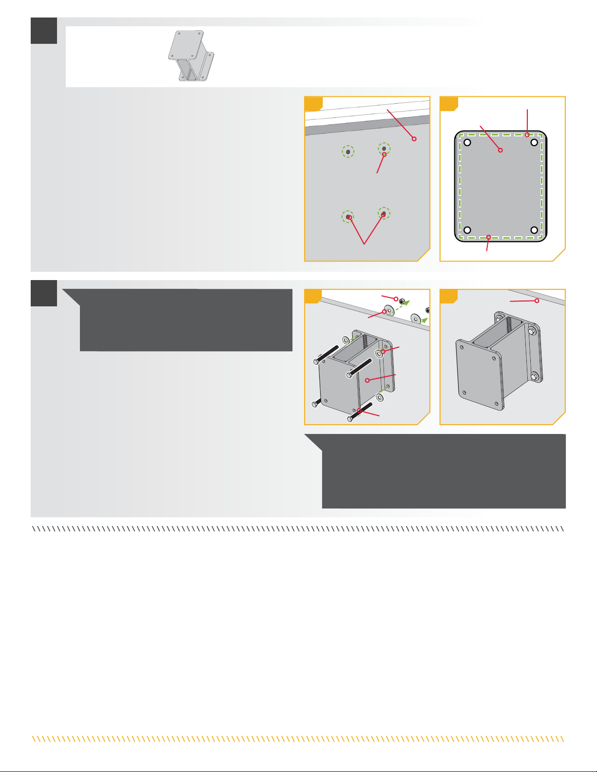
AVIS : Il peut être nécessaire d’avoir une deuxième
personne disponible pour tenir le Talon pendant le
desserrage des écrous Nylock.
c. Sortir le Talon en le soulevant du support de
montage et le mettre de côté, en veillant à ce
qu’il y ait suffisamment de jeu dans le cordon
d’alimentation pour le faire. Si acheminé par le
tableau arrière, le cordon d’alimentation n’a pas
besoin d’être tiré à travers le tableau arrière pour
terminer l’installation.
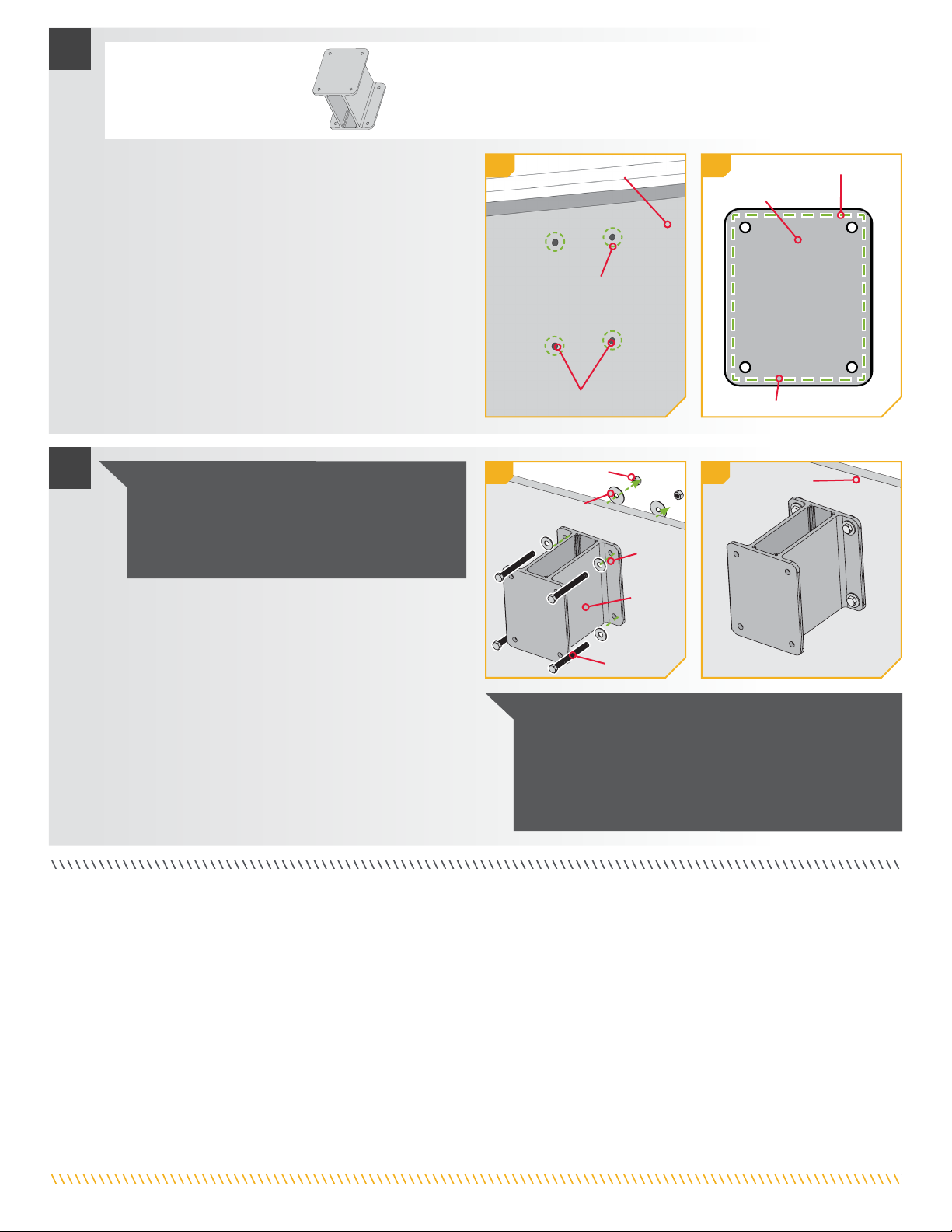
d. À l’aide d’une clé à cliquet ou à douille 1/2 po (12,7
mm), retirer les quatre écrous Nylock et les rondelles
de protection sur le côté du tableau arrière qui
retiennent les boulons de montage en place.
e. Retirer les quatre boulons de montage 5/16 po (7,9
mm) x 3 1/2 po (89 mm) qui fixent le support de
montage au tableau arrière. Ces mêmes boulons
seront utilisés pour fixer le support de décalage de 6
po (15,2 cm) au tableau arrière.
f. Conserver les écrous Nylock, les rondelles de
protection, les rondelles plates et les boulons de
montage pour fixer le support de décalage de 6 po
(15,2 cm) au tableau arrière.
2h
Support de
décalage
Scellant de qualité marineScellant de qualité marine
ÉcrouÉcrou
NylockNylock
Rondelle deRondelle de
protectionprotection
TableauTableau
arrièrearrière Support deSupport de
montagemontage
1f

9 | minnkotamotors.com ©2020 Johnson Outdoors Marine Electronics, Inc.
a. Relire les facteurs de montage afin de déterminer
s’il est acceptable d’effectuer un montage direct du
support de montage du Talon. Si acceptable, placer
le support de décalage à l’emplacement sélectionné
et marquer les trous de montage avec un crayon ou
un outil de marquage semblable. Les quatre trous de
montage doivent être marqués et utilisés.
Installation sans Talon installé (nouvelle installation)
1
1b
EmplacementsEmplacements
marquésmarqués
EmplacementEmplacement
percépercé
Trous deTrous de
montagemontage
1a
c. Installer le support de décalage de 6 po (15,2 cm)
(article nº 2) au tableau arrière au moyen de la
quincaillerie de montage retirée lors de l’installation
précédente. Les boulons de montage devraient
passer à travers les rondelles plates, le support de
décalage, puis dans le tableau arrière.
d. Fixer chaque boulon de montage avec une rondelle
de protection et un écrou Nylock. Une fois le support
en position, serrer la quincaillerie de montage avec
une clé polygonale ou à cliquet de 1/2 po (12 mm).
3
3f 3g
SupportSupport
dede
décalagedécalage
Boulon deBoulon de
montagemontage
TableauTableau
arrièrearrière
Rondelle deRondelle de
protectionprotection
RondelleRondelle
plateplate
ÉcrouÉcrou
NylockNylock
ARTICLE(S) REQUIS
#2 x 1
AVIS : Pour prévenir le grippage de la quincaillerie
en acier inoxydable, ne pas utiliser d’outils haute
vitesse pour l’installation. Le fait de mouiller les vis
ou d’appliquer un produit antigrippant peut aider à
prévenir qu’elles grippent.
AVIS: La quincaillerie de montage du Talon comprend :
quatre boulons de mon-tage (nº 2373525), quatre rondelles
plates (nº 2371749), quatre rondelles de protection (nº
2371752) et quatre écrous Nylock (nº 2223100). Cette
quincaillerie se trouve dans le sac de quincaillerie du Talon
(nº 2994903).
AVIS : Avant de percer des trous dans le tableau
arrière, tenir compte des facteurs de montage
qui se trouvent à la section « Installation » du
manuel du propriétaire de Talon ou des directives
d’installation. On peut les trouver en ligne sur
www.minnkotamotors.com.
b. Revérifier que l’emplacement de montage est
dégagé pour percer les trous, ensuite utiliser une
perceuse avec une mèche de 5/16 po (7,9 mm) pour
percer le tableau arrière/la poupe du bateau aux
emplacements marqués.

10 | minnkotamotors.com ©2020 Johnson Outdoors Marine Electronics, Inc.
c. Placer un cordon de 1/8 po (3 mm) de scellant de
qualité marine (non compris) sur le tableau arrière du
bateau, autour des trous de montage percés.
d. Placer le scellant de qualité marine sur la surface
du support de décalage de 6 po (15,2 cm) (article
nº 2) qui sera en contact avec le tableau arrière du
bateau, une fois monté. Garder le scellant centré
approximativement entre la bordure extérieure
du support de décalage et les trous de montage.
Lorsque le scellant est en place, aligner le support de
décalage dans l’orientation désirée avec les trous qui
étaient percés dans le tableau arrière/la poupe.
2
2d 2e
Scellant de qualitéScellant de qualité
marinemarine
Trou de montage percéTrou de montage percé
TableauTableau
arrièrearrière Support de décalage
Scellant de qualité marineScellant de qualité marine
e. Installer le support de décalage sur le tableau arrière
au moyen de la quincaillerie de montage livrée avec
le Talon. Les boulons de montage devraient passer à
travers les rondelles plates, le support de décalage,
puis dans le tableau arrière.
f. Fixer chaque boulon de montage avec une rondelle
de protection et un écrou Nylock. Une fois le support
en position, serrer la quincaillerie de montage avec
une clé polygonale ou à cliquet de 1/2 po (12 mm).
33f 3g
SupportSupport
dede
décalagedécalage
Boulon deBoulon de
montagemontage
TableauTableau
arrièrearrière
Rondelle deRondelle de
protectionprotection
RondelleRondelle
plateplate
Écrou NylockÉcrou Nylock
ARTICLE(S) REQUIS
#2 x 1
AVIS : Pour prévenir le grippage de la quincaillerie
en acier inoxydable, ne pas utiliser d’outils haute
vitesse pour l’installation. Le fait de mouiller les vis
ou d’appliquer un produit antigrippant peut aider à
prévenir qu’elles grippent
AVIS : La quincaillerie de montage du Talon comprend :
quatre boulons de montage (nº 2373525), quatre rondelles
plates (nº 2371749), quatre rondelles de protection (nº
2371752) et quatre écrous Nylock (nº 2223100). Cette
quincaillerie se trouve dans le sac de quincaillerie du Talon
(nº 2994903).

11 | minnkotamotors.com ©2020 Johnson Outdoors Marine Electronics, Inc.
Terminer l’installation
a. Aligner le support de montage du Talon avec le
support de décalage 6 po (15,2 cm).
b. Fixer le support de montage au moyen des quatre
boulons en acier inoxydable (article nº 4) et quatre
rondelles (article nº 6). Les boulons de montage
devraient passer à travers les rondelles, le support
de montage puis dans le support de décalage 6 po
(15,2 cm).
1ARTICLE(S) REQUIS
#4 x 4 #6 x 8 #8 x 4
Support deSupport de
montagemontage
RondelleRondelle
Boulon en acierBoulon en acier
inoxydableinoxydable
1b 1c
d. L’assemblage du Talon doit être installé sur le
support de montage. Prendre l’ensemble du Talon et
remarquer qu’il y a une piste d’assemblage située sur
les deux côtés du Talon.
e. Lorsque le Talon est bien orienté comme il le serait
une fois installé, il y a un boulon de blocage vertical
unique situé sur le côté tribord du Talon, longeant la
piste d’assemblage. Le boulon de blocage vertical est
utilisé comme point de référence ou de guidage pour
bloquer le Talon et placer les sangles de montage
dans la piste d’assemblage. S’assurer que le boulon
de blocage vertical est fixé dans la position finale
approximative.
f. Lever avec précaution l’assemblage du Talon dans
le support de montage et aligner les sangles de
montage avec la piste d’assemblage. Faire glisser les
rondelles de sûreté sur la paroi intérieure du support
de montage afin qu’elles soient entre le support et
l’assemblage du Talon. Faire glisser l’assemblage
du Talon vers le bas sur les pistes d’assemblage
jusqu’à ce qu’il soit en contact avec le boulon de
blocage vertical.
Piste
d’assemblage
Assemblage
du Talon
Piste
d’assemblage
PistePiste
d’assemblaged’assemblage PistePiste
d’assemblaged’assemblage
Assemblage
du Talon
Assemblage
du Talon
AssemblageAssemblage
du Talondu Talon
Boulon deBoulon de
blocageblocage
verticalvertical
Boulon deBoulon de
blocageblocage
verticalvertical
Sangles de
montage
Support de montageSupport de montage
Support deSupport de
montagemontage
Sangles deSangles de
montagemontage
BâbordBâbord TribordTribord
2d 2e
2f 2f
AVIS : On recommande qu’une deuxième
personne vous aide avec cette étape lors de
l’installation.
2
RondelleRondelle
ÉcrouÉcrou
NylockNylock
AVIS : Pour prévenir le grippage de la quincaillerie
en acier inoxydable, ne pas utiliser d’outils haute
vitesse pour l’installation. Le fait de mouiller les vis
ou d’appliquer un produit antigrippant peut aider à
prévenir qu’elles grippent.
c. Fixer les vis avec quatre rondelles plates (article nº
6) et quatre écrous Nylock (article nº 8). Serrer à
20 pi-lb au moyen de la clé polygonale 1/2 po (12,7
mm) ou à douille.

3g. En soutenant l’assemblage du Talon, l’ajuster, ainsi
que le boulon de blocage vertical, vers le haut et le
bas, dans le support de montage afin que le bas de
l’assemblage du Talon soit à au moins 4 po (10,2
cm) au-dessus du bas de la coque du bateau, ou de
la ligne d’eau du bateau. Une fois en place, serrer
temporairement le boulon de blocage vertical.
h. Revérifier le placement de l’assemblage du Talon et
s’assurer qu’il respecte les consignes de montage.
Faire tout ajustement nécessaire. Lorsque la position
de l’assemblage du Talon est acceptable, fixer les
quatre vis à tête creuse hexagonale et les écrous
Nylock qui tiennent les sangles de montage avec une
clé polygonale ou à cliquet de 9/16 po (14,3 mm).
Utiliser une clé à cliquet pour serrer à un couple de
serrage de 20 à 30 pi-lb (27 à 40 Nm). Serrer le
boulon de blocage vertical.
AVIS : Pour obtenir des détails sur les ajustements
de montage du Talon, consulter le manuel du
propriétaire ou les directives d’installation en ligne sur
minnkotamotors.com.
ATTENTION
Vérifier la tension des quatre écrous d’ajustement vertical après
la première utilisation, et périodiquement après, afin d’assurer
qu’ils sont au couple de serrage recommandé de 20 à 30 pi-lb
(27 à 40 Nm).
Boulon deBoulon de
blocage verticalblocage vertical
Support deSupport de
décalagedécalage
AssemblageAssemblage
du Talondu Talon
Support deSupport de
montagemontage
Bordure inférieureBordure inférieure
du Talondu Talon
CoqueCoque
Coque directementCoque directement
sous le Talonsous le Talon
Minimum de 4 poMinimum de 4 po
(101,6 mm)(101,6 mm)
Minn Kota Consumer & Technical Service
Johnson Outdoors Marine Electronics, Inc.
PO Box 8129
Mankato, MN 56001
121 Power Drive
Mankato, MN 56001
Phone (800) 227-6433
Fax (800) 527-4464
minnkotamotors.com
©2020 Johnson Outdoors Marine Electronics, Inc.
All rights reserved.
Part #2374929 Rev E 06/20ECN 40714
Pour obtenir des renseignements sur la garantie, visiter minnkotamotors.com.
Table of contents
Languages:
Other MINN KOTA TV Mount manuals

MINN KOTA
MINN KOTA MKA-48 User manual

MINN KOTA
MINN KOTA 1810360 User manual

MINN KOTA
MINN KOTA MKA-57 User manual

MINN KOTA
MINN KOTA TALON User manual

MINN KOTA
MINN KOTA MKA-56 User manual

MINN KOTA
MINN KOTA MKA-48 User manual

MINN KOTA
MINN KOTA MKA-16-03 User manual

MINN KOTA
MINN KOTA MKA-47 User manual

MINN KOTA
MINN KOTA MKA-16-03 User manual

MINN KOTA
MINN KOTA MKA-51 User manual