Minuteman 957718 User manual

Operating Instructions 1 01370E
®
BATTERY CHARGER
PART NO. 957718
PLEASE SAVE THESE IMPORTANT SAFETY AND OPERATING INSTRUCTIONS
For correct operation of the equipment, it is important to read and be familiar
with this entire manual before installing and operating the charger.
DO NOT DISCARD THIS MANUAL AFTER READING.
LOOK FOR THIS SYMBOL TO POINT OUT SAFETY PRECAUTIONS. IT MEANS:
BECOME ALERT—YOUR SAFETY IS INVOLVED.
IF YOU DO NOT FOLLOW THESE
SAFETY INSTRUCTIONS, INJURY OR PROPERTY DAMAGE CAN OCCUR.
INTRODUCTION
This battery charger is designed to recharge deep-
cycle, lead-acid batteries. A ferroresonant
transformer is used to provide a highly reliable, line
compensating unit with a minimum of moving parts,
designed for long, trouble-free service. A patented
electronic timer turns the charger on and off
automatically. This electronic timer determines full
charge of the batteries by measuring the rate at
which the battery voltage increases during charge.
When the voltage stops rising, the battery is fully
charged and the charger turns off.
INITIAL INSTALLATION
The AC line to which the charger is to be connected
must be of the proper voltage as indicated on the
nameplate of the charger and in TABLE 1. The line
must also be capable of supplying 15 amperes to
this charger. TABLE 1
Part No. Input Voltage
957718 120
CAUTION: TO REDUCE THE RISK OF FIRE
USE THIS CHARGER ONLY ON CIRCUITS
PROVIDED WITH A MAXIMUM OF 20 AMPERE
BRANCH CIRCUIT PROTECTION (CIRCUIT
BREAKER OR FUSE), IN ACCORDANCE WITH
THE NATIONAL ELECTRICAL CODE, ANSI/NFPA
70, AND ALL LOCAL CODES AND ORDINANCES.
The use of an extension cord with the charger
should be avoided.
The use of an improper extension cord could result
in a risk of fire or electric shock. If an extension cord
must be used, use a three-conductor, No. 12 AWG
cord with ground, properly wired, in good electrical
condition and keep it as short as possible. Make
sure that the pins on the plug of the extension cord
are the same number, size, and shape as that of the
plug on the battery charger.
Locate all cords so that they will not be stepped on,
tripped over, or otherwise subject to damage or
stress.
Do not operate this charger with a damaged cord or
plug. Do not operate this charger if it has received a
sharp blow, was dropped or otherwise damaged in
any manner; refer to a qualified service agent.
Provide adequate ventilation for the batteries and
charger. The convection-cooled design requires an
unobstructed flow of cooling air for proper operation.
Keep all charger ventilation openings at least two
inches (2") (5cm) away from walls and other objects.
Do not allow clothing, blankets, or other material to
cover the charger.
WARNING: CHARGERS CAN IGNITE
FLAMMABLE MATERIALS AND VAPORS. DO
NOT USE NEAR FUELS, GRAIN DUST,
SOLVENTS, THINNERS, OR OTHER
FLAMMABLES.

Operating Instructions 2 01370E
WARNING: KEEP DRY. DO NOT EXPOSE
CHARGER TO RAIN. FOR STORAGE, KEEP IN A
BUILDING. REPLACE WORN, CUT, OR
DAMAGED POWER CORDS OR WIRES
IMMEDIATELY.
GROUNDING INSTRUCTIONS
This battery charger must be grounded to reduce the
risk of electric shock. This charger is equipped with
an electric cord having an equipment-grounding
conductor and a grounding-type plug. This plug
must be connected to an appropriate receptacle that
is properly installed and grounded in accordance
with the National Electrical Code and all local codes
and ordinances.
DANGER: IMPROPER CONNECTION OF THE
EQUIPMENT-GROUNDING CONDUCTOR CAN
RESULT IN A RISK OF AN ELECTRIC SHOCK.
The conductor with insulation having an outer
surface that is green, with or without yellow stripe(s),
is the equipment-grounding conductor. If repair or
replacement of the electric cord or plug is necessary,
do not connect the equipment-grounding connector
to live terminal.
NORMAL OPERATION
REFER TO, READ, and FOLLOW ALL the
instructions and safety precautions printed on the
charger before every use!
WARNING: DO NOT MAKE ANY
CONNECTIONS UNTIL YOU READ THE
CHARGER NAMEPLATE AND VERIFY THAT THE
CHARGER IS FOR USE ON THE INTENDED
INPUT POWER (BOTH VOLTAGE AND
FREQUENCY), BATTERY SYSTEM VOLTAGE,
BATTERY TYPE, AND BATTERY AMP-HOUR
CAPACITY SIZE!
1. With the charger DC output cord disconnected
from the batteries, connect the power supply
cord to the needed AC voltage and frequency as
specified on the charger nameplate.
WARNING: TO REDUCE THE RISK OF AN
ELECTRIC SHOCK, CONNECT THE AC POWER
SUPPLY PLUG ONLY TO A PROPERLY
GROUNDED, SINGLE PHASE (3-WIRE) OUTLET.
REFER TO GROUNDING INSTRUCTIONS.
CAUTION: MAKE SURE THE BATTERY
PACK IS THE CORRECT NUMBER OF SERIES
CONNECTED LEAD-ACID CELLS, SYSTEM
VOLTAGE, AND AMP-HOUR CAPACITY AS
SPECIFIED ON THE CHARGER. USE
OTHERWISE MAY DAMAGE THE CHARGER
AND/OR BATTERIES.
DANGER: TO PREVENT ELECTRIC SHOCK,
DO NOT TOUCH UNINSULATED PARTS OF THE
CHARGER OUTPUT CONNECTOR, BATTERY
CONNECTOR, OR BATTERY TERMINALS. MAKE
SURE THAT BOTH THE CHARGER AND
BATTERY CONNECTORS ARE IN GOOD
WORKING CONDITION.
DANGER: DO NOT USE THE CHARGER IF
EITHER THE CHARGER OR BATTERY
CONNECTORS ARE CORRODED, CRACKED,
SHOW ANY SIGNS OF MELTING, ARE
DAMAGED IN ANY WAY OR DO NOT MAKE A
TIGHT CLEAN ELECTRICAL CONTACT. USING
ANY CHARGER WITH ANY OF THE ABOVE
SYMPTOMS COULD RESULT IN A FIRE,
PROPERTY DAMAGE, OR PERSONAL INJURY.
REPLACE DEFECTIVE, CRACKED OR
DAMAGED CORDS OR WIRES IMMEDIATELY.
DO NOT DISASSEMBLE CHARGER; TAKE IT TO
A QUALIFIED SERVICE AGENT WHEN SERVICE
OR REPAIR IS REQUIRED. INCORRECT
REASSEMBLY MAY RESULT IN A RISK OF
ELECTRIC SHOCK OR FIRE.
2. Connect the charger to a battery system of the
voltage, type, and amp-hour capacity as
specified on the charger. Connect DC output
connector to the battery connector by grasping
the plug body or handle and firmly pushing the
plug straight into the receptacle until the
connectors are fully engaged.
WARNING: DO NOT DISCONNECT THE DC
OUTPUT CONNECTOR FROM THE BATTERY
RECEPTACLE WHEN THE CHARGER IS
OPERATING. THE RESULTING ARCING AND
BURNING OF THE PLUG AND RECEPTACLE
COULD CAUSE THE BATTERIES TO EXPLODE
AND WILL DAMAGE THE CONNECTORS. IF THE
CHARGER MUST BE STOPPED, DEPRESS THE
STOP BUTTON UNTIL THE AMMETER
DECREASES TO ZERO OR DISCONNECT THE
AC PLUG FROM ITS RECEPTACLE. ONLY
AFTER THE AMMETER HAS DROPPED TO
ZERO, THEN DISCONNECT THE CHARGER DC
OUTPUT PLUG FROM THE BATTERY
RECEPTACLE.
Distinct steps occur in the process of the
charger turning on and charging. Pay attention
to these steps and monitor the initial charge rate
on the ammeter at the instant the charger starts
charging.
Three to five (3-5) seconds after the charger and
battery connectors are engaged, the control
relay inside the charger will pull in with a "click",

Operating Instructions 3 01370E
indicating complete electrical circuits between
the electronic timer inside the charger to the
equipment battery pack as well as to live AC
power.
After the control relay pulls in with a click, the
transformer will hum, indicating that the
transformer has been energized by AC power.
After the transformer hums, the ammeter needle
will deflect, indicating initial charge rate.
3. Monitor the ammeter for the initial charge rate.
The correct initial charge rate will vary due to
numerous factors. Refer to the chart to
determine the minimum and maximum initial
charge rate for the specific current rating
charger.
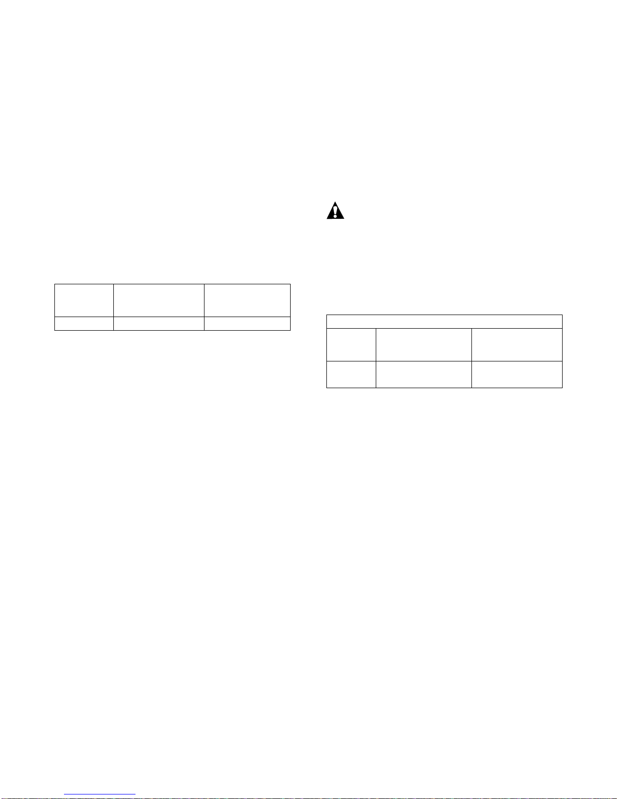
CORRECT INITIAL CHARGE RATE
Charger Current
Rating Minimum Start
Rating Maximum
40 31 40 48
If the batteries are heavily discharged and the
AC input line voltage is higher than nominal, the
initial charge rate may exceed the maximum
initial charge rate for the specific current rating
charger. Under normal conditions, the charge
rate will decrease to or less than the specified
maximum charge rate in less than 120 minutes.
If the ammeter still reads in excess of the
specified maximum charge rate after 120
minutes, turn the charger off by depressing the
STOP button until the ammeter decreases to
zero or disconnecting the AC plug from its
receptacle.
CAUTION: TO PREVENT BATTERY
DAMAGE, CHARGER OVERHEATING AND
TRANSFORMER BURN OUT, DO NOT ALLOW
THE CHARGER TO OPERATE FOR MORE THAN
120 MINUTES WITH THE AMMETER READING IN
EXCESS OF THE SPECIFIED MAXIMUM CHARGE
RATE. THIS MISUSE WILL CAUSE OVER-
HEATING AND TRANSFORMER BURNOUT WILL
RESULT.
This high charge rate is caused if the charger is
connected to a battery pack with a system
voltage lower than, or Amp-Hour capacity
greater than, specified on the charger. If battery
maintenance has recently been performed, test
to see if an individual battery in the battery pack
has been connected reverse polarity. A
common error is to install one or more of the 6
volt batteries in a battery pack in reverse
polarity. Using a suitable DC voltmeter, test to
be sure all batteries in a battery pack are
correctly installed, and also test by measuring
the battery system voltage at the equipment
battery connector, and compare it to the system
voltage specified in the charger nameplate.
After charging for 120 minutes at this excessive
rate, the measured on-charge voltage should
rise to the voltage specified by the charger
nameplate. Voltage measurements, while
charging, lower than the charger system voltage
indicates an incorrect or failed battery pack that
must be corrected before using the charger.
If the batteries have been recently charged, the
battery is cold (temperature below 65°F), or the
AC input voltage is lower than nominal, the initial
charge rate may only reach the minimum initial
charge rate at turn-on for the specific current
rating charger.
If the initial charge rate is less than half of the
specified minimum initial charge rate at the
moment of turn-on, the charger may be
malfunctioning due to electrical overload
damage. Turn the charger off by depressing the
STOP button until the ammeter decreases to
zero or disconnecting the AC plug from its
receptacle.
CAUTION: DO NOT USE THE CHARGER IF
THE OUTPUT IS LOW. BATTERIES WILL NOT
REACH FULL CHARGE, THEREBY INCREASING
THE POSSIBILITY OF A HARMFUL DEEP
DISCHARGE DURING THEIR NEXT USE.
This too low a charge rate at the instant of turn-
on can be due to a battery pack system voltage
that is higher than specified on the charger, a
charger malfunction resulting from electrical
overload damage, or component failure. Test
for the correct battery pack system voltage with
a suitable voltmeter at the equipment battery
connector and compare with the system voltage
specified on the charger nameplate.
DANGER: TO REDUCE THE RISK OF
ELECTRIC SHOCK, ALWAYS DISCONNECT
BOTH THE POWER SUPPLY CORD AND THE
OUTPUT CORD BEFORE ATTEMPTING ANY
MAINTENANCE OR CLEANING.
The charger fuses are located behind the front
panel. DO NOT REMOVE THE FRONT PANEL
FOR INSPECTION WITHOUT FIRST DISCON-
NECTING BOTH THE POWER SUPPLY CORD
AND THE OUTPUT CHARGING CORD. RISK
OF ELECTRIC SHOCK.
Visually inspect and electrically test the fuses. A
blown (OPEN) DC fuse indicates an electrical
overload damage caused short circuit failure of a
rectifier diode or reverse polarity connection of
the charger to the batteries. Melted fuses or
fuse links can result from weak fuseholders or
fuseholder connections.

Operating Instructions 4 01370E
LOCATE AND CORRECT CAUSE OF
TROUBLE BEFORE REPLACING A BLOWN
FUSE.
DO NOT DISASSEMBLE THE CHARGER.
Take the charger to a qualified service agent to
have the heatsink assembly with diodes and
correct replacement fuse, fuseholder or fuse
assembly installed. Incorrect reassembly may
result in a risk of electric shock or fire.
During the charge, the battery voltage gradually
increases which causes the charge rate to
decrease. Batteries able to deliver their full
rated capacity will still rise to 2.5 volts per cell, or
higher, at 80°F, as they reach maximum charge.
This will allow the charge current to decrease or
taper to the charger's designed finish charge
rate or lower at the end of charge. Refer to
chart.
Charger
Current
Rating
Finish Current
@ 2.5 Volts/Cell
@80°°F (27°°C)
Normal Finish
Charge
Current Range
40 Amps 10 Amps 13 Amps or less
Since each battery cell accepts charge at a
slightly different rate, charging with the ammeter
reading in the normal finish charge range for the
last few hours of charge is important to achieve
equalization of all battery cells every time the
batteries are charged.
As batteries wear out and lose capacity, the end
of charge finish voltage continually decreases.
As the end of charge finish voltage decreases to
less than 2.5 volts per cell, this prevents the
finish charge current from decreasing to the
normal finish charge current range. The
electronic timer still determines when the
batteries have reached their now reduced
maximum charge capacity and will turn the
charger off.
The major factors affecting the required charge
time are charger output current rating, battery
size or capacity in amp-hours, and how heavily
the battery is discharged. A larger, more heavily
discharged battery requires more time to
recharge to maximum charge with the same
current rating charger than a smaller, less
heavily discharged battery.
The electronic timer circuit board contains a
section that stops supplying power to the control
relay if the charger operates continuously for 18
hours and is unable to achieve maximum
charge. The indicator light will blink if maximum
time charge termination occurs. The indicator
light will glow steady for normal charge
termination in 18 hours or less.
If no power outage occurred and the charger
operated continuously longer than 18 hours,
either the control relay is stuck or the electronic
timer circuit board is malfunctioning.
WARNING: DO NOT LEAVE THE CHARGER
DC OUTPUT CONNECTOR CONNECTED TO THE
BATTERY CONNECTOR WHILE UNATTENDED
FOR TWO DAYS OR MORE IN A ROW. SEVERE
OVERCHARGING AND POSSIBLE DAMAGE TO
THE BATTERIES WILL RESULT IF THE
CHARGER SHOULD FALL TO TURN OFF, OR
TURN BACK ON.
APPROXIMATE RECHARGE TIMES
Part
No. Battery Capacity
Ampere Hours
6 Hr. Scale
Approximate
Recharge Time
(Hours)
957718 230
440 9
18
Newer or colder batteries require greater energy
return, are slower to respond, and consequently
require extended charge time at a low finish
charge current rate to return to maximum
charge. As batteries wear out and lose capacity,
their temperature rise both from use and on
charge becomes significant as an indicator of
the end of life and the battery cannot benefit
from extended charge time. Even though they
are properly charged, older batteries continually
lose capacity, and should be replaced when they
will no longer perform as desired. Very weak
batteries are indicated when the charger turns
off after only 8 hours and the indicator light is
blinking.
4. At the finish of charge, monitor the indicator
light, read the ammeter, note the run time, and
listen for transformer hum. Refer to the
following chart.

Operating Instructions 5 01370E
Indicator Light Ammeter Drop
to Zero Charging Run
Time Transformer
Hum
Steady Glow Yes 18 Hours or less No MAXIMUM CHARGE ACHIEVED
Flashing Yes 9 Hours No VDC less than 2.25 V/cell in 9 hours
WEAK BATTERY SYSTEM
--- OR ---
Flashing Yes 18 Hours No Too large amp-hour capacity battery system or excessive
discharge
MAXIMUM CHARGE NOT ACHIEVED
Steady or
Flashing No Yes Malfunction; Relay Stuck or Electronic Timer Failure
TURN OFF CHARGER BY DISCONNECTING CORD
After the charger has turned off, disconnect the
charger DC output connector from the battery
connector by grasping the plug body or handle
and pulling the plug straight out of the
receptacle.
WARNING: TO AVOID DAMAGE TO THE
CHARGER CORD CONNECTOR PLUG, AND
BATTERY CONNECTOR RECEPTACLE, DO NOT
PULL ON THE CHARGER CORD. DO NOT
TWIST, ROCK, OR PULL THE CONNECTOR
PLUG SIDEWAYS.
ON-DEMAND CHARGING
Battery cycle life is directly determined by severity of
use. A battery that has 100% of its available energy
discharged every time it is used will wear out twice
as fast as a battery that has 70% of its available
energy discharged every time it is used. In severe
use situations, some additional battery life can be
realized by instituting short charge periods during
work breaks. This reduces the incidence of full
100% battery depletion before charging.
Follow "Normal Operation" procedures to begin a
short charge period. At the end of any short charge
period where the charger has not turned off, turn the
charger off by depressing the STOP button until the
ammeter decreases to zero or disconnect the AC
plug from its receptacle.
BATTERY STORAGE MAINTENANCE
When the equipment is not in use, charge the
batteries once each week. Remove the DC output
connector at the end of charge.
STORAGE
When the machine is not in use, charge the batteries
once each week.
PROPER CARE OF MOTIVE POWER BATTERIES
Motive power batteries are subjected to severe deep
cycle duty on a daily basis. Although these batteries
are designed to withstand such duty, the following
precautions must be observed to obtain good
performance and maximum cycle life.
CAUTION: ALWAYS WEAR PROTECTIVE
EYE SHIELDS AND CLOTHING WHEN WORKING
WITH BATTERIES. BATTERIES CONTAIN ACIDS
WHICH CAN CAUSE BODILY HARM. DO NOT
PUT WRENCHES OR OTHER METAL OBJECTS
ACROSS THE BATTERY TERMINAL OR
BATTERY TOP. ARCING OR EXPLOSION OF
THE BATTERY CAN RESULT.
1. When installing new batteries, be sure the
polarity of each battery and overall battery pack
is correct. Due to the electrical characteristics
of this charger, it is possible to improperly hook
up the batteries and not blow the fuse when
charging. Battery and/or charger damage can
result.
2. New batteries should be given a full charge
before their first use because it is difficult to
know how long the batteries have been stored.
3. Limit the use of new batteries for the first five
cycles. New batteries are not capable of their
rated output until they have been discharged
and charged a number of times.
4. Do not excessively discharge the batteries.
Excessive discharge can cause polarity
reversal of individual cells resulting in complete
failure shortly thereafter. Limited use of new
batteries will minimize the risk of cell reversals.
5. Maintain the proper electrolyte level by adding
water when necessary. Never allow the
electrolyte level to fall below the top of the
battery plates. Electrolyte levels fall during
discharge and rise during charge. Therefore, to

Operating Instructions 6 01370E
prevent the overflow of electrolyte when
charging, it is mandatory that water be added to
cells AFTER they have been fully charged; do
not overfill. Old batteries require more frequent
additions of water than do new batteries.
6. When the temperature falls below 65°F, the
batteries should be placed on charge as soon
after use as possible.
7. The tops of the batteries and battery hold-
downs must be kept clean and dry at all times
to prevent excessive self-discharge and flow of
current between the battery posts and frame.
8. Follow all operating instructions, cautions, and
warnings as specified in this manual and on the
charger case.

Operating Instructions 7 01370E
WIRING DIAGRAM
green
white
black
AC
FUSE
RELAY
120 Vac
INPUT
yellow
yellow
black
red
brown
brown
orange
orange
blue
green
STOP
LED
TRANSFORMER
DIODES
DIODES
DC FUSE AMMETER
CAPACITOR
red
black
TO
BATTERIES
ELECTRONIC
TIMER
+
-
tan
black
black
tan
1
2
3
4
1
4
7
9
10
11
12
13
14
15
L2120S06
REPLACEMENT PARTS LIST
AMMETER FRONT BOTTOM PANEL
TRANSFORMER CASE ASSEMBLY, COMPLETE
TIMER, ELECTRONIC SWITCH, PUSHBUTTON
HEATSINK ASSEMBLY LED HOLDER
RELAY CAPACITOR, 6 MFD, 660 VAC
FUSE, AC COVER
FUSE, DC BACK PANEL
CONTROL CABLE LEFT SIDE PANEL
FUSEHOLDER RIGHT SIDE PANEL
CORDSET, AC INNER MOUNTING PANEL
CORDSET, DC, SB-175 RED PLUG FUSE PANEL
BASE ASSEMBLY FRONT TOP PANEL

Operating Instructions 8 01370E
L I M I T E D W A R R A N T Y
Minuteman warrants each new Minuteman Battery Charger for defects in material and workmanship for a period of one
year from the date of original purchase of the complete unit. Repairs can be made at the Minuteman factory. To do so send
the defective unit with transportation charges prepaid to:
Minuteman, Inc.
111 South Rohlwing Road
Addison, Illinois 60101
Attention: Service Department
For repairs made at other than the Minuteman factory, Minuteman will provide only the replacement parts. Defective parts
should be sent with transportation charges prepaid to the Minuteman factory at the previously mentioned address.
If the unit or parts are found in the reasonable judgment of Minuteman to be defective in material or workmanship, repair,
or replacement will be made by Minuteman without charge for parts or labor. Repair or replacement will be at the discretion of
Minuteman, with replacements being made using current models or parts performing the equivalent function. Labor charges
other than those incurred at the Minuteman factory are not covered under this warranty. All expenses associated with
delivering defective items to the Minuteman factory and the expense of returning repaired or replaced items from the
Minuteman factory to the owner will be paid for by the owner. All warranty work accomplished at the Minuteman factory will be
completed within a reasonable time after receipt of defective items.
This warranty does not cover any semiconductor parts, such as diodes, which are vulnerable to electrical overloads
beyond the control of Minuteman.
This warranty does not cover any charger that has been subject to misuse, neglect, negligence, or accident, or operated
in any way contrary to instructions specified on the charger case and in the owner's manual. No claim of breach of warranty
shall be cause for cancellation of the contract of sale of any Minuteman charger. Minuteman assumes no responsibility for
loss of time, inconvenience, or other damage, consequential or otherwise, resulting from a defective charger. All implied
warranties (including merchantability) are limited in duration to the one year warranty period.
Some states do not allow the exclusion or limitation of incidental or consequential damages; or limitations on how long an
implied warranty lasts, so the above limitations may not apply to you. This warranty gives you specific legal rights, and you
may also have other rights which vary from state to state.
Minuteman's obligation under this warranty is strictly and exclusively limited to the repair or replacement of defective
items. Minuteman issues this warranty in good faith and with full confidence in the workmanship and quality of Minuteman
products.
Table of contents
Other Minuteman Batteries Charger manuals
Popular Batteries Charger manuals by other brands

Premium
Premium EDT-150-5191 Operation manual

William Sound
William Sound CHG 408 installation instructions

Insignia
Insignia NS-PWL965 user guide

Motorola
Motorola SAC2000-4000CR Quick reference guide

VOLTCRAFT
VOLTCRAFT CQCP-3000 operating instructions

ARJO HUNTLEIGH
ARJO HUNTLEIGH NDA8200 Instructions for use