en-US |2
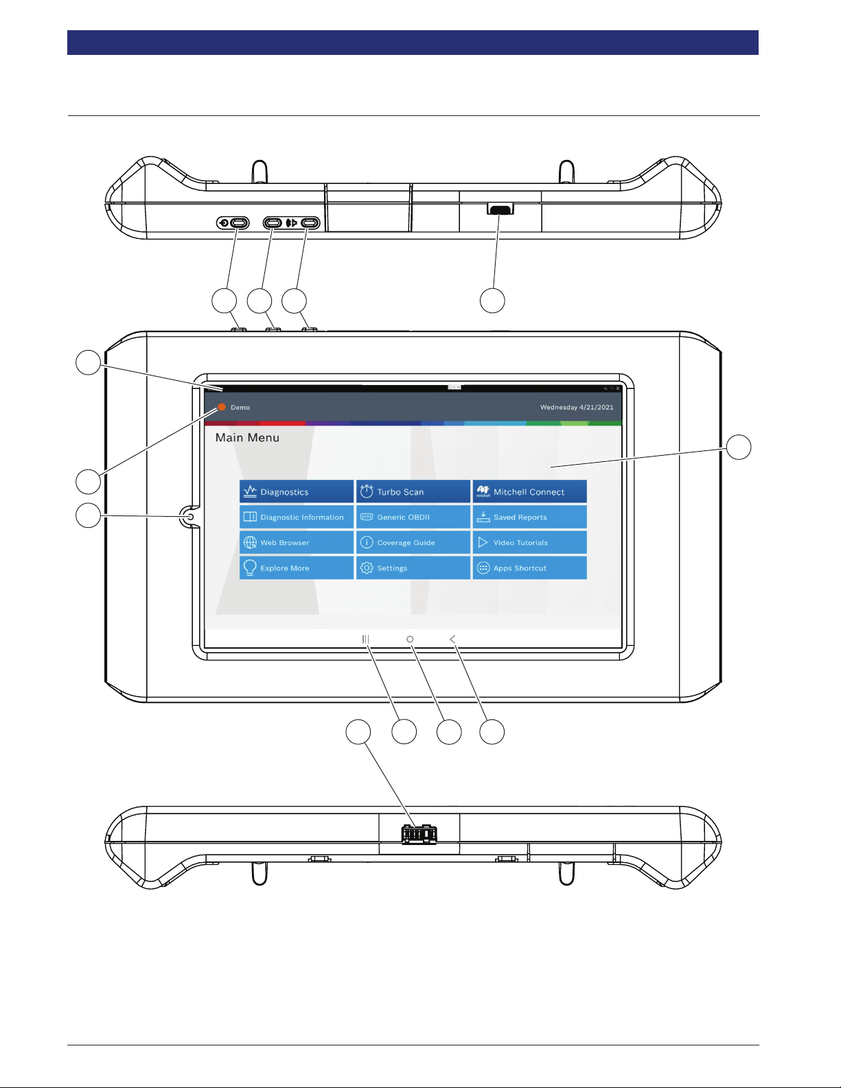
|User Manual | MD-500
1699503426 | REV A | 05.2021 © Mitchell International
Safety Denitions
Follow all DANGER, WARNING, and IMPORTANT messages.
These safety messages are dened as follows:
DANGER or WARNING: Risk of bodily harm
and/or possible loss of life.
IMPORTANT: The information demands special
attention or risks damage to the vehicle or tool.
The safety messages cover situations of which
Bosch Automotive Service Solutions is aware.
Bosch Automotive Service Solutions cannot
know, evaluate, or advise as to all of the
possible hazards. You must be certain that any
conditions or service procedures encountered
do not jeopardize personal safety.
Safety Precautions
DANGER:
When an engine is operating, keep the service
area well ventilated or attach a building
exhaust removal system to the engine exhaust
system. Engines produce carbon monoxide,
an odorless, poisonous gas that causes slower
reaction time and can lead to serious personal
injury or loss of life.
WARNING:
• When working with hydraulic or fuel lines,
be careful that liquids under pressure
do not escape and create a dangerous
condition. Use adequate ventilation
and make sure there are no sparks or
possibility of sparks that may ignite any
vapor.
• Wear an American National Standards
Institute (ANSI) approved eye shield when
testing or repairing vehicles.
• Objects propelled by whirling engine
components or pressurized liquids
escaping may cause personal injury.
• Set the parking brake and block the wheels
before testing or repairing a vehicle. It is
especially important to block the wheels
on front-wheel drive vehicles because
the parking brake does not hold the drive
wheels.
• Do not drive the vehicle and operate the
software at the same time.
• Maintain adequate clearance around
moving components or belts during testing.
• Moving components and belts can
catch loose clothing, body parts, or test
equipment and cause serious damage or
personal injury.
• Automotive batteries contain sulfuric acid
and produce explosive gases that can
result in serious injury due to ignition of
gases. Keep lit cigarettes, sparks, ames,
and other ignition sources away from the
battery at all times.
• Refer to the service manual for the vehicle
being serviced. Adhere to all diagnostic
procedures and precautions Failure to
do so could result in personal injury or
otherwise unneeded repairs.
• Use only specially designed replacement
parts (brake hoses and lines) for ABS
equipped vehicles.
• After bleeding the brake system, check
the brake pedal for excessive travel or a
spongy feel. Bleed again if either condition
is present.
• When installing transmitting devices
(Citizen Band radio, telephone, etc) on
ABS-equipped vehicles, do not locate the
antenna near the ABS control unit or any
other control unit.
• This equipment has been tested and found
to comply with the limits for a Class B
digital device, pursuant to Part 15 of the
FCC Rules. These limits are designed
to provide reasonable protection against
harmful interference in a residential
installation. This equipment generates
and radiates radio frequency energy and,
if not installed and used in accordance
with the instructions, may cause harmful
interference to radio communications.
• To reduce risk of injury, charge only Bosch
Automotive Service Solutions rechargeable
batteries for the tablet product with the
supplied charger. Other types of batteries
may burst causing injury to persons and
property damage.