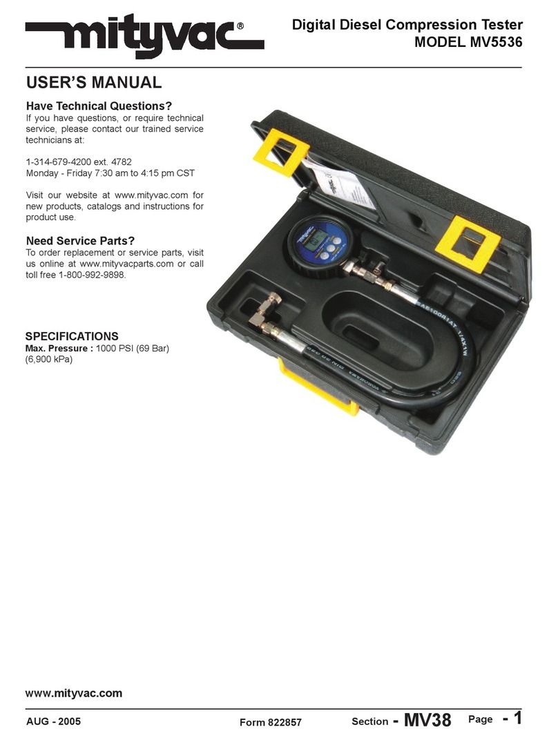
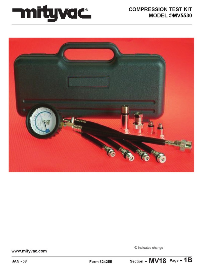
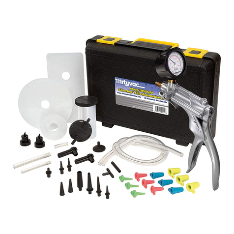
Mityvac MV5545E User manual

APRIL - 2009 Form 824262 Section - MV92-1
USER’S MANUAL
Have a technical question?
Americas:
If you have questions, or require technical
service, please contact our trained service
technicians at:
1-314-679-4200 ext. 4782
Monday – Friday 7:30 am to 4:15 pm CST
Visit our website at www.mityvac.com for
new products, catalogs, and instructions
for product use.
Need service parts?
To order replacement or service parts, visit us
online at www.mityvacparts.com or call toll free
1-800-992-9898.
Europe/Africa:
Heinrich-Hertz-Str 2-8
D-69183 Walldorf
Germany
Phone +49.6227.33.0
Fax +49.6227.33.259
www.lincolnindustrial.de
Asia/Pacific:
25 Int’l Business Park
#01-65 German Centre
Singapore 609916
Phone +65.562.7960
Fax +65.562.9967
For a French or Spanish version of this
manual go to www.MityvacFST.com.
FST PRO FUEL SYSTEM TESTER
MODEL MV5545E

Contents
Safety Precautions. . . . . . . . . . . . . . . . . . . . . . . . . . . . . . . . . . . . . . . . 3
Specifications . . . . . . . . . . . . . . . . . . . . . . . . . . . . . . . . . . . . . . . . . . . . 3
Components, Service Parts, and Accessories . . . . . . . . . . . . . . . . 4
Standard Kit Components . . . . . . . . . . . . . . . . . . . . . . . . . . . . . . . . . . 4
Service Parts . . . . . . . . . . . . . . . . . . . . . . . . . . . . . . . . . . . . . . . . . . . . 5
Fuel System Test Adapters. . . . . . . . . . . . . . . . . . . . . . . . . . . . . . . 6-7
Assembly . . . . . . . . . . . . . . . . . . . . . . . . . . . . . . . . . . . . . . . . . . . . . . . 8
Bypass Hose . . . . . . . . . . . . . . . . . . . . . . . . . . . . . . . . . . . . . . . . . . 8
Proper Use, Care, and Servicing . . . . . . . . . . . . . . . . . . . . . . . . . . . . 8
Setup and Installation . . . . . . . . . . . . . . . . . . . . . . . . . . . . . . . . . . . . . 9
Determining Where to Install the FST. . . . . . . . . . . . . . . . . . . . . . . . . 9
Inline Connection. . . . . . . . . . . . . . . . . . . . . . . . . . . . . . . . . . . . . . . 9
Alternative Connection Locations . . . . . . . . . . . . . . . . . . . . . . . . . . 9
Installation. . . . . . . . . . . . . . . . . . . . . . . . . . . . . . . . . . . . . . . . . . . . . .10
Testing and Diagnostics . . . . . . . . . . . . . . . . . . . . . . . . . . . . . . . . . . 12
Return Fuel Systems . . . . . . . . . . . . . . . . . . . . . . . . . . . . . . . . . . . . .12
Returnless Fuel Systems (Mechanical) . . . . . . . . . . . . . . . . . . . . . .16
Returnless Fuel Systems (Electronic). . . . . . . . . . . . . . . . . . . . . . . .18
Fuel visualization . . . . . . . . . . . . . . . . . . . . . . . . . . . . . . . . . . . . . . . . 21
Pressure Leakdown Test. . . . . . . . . . . . . . . . . . . . . . . . . . . . . . . . . .21
Disconnecting the FST . . . . . . . . . . . . . . . . . . . . . . . . . . . . . . . . . . . 22
Appendix A . . . . . . . . . . . . . . . . . . . . . . . . . . . . . . . . . . . . . . . . . . . . . 24
Appendix B . . . . . . . . . . . . . . . . . . . . . . . . . . . . . . . . . . . . . . . . . . . . . 26
Appendix C . . . . . . . . . . . . . . . . . . . . . . . . . . . . . . . . . . . . . . . . . . . . . 28
Appendix D . . . . . . . . . . . . . . . . . . . . . . . . . . . . . . . . . . . . . . . . . . . . . 30
Warranty . . . . . . . . . . . . . . . . . . . . . . . . . . . . . . . . . . . . . . . . . . . . . . . 32
Page Number - 2 Form 824262

Safety Precautions
Form 824262 Page Number - 3
WARNING!
MV5545E must be operated by qualified service technicians.
If personal injury or material damage occurs as a result of inappro-
priate operation, e.g. if safety instructions are ignored, or resulting
from incorrect use, no claims or legal actions may be taken against
Lincoln.
The use of this service tool requires the exposure of highly
flammable gasoline. To prevent fires, explosions and/or severe
injury, always apply extra precautions when diagnosing or
working on fuel systems.
The FST Pro is designed for servicing a variety of vehicles in a
safe, convenient manner. However, fuel delivery systems vary
widely between makes and models of vehicles, potentially requir-
ing additional steps or equipment to perform a proper service job.
The procedures outlined in this manual are to serve as guidelines
for the use of this equipment. In addition to these guidelines,
always follow the manufacturer’s recommended
procedures when servicing each unique vehicle. Use common
sense in the application of this tester and do not attempt to force
a test on a fuel system for which this equipment is not designed to
perform.
This tester is designed for use on gasoline/petrol or diesel engines
only. It is safe for use with gasoline and most gasoline additives,
including alternative/flex fuels that contain high levels of ethanol.
• Always read carefully and understand instructions prior to us-
ing this equipment
• Wear safety glasses at all times
• Operate the vehicle only in a well ventilated area, and away
from potential sources of flame or ignition.
• Prior to starting an engine, make sure all components of the
tester, body parts, and personal clothing are clear of rotating
engine components
• Avoid burns by remaining cautious of engine parts that may
become hot when the engine is running
• Never leave a vehicle unattended while testing
• Check and secure all fuel system connections before
starting the vehicle or activating the fuel pump
• Wear gloves and protective clothing to avoid the contact of
fuel on skin. If contact occurs, immediately wash the area and
perform necessary first aid
• Always keep a fire extinguisher on hand when performing fuel
related diagnostics. Make sure the extinguisher is rated for fuel,
electrical and chemical fires
• Avoid spilling fuel on hot engine parts. Clean-up any fuel spills
immediately after they occur
CAUTION
Specifications
Maximum Flow Capacity:
3.8 liters/min. (1 gal./minute) gasoline/petrol (.73 specific gravity)
225 liters/hour (60 gal./hour) gasoline/petrol (.73 specific gravity)
3.5 liters/min. (0.9 gal./minute) diesel (.85 specific gravity)
205 liters/hour (55 gal./hour) diesel (.85 specific gravity)
Maximum Rated Pressure: 8 bar (120 PSI) (800 kPa)
824183
Kit Components and Accessories
Part Number Description
824266 High Pressure Gauge (0 to 8 bar scale)
824265 Low Pressure Gauge (-1 to 3 bar scale)
824149 Pressure Relief Hose (3mm ID x 1.8 m long)
824148 Bypass Hose (6.5 mm ID x 1.8 m long)
824144 Scissor Hose Clamps (Qty 2)
824147 Flowmeter Hose (9.5 mm ID x 1.2 m long)
824173 Hose Plug (Qty 2)
824143 Gasoline/Petrol Flowmeter Faceplates
(Liters/Minute) includes front and back plate
824183 Wing-Style Hose Clamp (Qty 4)
824172 Quick-connect Replacement Clips (Qty 6)
824267 Storage Case
MVA528 Diesel Flowmeter Faceplates (Liters/Minute)
includes front and back plate
Page Number - 4 Form 824262
824266/824265 824149 824148
824147
824144
824143/MVA528
824173
824172 824267

Form 824262 Page Number - 5
Flowmeter Parts
Part Number Description
1 824182 Flow Tube Shield
2 824177 Male Quick-Connect Fitting
3 824176 Bypass Port
4 824175 Flow Control Valve Knob
5 824174 Flowmeter Inlet/Outlet Connector (Qty 2)
6 824146 Flow Control Valve
7 824145 Flowmeter Seal Kit
824181 Flowmeter Boot
824181
824182
824174
824175
824145
824146
824176824177
2
3
7
1
7
7
10
7
6
4
5

Description Applications Order No. Reference
No.
3⁄8" Quick-change Adapter GM, Chrysler, Jeep/Eagle MVA512 1
1⁄4" - 3⁄8" Barbed
Flex Hose Adapter
Vehicles with 1⁄4", 5⁄16"
or 3⁄8" rubber to steel
hose connection
MVA505
16
1⁄4" Flex Hose Adapter Vehicles with 1⁄4" rubber
to steel hose connection 16A
5⁄16" Flex Hose Adapter Vehicles with 5⁄16" rubber
to steel hose connection 16B
3⁄8" Flex Hose Adapter Vehicles with 3⁄8" rubber
to steel hose connection 16C
M8 x 1.0
Banjo Adapter Toyota MVA530
13B
13C
M10 x 1.0
Banjo Adapter Toyota MVA531
14B
14C
M12 x 1.25
Banjo Adapter
Toyota, Lexus, Geo, Honda, Acura,
Hyundai, Mazda, Daihatsu, Chrysler
imports MVA532
15B
15C
M14 x 1.5
Banjo Adapter MVA533
23A
23C
M12 x 1.5
Ball Nose Adapter European vehicles
with CIS fuel system MVA517
12A
12B
M14 x 1.5
Ball Nose Adapter European vehicles
with CIS fuel system MVA518
10A
10B
M16 x 1.5
Ball Nose Adapter European vehicles
with CIS fuel system MVA519
11A
11B
Fuel System Test Adapters
Page Number - 6 Form 824262

Description Applications Order No. Reference
No.
M16 x 1.5 Adapter GM Vortec MVA520
3A
3B
M14 x 1.5 Adapter GM Vortec MVA521
4A
4B
3⁄8" Flare Nut Adapter Carbureted & early
fuel injected systems MVA522
6A
6B
5⁄16" Flare Nut Adapter Carbureted & early
fuel injected systems MVA523
5A
5B
3⁄8" Spring Lock Adapter Ford fuel injection systems MVA524
7A
7B
1⁄2" Spring Lock Adapter Ford fuel injection systems MVA525
8A
8B
5⁄16" Quick-Change Adapter GM, Chrysler, Jeep/Eagle MVA526
2B
2A
10mm Quick-Change Adapter Diesel MVA534 24
Fuel System Test Adapters
Form 824262 Page Number - 7

Fig. 3
Fig. 1
Fig. 4
Fig. 2
Page Number - 8 Form 824262

Form 824262 Page Number - 9
Setup and Installation
Determining Where to Install the FST
Inline Connection
Regardless of the type of fuel delivery system, the FST Pro is most ef-
fective at diagnosing malfunctions when connected inline with the flow
of fuel. The initial installation should be made at an access point along
the fuel supply line, as close as possible to the fuel rail (Figs. 5, 6 and
7).At this location, the fuel pressure and flow measured by the tester
will most accurately represent the conditions within the fuel rail. Due to
some engine compartment layouts and connector locations, it may be
necessary to connect the tester directly after the in-line fuel filter, which
may be located in the engine compartment, under the frame, or near
the fuel tank. In this case, be sure to carefully inspect the fuel supply
line between the tester and fuel rail for any irregularities such as leaks,
crimps, or kinks, as these may cause a false diagnosis based on the
tester readings.
Alternative Connection Locations
Connecting the FST inline as instructed above for the initial test,
ensures the most accurate fuel system diagnosis. However, in some
instances it may be beneficial to connect the tester at alternative loca-
tions to more accurately pinpoint the exact cause of a malfunction.
Performing additional diagnostics at different connection locations is
detailed in the Testing and Diagnostics section of this manual.
Fig. 5
Fig. 6
Fig. 7

Page Number - 10 Form 824262
Fig. 12
Installation
Once the installation point has been determined, follow the instructions
below to setup the tester prior to disconnecting the fuel line.
1. Place the vehicle transmission in park or neutral, apply the parking
brake, and turn the key off.
2. Hang the pressure gauge under the vehicle hood or other appropri-
ate location.
3. Connect the flowmeter to the pressure gauge using the female
push-to-connect coupler extending from the bottom of the gauge,
and the male connector located on top of the flowmeter. Make sure
the quick-connect sleeve snaps forward to lock the connection.
NOTE: The flowmeter should hang vertically for the most accurate
fuel flow measurement.
4. Connect the 3 mm clear pressure relief hose to the barb extending
from the push-button pressure relief valve located just under the
gauge (Fig. 8).
5. Place the free ends of the bypass hose and pressure relief hose
into an approved gasoline fuel container. Secure hoses in fuel
container as necessary to prevent spills.
6. Connect one end of each 3/8" inlet and outlet connection hoses to
the bottom fittings on the FST flowmeter (Fig. 9).
7. Follow the vehicle manufacturer’s recommended procedure to
relieve the pressure from the vehicle fuel delivery system.
8. Locate the fuel supply line to the engine’s fuel rail, and select the
best location to disconnect the supply line and install the FST
(Fig. 10). If uncertain of the proper connection point, see the
previous section entitled Determining Where to Install the FST.
For additional assistance, consult the vehicle manufacturer’s
service information, or refer to the Types of Fuel Delivery Systems
section earlier in this manual.
If the engine has a cover, it will most likely have to be removed to
gain appropriate access.
9. Remove or disconnect any obstacles required to gain access to
the connection, and place shop towels under and around the con-
nection to absorb fuel from the disconnected line.
To minimize fuel spillage and reduce the amount of time the fuel
line is disconnected, try to identify the type of connection before
disconnecting the fuel line, and have the required FST connection
adapter(s) readily available (see Selecting and Installing Adapters
above).Also, identify the inlet and outlet hoses to the tester, and
keep them convenient.
10. Follow the vehicle manufacturer’s service information for the
proper method to disconnect the fuel line. Special wrenches or
disconnect tools may be required (Fig. 11).
WARNING: Avoid spilling fuel on hot engine parts. Clean-up any
fuel spills immediately after they occur.
11. Install the appropriate adapter into the fuel supply line extending
from the tank (Fig. 12).
Fig. 9Fig. 8
Fig. 10
Connection Location
Fuel Line
Fig. 11

12. Connect the hose extending from the flowmeter connection labeled
“IN", to the other end of the adapter (Fig. 13).
13. Install the second FST connection adapter to the fuel line run-
ning to the fuel rail. If the fuel line connection used by the vehicle
manufacturer is a 3/8" quick-connect style (SAE J2044), a second
adapter is not required.
14. Connect the hose extending from the flowmeter connection labeled
“OUT", to the other end of the adapter or directly to the fuel line
running to the fuel rail, depending on the type of connection (Fig.
14).
15. Before proceeding:
Double check the connections. The tester should be installed such
that the fuel flowing from the tank to the engine enters the FST
through the port labeled “IN", out of the tester through the port
labeled “OUT", and on to the fuel rail.
Route and secure the clear pressure relief and bypass hoses into
an approved fuel container
Route the flowmeter inlet and outlet fuel hoses away from rotating
engine components, belts, fans, and hot exhaust components
Remove the fuel spillage rags
Reconnect components such as PCV tubes, wiring harnesses,
vacuum tubes, etc., that were disconnected to gain access to the
fuel line connection.
Check the operating position of the flow control valve on the side of
the flowmeter. Ensure it is in the OPEN position pointing down (Fig.
15).
16. Re-enable the fuel pump (if previously disabled), and cycle the
ignition switch to the ON position for a brief time, and then back
OFF. Do not start the engine.
On most vehicles, cycling the ignition ON and OFF will allow the
fuel pump to run briefly, and prime the tester. After cycling the igni-
tion, check all fuel connections for leaks. If all fitting connections
are secure, the installation is complete and the FST Pro is ready to
be used for diagnostic tests.
Form 824262 Page Number - 11
Fig. 13
Fig. 15
Fig. 14

Page Number - 12 Form 824262
Fig. 17
Fig. 16
Fig. 18
Read top
of float

Form 824262 Page Number - 13
Testing and Diagnostics
Testing and diagnostic procedures vary depending on the type of fuel
delivery system. Prior to testing, the fuel delivery system must be
identified as Return, Returnless (mechanically regulated) or Returnless
(electronically regulated). For detailed information on fuel delivery
systems and how to identify them, refer to the section entitled Types of
Fuel Delivery Systems, earlier in this manual. If the fuel system is
a return or mechanically regulated returnless system, it must also be
determined if the fuel pump has multiple speeds.
Return Fuel Delivery Systems
At this point, it is assumed that the FST has been properly installed
inline with the fuel delivery system as recommended, and that it has
been primed to ensure no leaks are present (see Setup and Installa-
tion). The following procedure will ensure the most effective diagnostic
use of the FST:
Test Procedure
Operational Test
1. Check the operating position of the flow control valve on the side of
the flowmeter to ensure the knob is in the OPEN position pointing
down (Fig. 16). This will allow normal fuel system operation.
2. Start the car and allow it to idle.
Cranking or starting the engine should activate the ECM’s electric
fuel pump controls to turn on and run the fuel pump. If the fuel
pump does not operate, refer to the vehicle service information
for electrical diagnosis and repair of the fuel pump and
associated controls.
After connecting the FST, it is normal to have air trapped in the fuel
lines and flowmeter. Cycling the ignition switch (or cranking the
engine briefly) with the flow control valve in the BYPASS
position can help purge air from the system. Once fuel fills the
flowmeter and flows through the bypass hose, return the valve to
the OPEN position. The bypass hose must be routed and secured
into an approved fuel container before operating the flow control
valve in BYPASS mode.
To perform an accurate diagnosis using the FST, the car must
be running in order to provide the correct operating voltage to the
fuel pump. Testing the fuel system by activating the fuel pump
using a scan tool will cause the fuel pump to severely under-
perform.
3. If the vehicle utilizes a multiple speed fuel pump, use a scanner or
manufacturer’s recommended procedure to operate the pump at
the highest speed.
4. Note the fuel system pressure indicated on the pressure gauge,
and compare it with the vehicle manufacturer’s specification
(Fig. 17).
Typical electronic fuel injection system pressures range from 2 to
4 bar (30 to 60 PSI) (205 to 410 kpa) depending on the vehicle
being tested.Always use the recommended vehicle service infor-
mation, procedures, and pressure specifications for the specific
vehicle being tested.
5. Note the volume of fuel passing through the flowmeter by reading
across the top of the float and comparing it to the corresponding
value on the scale printed on the faceplate (Fig. 18).
At idle, the volume of fuel flowing through the tester should remain
steady between 1.1 and 2.6 liters per minute (LPM).
Fig. 19
Fig. 20

6. Noting the values for pressure and volume, if either is out of range,
these are indications of a problem with one or more components of
the fuel system. However, performing the Pressure and Flow De-
mand Tests below, is required to reach a more accurate diagnosis,
and to pinpoint the cause of a malfunction.
Pressure Demand (Dead-head) Test
7. With the car idling, rotate the flow control valve on the side of the
flowmeter towards the 90° CLOSED position (Fig. 19).
Rotating the valve to CLOSED creates a restriction to the flow of
fuel through the tester. Watch the pressure gauge, as the valve is
rotated, the pressure should increase. Note the pressure when
the valve is fully closed.Agood fuel pump should be capable of
producing pressure 50% to 100% higher than the rating of the fuel
system.
Caution: Never rotate the valve to the closed position for longer
than a brief instant. This is referred to as “dead-heading" the pump,
and can cause serious damage to the fuel system
or pump.
8. After noting the peak pressure, rotate the flow control valve back to
the OPEN position, and proceed to the flow demand test.
Flow Demand Test
9. With the car idling, rotate the flow control valve past the CLOSED
position to the BYPASS position pointing up (Fig. 20).
With the valve in the BYPASS position, the flow of fuel is routed
through the bypass port located above the valve, through the
bypass hose, and into the reservoir. All restriction to the flow of fuel
is removed. This allows the pump to output its maximum flow, the
value of which can be read on the flowmeter. The free flow output
of a typical fuel pump is between 2.6 and 4.0 LPM.
Note: Turning the valve to the full BYPASS position will prevent
fuel from flowing to the engine. If left in the BYPASS position for
too long, the engine will stall. If this happens, simply return the
valve to the OPEN position and restart the vehicle.
10. After noting the peak flow, return the flow control valve to the
OPEN position. Testing is complete.
Diagnosing the Results
The values for four critical fuel system performance indicators should
have been noted while following the procedures and performing the
tests outlined above:
• Idle Pressure
• Idle Flow
• Peak (Dead-head) Pressure
• Peak (Bypass) Flow
These indicators are the key to properly diagnosing a malfunctioning
fuel delivery system, and pinpointing the cause. In addition to these
values, note the vehicle’s engine size and maximum engine speed
(RPM). Refer to the Maximum Engine Fuel Volume Requirements
table (AppendixA), and use the size and speed values to determine
the maximum fuel volume requirement of the engine.
Refer to the Return Fuel System Diagnostic Guide (Appendix B). If
according to the chart, the FST test values indicate a normal operating
fuel delivery system, then the engine is receiving the proper pressure
and flow of fuel, even under maximum load conditions. If the FST indi-
cates a normal operating fuel delivery system, yet the vehicle contin-
ues to experience symptoms of a fuel delivery malfunction, it could be
caused by contaminated fuel, faulty fuel injector(s), or an intermittent
component malfunction such as a sticking pressure regulator or loose
electrical connection. Follow the vehicle manufacturer’s recommended
Page Number - 14 Form 824262
Fig. 21
Zone 1– Red
Zone 2 – Blue
Zone 3 - Yellow

procedures for the inspection and repair of these components.
If the FST test results indicate a fuel delivery system malfunction, and
the diagnostic chart clearly pinpoints the cause, follow the vehicle
manufacturer’s repair procedures to correct the malfunction.After per-
forming the repairs, re-test the fuel delivery system with the FST
to ensure it is operating normally.
If the FST test results are inconclusive as to whether there is a fuel
delivery system malfunction, or if a malfunction is evident but the
diagnostic chart does not clearly indicate the cause, additional testing
may be performed to provide more insight into the performance of the
system. Extended test procedures are outlined below, and provide a
more in-depth understanding of how the components of the fuel
system affect its performance.
Additional Testing and Diagnostics
To perform more in-depth diagnostics, consider the fuel delivery
system split into three zones as shown in figure 21. The initial test
procedures outlined above are performed in Zone 2 because the fuel
pressure and flow within this zone, most accurately represent the con-
ditions present in the fuel rail. Depending on the suspected
component malfunction, connecting the FST in either Zone 1 or
Zone 3 and comparing the test results to those in Zone 2 can help
pinpoint a malfunction.
Blocked Inline Fuel Filter
If the inline filter is clean, pressure and flow in Zones 1 and 2 should
be equal.Aclogged filter will cause the pressure to increase in Zone 1
and the flow to decrease in Zone 2.
If the results of testing in Zone 2 indicate a blocked fuel filter, but are
not entirely conclusive, retest the fuel system with the FST connected
in Zone 1, preferably at the inlet of the fuel filter. If the idle pressure and
the peak flow in Zone 1 are higher than Zone 2, replace the inline fuel
filter and retest.
If the idle pressure and peak flow in Zone 1 remain the same as Zone
2, this would indicate a clogged inlet strainer/sock.
Clogged Inlet Strainer/Sock
The test results for pressure and flow of a clogged inlet strainer will
closely match those of a clogged inline filter. The peak pressure of a
clogged inlet strainer will be slightly lower than the peak pressure of a
clogged inline filter, and the current draw will also be lower.
Aclogged inlet strainer can cause the fuel pump to cavitate because it
is starved for fuel. Cavitation will create rapid changes in fuel density,
causing the float in the FST flowmeter to bounce up and down. It can
also cause the needle on the pressure gauge to bounce.Also, as the
pump tries to pull gas through the clogged strainer, it creates a pressure
drop that may cause air bubbles to form and become visible.
These indications of a clogged inlet strainer may or may not be
evident during testing. If the results are inconclusive, retest the fuel
system with the FST connected in Zone 1, preferably at the inlet of the
fuel filter.
If the idle pressure and peak flow in Zone 1 remain the same as
Zone 2, this would indicate a clogged inlet strainer/sock. Replace
the strainer or the pump module, and retest.
Form 824262 Page Number - 15

Assembly
For flexibility and ease of storage, the FST Pro features a modular
design that is quick to assemble and breakdown. Proper assembly
for testing is covered in the Setup and Installation instructions
Bypass Hose
Prior to the first use of the FST, the 1/4" (6.5 mm) ID clear bypass hose
should be assembled to the bypass port extending from the side of the
flowmeter, above the flow control valve. To connect the fuel bypass
hose:
1. Unscrew the compression nut from the fuel bypass port extend-
ing from the side of the flowmeter just above the flow control valve
(Fig. 1).
2. Slip the compression nut over one end of the clear bypass hose,
1/4" (6.5 mm) ID x 6’ (1.8 m) long (Fig. 2).
3. Push the end of the bypass hose over the barb extending from the
bypass port (Fig. 3).
4. Slide the compression nut up over the end of the tube and
thread it back onto the bypass port. Tighten the nut using a
7/16" open-end wrench (Fig. 4).
Proper Use, Care and Servicing
With proper care and maintenance, the FST Pro will provide years of
accurate, reliable service.
The FST is designed for use in testing modern fuel delivery systems
on vehicles equipped with gasoline or diesel powered combustion
engines.
• Always drain the fuel from the FST prior to storage.
• Always disassemble the FST and return it to the storage case in
which it was originally purchased.
• Inspect components regularly for damage and replace or repair as
necessary:
- Check hoses for cracks and cuts
- Check adapters for damage and wear to threads and
sealing surfaces
- Check female quick-connects for wear and cuts to o-rings
- Inspect the male and female quick-connect components
where the pressure gauge connects to the flowmeter
• After installing the FST and pressurizing the fuel system, check the
flowmeter for leaks. If any leaks are evident, immediately relieve
the pressure, disconnect the FST, and return it for repair.
Page Number - 16 Form 824262
Faulty Fuel Pressure Regulator (Low Pressure)
Apressure regulator that does not sufficiently restrict fuel flow will
cause the idle pressure in Zones 1 and 2 to drop below spec, and the
idle flow to be higher than normal. If this is what the FST is indicating,
and the peak pressure and flow are normal, then the cause is most
certainly the pressure regulator.
If the fuel pressure regulator is vacuum modulated (see Fuel System
Components/Pressure Regulator), it is possible to check if it is
sticking by disconnecting the vacuum line. If the regulator is
functioning properly, disconnecting the vacuum line should
cause the fuel pressure to increase.
Faulty Fuel Pressure Regulator (High Pressure)
If Zone 2 testing indicates idle pressure is high and flow is low, yet
peak pressure and flow are normal, this is a clear indication of too
much restriction in Zone 3. Over-restriction can be caused by a mal-
functioning fuel pressure regulator or blockage in the return fuel line.
Perform a careful visual inspection of the fuel return line to ensure it’s
not crushed, dented or kinked. Plastic and rubber fuel lines can easily
kink, restricting fuel flow. Check for clamps that might have been over
tightened to the point they crushed the fuel line.Also check all
connectors for damage that could cause a restriction. If damage or
restriction is noted, repair the line and retest.
Inspect the fuel pressure regulator for physical damage.Also look for
dampness that could indicate a ruptured diaphragm that is leaking fuel.
Replace and retest if necessary.
If the pressure regulator is vacuum modulated, use a vacuum gauge
to verify the vacuum reading at the regulator. A below normal vacuum
reading would cause the regulator to over-restrict the flow. Follow the
vehicle manufacturer’s procedure for locating and repairing the cause
of the vacuum loss, and retest.
If vacuum is normal, connect the FST in Zone 3, preferably right after
the pressure regulator. Test the fuel system at this point, and compare
the results to Zone 2. The pressure in Zone 3 should be very low. If it
remains high, there is a restriction in the fuel return line. If the pressure
drops off to near zero, then replace the fuel pressure regulator.
Fuel Pump Malfunction
Amalfunction at the fuel pump is typically indicated by a reduction in
both pressure and flow. At idle, the regulator may be able to maintain
pressure in Zones 1 and 2, but doing so will severely reduce the flow.
Performing pressure and flow demand tests should clearly indicate a
pump problem.
If the FST indicates a pump is under performing, be sure to verify that
the vehicle does not use a multiple speed pump (see Fuel System
Components/Fuel Pump). To properly test a fuel system with a
multiple speed pump, a scanner must be used to operate the pump
at high speed while the vehicle idles.
NOTE: Insufficient pressure and flow are an indication that a fuel pump
is under-performing, but do not necessarily mean that it is
failing. Low voltage or a bad connection or ground will cause a
pump to under-perform, producing the same test results as if the pump
were bad. Before replacing any fuel pump based on the FST test
results, always follow the vehicle manufacturer’s recommended
procedure for testing all electrical connections and the electrical
system charge.Aminor issue such as a loose ground can cause many
problems that resemble more serious malfunctions.
Fig. 23
Fig. 22
Fig. 24

Form 824262 Page Number - 17
Returnless Fuel Delivery Systems
(Mechanically Regulated)
At this point, it is assumed that the FST has been properly installed
inline with the fuel delivery system as recommended, and that it has
been primed to ensure no leaks are present (See FST Pro Setup and
Installation). The following procedure will ensure the most effective
diagnostic use of the FST:
Test Procedure
Operational Test
1. Check the operating position of the flow control valve on the side of
the flowmeter to ensure the knob is in the OPEN position pointing
down (Fig. 22). This will allow normal fuel system operation.
2. Start the car and allow it to idle.
Cranking or starting the engine should activate the ECM’s electric
fuel pump controls to turn on and run the fuel pump. If the fuel
pump does not operate, refer to the vehicle service information
for electrical diagnosis and repair of the fuel pump and
associated controls.
After connecting the FST, it is normal to have air trapped in the fuel
lines and flowmeter. Cycling the ignition switch (or cranking the
engine briefly) with the flow control valve in the BYPASS
position can help purge air from the system. Once fuel fills the
flowmeter and flows through the bypass hose, return the valve to
the OPEN position. The bypass hose must be routed and secured
into an approved fuel container before operating the flow control
valve in BYPASS mode.
To perform an accurate diagnosis using the FST, the car must be
running in order to provide the correct operating voltage to the
fuel pump. Testing the fuel system by activating the fuel pump
using a scan tool, will cause the fuel pump to severely
under-perform.
3. If the vehicle utilizes a multiple speed fuel pump, use a scanner or
manufacturer’s recommended procedure to operate the pump at
the highest speed.
4. Note the fuel system pressure indicated on the pressure gauge,
and compare it with the vehicle manufacturer’s specification
(Fig. 23). If it is out of spec, this is an indication of a problem with
one or more components of the fuel system. However, performing
a Flow Demand Test and Peak Demand Test as outlined below,
are required to reach an accurate diagnosis of the fuel system and
to pinpoint the cause of the malfunction.
NOTE: The flow of fuel passing through the tester represents only
what the engine is using at idle. It will be negligible and most likely
not even register on the flowmeter.
Flow Demand Test
5. With the car idling, rotate the flow control valve past the CLOSED
position to the BYPASS position pointing up (Fig. 24).
With the valve in the BYPASS position, the flow of fuel is routed
through the bypass port located above the valve, through the
bypass hose, and into the reservoir. All restriction to the flow of fuel
is removed. This allows the pump to output its maximum flow, the
value of which can be read on the flowmeter. The free flow output
of a typical fuel pump is between 2.5 and 4.0 LPM.
NOTE: Turning the valve to the CLOSED or BYPASS position will
prevent fuel from flowing to the engine. If left in either of these posi-
tions for too long, the engine will stall. If this happens, simply return
the valve to the OPEN position and restart the vehicle.
Fig. 26
Fig. 25
Maximum
fuel volume
requirement
(Appendix A)

Page Number - 18 Form 824262
6. After noting the peak flow, return the flow control valve to the
OPEN position.
Peak Demand Test
7. Note the vehicle’s engine size and maximum engine speed (RPM).
Refer to the Maximum Engine Fuel Volume Requirements table
(AppendixA), and use the size and speed values to determine the
maximum fuel volume requirement of the engine.
8. With the car idling, rotate the flow control valve past the 90°
CLOSED position towards BYPASS (Fig. 25).Adjust the valve until
the flowmeter indicates an amount of fuel flow equivalent to the
value for the maximum engine fuel volume taken from the table
(Fig. 26).
9. Note the pressure reading on the gauge.
10. After noting the capability pressure, return the flow control valve
to the OPEN position. Testing is complete.
Diagnosing the Results
The values for three critical fuel system performance indicators should
have been noted while following the procedures and performing the
tests outlined above:
• Idle Pressure
• Peak (Bypass) Flow
• Peak Demand Pressure
These indicators are the key to properly diagnosing a malfunctioning
fuel delivery system, and pinpointing the cause.
Compare the three values to the Returnless (mechanically regulated)
Fuel System Diagnostics Chart (Appendix C). If according to the chart,
the FST test values indicate a normal operating fuel delivery system,
then the engine is receiving the proper pressure and flow of fuel, even
under maximum load conditions. If the FST indicates a
normal operating fuel delivery system, yet the vehicle continues to
experience symptoms of a fuel delivery malfunction, it could be caused
by contaminated fuel, faulty fuel injector(s), or an intermittent compo-
nent malfunction such as a sticking pressure regulator or loose electri-
cal connection.
If the FST test results are inconclusive as to whether there is a fuel
delivery system malfunction, or if a malfunction is evident but the diag-
nostic chart does not clearly indicate the cause, additional testing may
be performed to provide more insight into the performance of
the system. Extended test procedures are outlined below, and provide
a more in-depth understanding of how the components of the fuel
system affect its performance.
Additional Testing and Diagnostics
Blocked Inline Fuel Filter
Not all mechanically regulated returnless fuel systems utilize an
externally mounted fuel filter (see Types of Fuel Delivery Systems/
Mechanically Regulated). If the vehicle has an accessible fuel filter,
and initial test results indicate it may be partially blocked, retest the
fuel system with the FST connected at the inlet of the fuel filter. If the
peak flow and peak demand pressure are higher then in the initial test,
replace the fuel filter and retest. If the peak flow and peak demand
pressure remain the same, this would indicate a clogged
inlet strainer/sock.
Clogged Inlet Strainer/Sock
The test results for pressure and flow of a clogged inlet strainer
will closely match those of a clogged inline filter. The peak demand
pressure of a clogged inlet strainer will be slightly lower than that
of a clogged inline filter, and the current draw will also be lower.
Fig. 27

Form 824262 Page Number - 19
Aclogged inlet strainer can cause the fuel pump to cavitate because it
is starved for fuel. Cavitation will create rapid changes in fuel
density, causing the float in the FST flowmeter to bounce up and down
during the peak flow and/or peak demand test. It can also cause the
needle on the pressure gauge to bounce. In addition, as
the pump tries to pull fuel through the clogged strainer, it creates
a pressure drop that may cause air bubbles to form and become
visible.
These indications of a clogged inlet strainer may or may not be evident
during testing. If the results are inconclusive, and the fuel system has
an accessible inline filter, follow the procedure above to rule out a
clogged filter. If it is determined that the inline filter is not the problem,
replace the strainer or the pump module, and retest.
Faulty Pressure Regulator (Low or High Pressure)
Because mechanically regulated returnless fuel systems incorporate
the pressure regulator into the fuel pump module, it is not possible
to perform additional on-car testing to determine if the pressure
regulator is malfunctioning. If the pressure regulator and/or fuel
pump is replaceable within the module, the FST test results may
be beneficial in determining how to approach a repair.
Fuel Pump Malfunction
Amalfunction at the fuel pump is typically indicated by a reduction in
both pressure and flow. At idle, the regulator may be able to maintain
pressure in the system, but the pressure will drop as soon as the en-
gine requires a greater volume of fuel. Performing flow demand
and peak demand tests should clearly indicate a pump problem.
If the FST indicates a pump is under performing, be sure to verify that
the vehicle does not use a multiple speed pump (see Fuel System
Components/Fuel Pumps). To properly test a fuel system with a
multiple speed pump, a scanner must be used to operate the pump at
high speed while the vehicle idles.
NOTE: Insufficient pressure and flow are an indication that a fuel pump
is under-performing, but do not necessarily mean that it is
failing. Low voltage or a bad connection or ground will cause a pump
to under-perform, producing the same test results as if the pump were
bad. Before replacing any fuel pump based on the FST test results,
always follow the vehicle manufacturer’s recommended
procedure for testing all electrical connections and the electrical
system charge.Aminor issue such as a loose ground can cause many
problems that resemble more serious malfunctions.
Returnless Fuel Delivery Systems
(Electronically Regulated)
At this point, it is assumed that the FST has been properly installed
inline with the fuel delivery system as recommended, and that it has
been primed to ensure no leaks are present (see FST Pro Setup and
Installation). The following procedure will ensure the most effective
diagnostic use of the FST:
Operational Test
1. Check the operating position of the flow control valve on the side of
the flowmeter to ensure the knob is in the OPEN position pointing
down (Fig. 27). This will allow normal fuel system operation.
2. Start the car and allow it to idle.
Cranking or starting the engine should activate the ECM’s electric
fuel pump controls to turn on and run the fuel pump. If the fuel
pump does not operate, refer to the vehicle service information
for electrical diagnosis and repair of the fuel pump and
associated controls.
Fig. 29
Fig. 28
Fig. 30

Page Number - 20 Form 824262
Fig. 32
Fig. 31
Maximum fuel
volume
requirement
(Appendix A)
After connecting the FST, it is normal to have air trapped in the fuel
lines and flowmeter. Cycling the ignition switch (or cranking the
engine briefly) with the flow control valve in the BYPASS
position can help purge air from the system. Once fuel fills the
flowmeter and flows through the bypass hose, return the valve to
the OPEN position. The bypass hose must be routed and secured
into an approved fuel container before operating the flow control
valve in BYPASS mode.
To perform an accurate diagnosis using the FST, the car must
be running in order to provide the correct operating voltage to
the fuel pump. Testing the fuel system by activating the fuel
pump using a scan tool will cause the fuel pump to severely under-
perform.
3. Note the fuel system pressure indicated on the pressure gauge,
and compare it with the vehicle manufacturer’s specification
(Fig. 28).
Typical electronic fuel injection system pressures range from 2 to 4
bar (30 to 60 PSI) (205 to 410 kpa) depending on the vehicle being
tested.Always use the recommended vehicle service information,
procedures, and pressure specifications for the specific vehicle
being tested.
NOTE: The flow of fuel passing through the tester represents only
what the engine is using at idle. It will be negligible and most likely
not even register on the flowmeter.
Pressure Demand (Dead-head) Test
4. With the car idling, rotate the flow control valve on the side of the
flowmeter towards the 90° CLOSED position (Fig. 29).
Rotating the valve to CLOSED creates a restriction to the flow of
fuel through the tester. Watch the pressure gauge, as the valve is
rotated, the pressure should increase. Note the pressure when
the valve is fully closed.Agood fuel pump should be capable of
producing pressure 50% to 100% higher than the rating of the fuel
system.
Caution: Never rotate the valve to the closed position for longer
than a brief instant. This is referred to as “dead-heading" the pump,
and can cause serious damage to the fuel system or pump.
5. After noting the peak pressure, rotate the flow control valve back to
the OPEN position, and proceed to the flow demand test.
Flow Demand Test
6. With the car idling, rotate the flow control valve past the CLOSED
position to the BYPASS position pointing up (Fig. 30).
With the valve in the BYPASS position, the flow of fuel is routed
through the bypass port located above the valve, through the
bypass hose, and into the reservoir. All restriction to the flow of fuel
is removed. This allows the pump to output its maximum
flow, the value of which can be read on the flowmeter. The free
flow output of a typical fuel pump is between 2.5 and 4.0 LPM.
NOTE: Turning the valve to the full BYPASS position will prevent
fuel from flowing to the engine. If left in the BYPASS position for
too long, the engine will stall. If this happens, simply return the
valve to the OPEN position and restart the vehicle.
7. After noting the peak pressure, return the flow control valve to the
OPEN position, and proceed to the peak demand test.
Peak Demand Test
8. Note the vehicle’s engine size and maximum engine speed (RPM).
Refer to the Maximum Engine Fuel Volume Requirements table
(AppendixA), and use the size and speed values to determine the
maximum fuel volume requirement of the engine.
9. With the car idling, rotate the flow control valve past the 90°
Table of contents
Other Mityvac Test Equipment manuals

Mityvac
Mityvac MV5536 User manual

Mityvac
Mityvac MV5525 User manual

Mityvac
Mityvac MV5545 User manual

Mityvac
Mityvac MV5530 User manual

Mityvac
Mityvac MV8000 User manual

Mityvac
Mityvac SILVERLINE MV8500 User manual

Mityvac
Mityvac MV5532 Instruction Manual

Mityvac
Mityvac MV5546 User manual

Mityvac
Mityvac MV4560 User manual

Mityvac
Mityvac MV4530 User manual
Popular Test Equipment manuals by other brands

Atel Electronics
Atel Electronics DADI DA280 user guide

Masibus
Masibus PCE-MCA 50 user manual

barfield
barfield TT-1000A User instruction manual

Gossen MetraWatt
Gossen MetraWatt PROFITEST H+E EXPERT CHECK operating instructions

Hioki
Hioki 9261 instruction manual

Valeo
Valeo ClimFill Maxi Use and maintenance manual