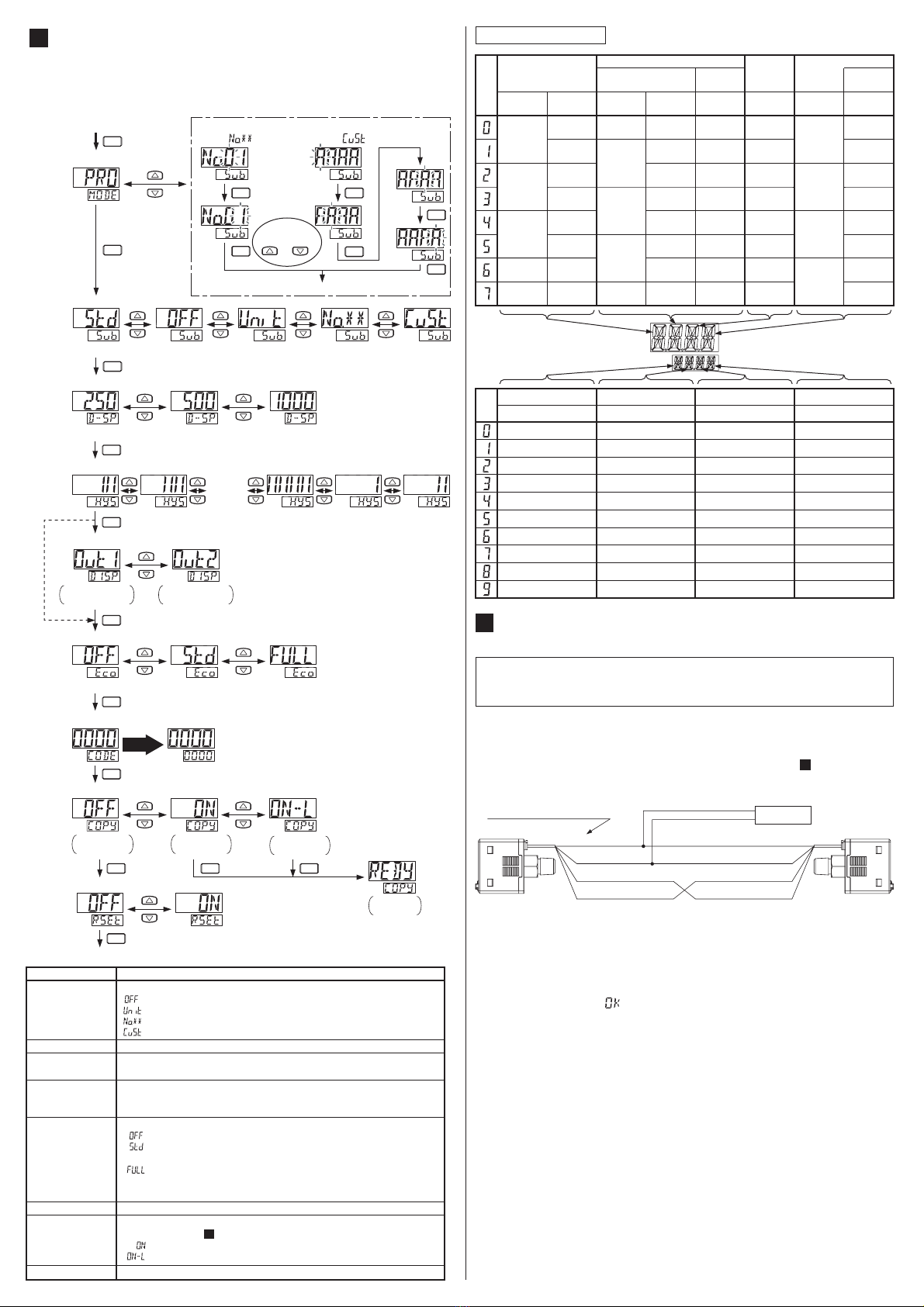
MAIN SPECIFICATIONS
14
٨Model
None: Cable with connector enclosed, J: No cable with connector
None: NPN output type, P: PNP output type
None: R
1
㧛
8
+M5 female screw, E: G
1
㧛
8
+M5 female screw, N: NPT
1
㧛
8
+M5 female screw
1: Low-pressure type, 2: High-pressure type
None: Standard type, A: High-function type
DP-10šš-š-š-š
-100 to +100 kPa -100 to +100 kPa
-0.1 to +1.0 MPa -0.1 to +1.0 MPa
-100 to +100 kPa -100 to +100 kPa
-0.1 to +1.0 MPa -0.1 to +1.0 MPa
500 kPa 500 kPa1.5 MPa 1.5 MPa
Type
Item
Pressure type
Rated pressure range
Set pressure range
Withstand pressure
Applicable fluid
Supply voltage
Gauge pressure
Non-corrosive gas
12 to 24 V DC r10% Ripple P-P 10 % or less
Power consumption
Standard type High-function type
Low-pressure typeLow-pressure type High-pressure type High-pressure type
Normal operation: 840W or less (current onsumption 35mA or less at 24V supply voltage)
ECO mode (STD): 600mW or less (current onsumption 25mA or less at 24V supply voltage)
ECO mode (FULL): 480mW or less (current onsumption 20mA or less at 24V supply voltage)
<NPN output type>
• NPN open-collector transistor
• Maximum sink current: 100mA
• Applied voltage: 30V DC or less
(between comparative output and 0V)
• Residual voltage: 2V or less
(at 100mA sink current )
<PNP output type>
• PNP open-collector transistor
•
Maximum source current: 100mA
• Applied voltage: 30V DC or less
(between comparative output and +V)
• Residual voltage: 2V or less
(at 100mA source current )
Comparative output
Output operation
Hysteresis
Selectable either N.O. or N.C., with key operation
1 digit (min.) (however, 2 digits when using psi units)
Material
±1% F.S.
(20°C reference)
2.5ms, 5ms, 10ms, 25ms, 50ms, 100ms, 250ms, 500ms, 1.000ms
or 5,000ms selectable with key operations
<High-function, low-pressure type>
• Output voltage: 1 to 5V
• Zero point: Within 3V r5%F.S.
• Span: Within 4V r5%F.S.
• Linearity: Within r1%F.S.
• Output impedance: 1kΩ approx.
<High-function NPN output type>
• ON voltage: 0.4VDC or less
•
OFF voltage: 5 to 30VDC or open
• Input impedance: 10kΩ approx.
• Input time: 1ms or more
<High-function PNP output type>
• ON voltage: 5V to +V DC
•
OFF voltage: 0.6V DC or less or open
• Input impedance: 10kΩ approx.
• Input time: 1ms or more
<
High-function, high-pressure type
>
• Output voltage: 0.6 to 5V
• Zero point: Within 1V r5%F.S.
• Span: Within 4.4V r5%F.S.
• Linearity: Within r1%F.S.
• Output impedance: 1kΩ approx.
Enclosure: PTB (with glass fiber), LCD display: Acrylic, Pressure port: Brass
(nickel-plated), Mounting screw section: Brass (nickel-plated), Switch: Silicon rubber
Analog voltage output
External input
Ambient temperature
Ambient humidity
Response time
Repeatability
Temperature characteristics
-10 to +50°C (No dew condensation or icing allowed), Storage: -10 to +60°C
35 to 85% RH, Storage: 35 to 85% RH
±0.5% F.S.
(20°C reference)
r0.1% F.S.
rwithin 2 digits
r0.2% F.S.
rwithin 2 digits
r0.1% F.S.
rwithin 2 digits
r0.2% F.S.
rwithin 2 digits
±1% F.S.
(20°C reference)
±0.5% F.S.
(20°C reference)
Weight 40g approx.(DP-100-E type: 45g approx.) (Main body only)
Accessories
CN-14A-C2 (Cable with a connector, 2m long)optional for Jtype), Unit switching label: 1 pc.
SUNX Limited
PRINTED IN JAPAN
Head Office
2431-1 Ushiyama-cho, Kasugai-shi, Aichi, 486-0901, Japan
Phone: +81-(0)568-33-7211 FAX: +81-(0)568-33-2631
Overseas Sales Dept.
Phone: +81-(0)568-33-7861 FAX: +81-(0)568-33-8591
http://www.sunx.co.jp/
WARNING
٨
٨
٨
٨
٨
٨
٨
٨
٨
٨
٨
٨
٨
٨
٨
٨
Use within the rated pressure range.
Do not apply pressure exceeding the pressure withstandability value. The
diaphragm will get damaged and correct operation shall not be maintained.
Make sure that the power supply is off while wiring.
Take care that wrong wiring will damage the sensor.
Verify that the supply voltage variation is within the rating.
If power is supplied from a commercial switching regulator, ensure that the frame
ground (F.G.) terminal of the power supply is connected to an actual ground.
In case noise generating equipment (switching regulator, inverter motor, etc.) is used in the vicini-
ty of this sensor, connect the frame ground (F.G.) terminal of the equipment to an actual ground.
Do not use during the initial transient time (0.5 sec.) after the power supply is switched on.
Do not run the wires together with high-voltage lines or power lines or put
them in the same raceway. This can cause malfunction due to induction.
The specification may not be satisfied in a strong magnetic field.
Avoid dust, dirt, and steam.
Take care that the sensor does not come in direct contact with water,
oil, grease, or organic solvents, such as, thinner, etc.
Do not insert wires, etc, into the pressure port. The diaphragm will get
damaged and correct operation shall not be maintained.
Do not operate the keys with pointed or sharp objects.
Make sure that stress by forcible bend or pulling is not applied directly to the sensor cable joint.
This is a CE conformity product complying with EMC Directive. The standard with regard to im-
munity that applies to this product is EN 61000-6-2, and in order to meet the standard, every ca-
ble connected to this product must be within 10m with 0.3mm2, or more, cable. However, in case
CE conformity is not required, the cable length can be up to 100m with 0.3mm2, or more, cable.
CAUTIONS
15
DP-100 series is designed for use with non-corrosive gas. It cannot be
used for liquid or corrosive gas.
ON
OFF
Ԙ'ԙ'P-A
Ԙ' = Ԙ㧗P-A
ԙ' = ԙ㧗P-A
Pressure
Atmospheric pressure
Output
Auto-reference input
Pressure
fluctuation
AUTO-REFERENCE FUNCTION
(ONLY HIGH-FUNCTION TYPE)
12
٨
٨
The auto-reference function corrects the setting value using the detected
pressure value during
auto-reference input as
the reference pressure.
Using the setting value P-A
as a reference, the setting
value is automatically correct-
ed to 'setting value + P-A'.
٨The setting pressure range is wider than the rating pressure range so
that the auto-reference function can be handled.
If the corrected setting value exceeds the set pressure range during auto-
reference input, the setting value will be automatically corrected to within the
set pressure range. Thus, take care not to exceed the set pressure range.
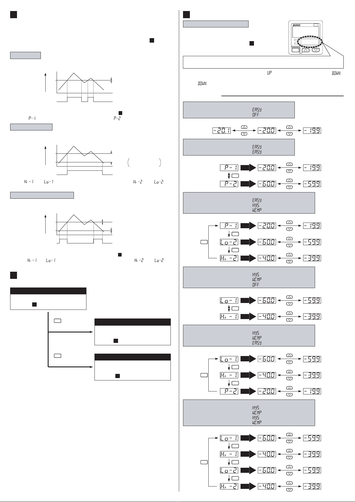
Auto-reference input: 30kPa
Output mode: Hysteresis mode
Note: The setting values shift in the same manner during the EASY mode or the win-
dow comparator mode.
٨
٨
The auto-reference input value becomes 'zero' when the setting of the analog volt-
age output / external input selection is changed or the power is turned ON again.
The auto-reference input value can be checked when setting the threshold
value in RUN mode. Refer to the threshold value setting in ' RUN MODE'
for details..
8
ON
OFF
10 20 30 40 50 60
0
10 20 30 40 50 60
0
Ԙԙ
10 20
Output
Applied pressure (kPa
)
Displayed value (kPa)
Set value (kPa)
Ԙ ԙ
40 50
P-A
30
ON
OFF
10 20 30 40 50 60
0
10 20 30 40 50 60
0
Output
Applied pressure (kPa
)
Displayed value (kPa)
Set value (kPa)
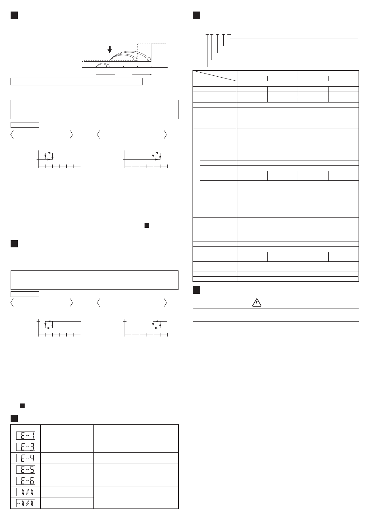
REMOTE ZERO-ADJUSTMENT FUNCTION
(HIGH-FUNCTION TYPE)
13
٨The remote zero-adjustment function forcibly sets the pressure value to
'zero' when the external signal is input.
The setting value is not corrected when remote zero-adjustment is input.
Make sure that the pressure and setting value during remote zero-adjust-
ment do not exceed the settable pressure range.
Operation chart
Operation chart
Note: The setting values shift in the same manner during the EASY mode or the win-
dow comparator mode.
٨
The remote zero-adjust input value is cleared when the setting of the analog
voltage output / external input selection is changed or the power is turned ON
again, and normal operation based on the atmospheric pressure is resumed.
The remote zero-adjustment value can be confirmed when setting the
threshold value in RUN mode. Refer to the threshold value setting in
' RUN MODE'.
8
ON
OFF
10 20 30 40 50 60
0
10 20 30 40 50 60
0
Ԙԙ
10 20
Output
Applied pressure (kPa
)
Displayed value (kPa)
Set value (kPa)
Ԙԙ
40 50
ON
OFF
10 20 30 40 50 60
0
10 20 30 40 50 60
0
Output
Applied pressure (kPa
)
Displayed value (kPa)
Set value (kPa)
Remote zero-adjustment input: 30kPa
Output mode: Hysteresis mode
Settable range and set pressure range after correction
During normal operation (each
comparative output set to N.O.)
During remote zero-adjustment input
(each comparative output set to N.O.)
During normal operation (each
comparative output set to N.O.)
During remote zero-adjustment input
(each comparative output set to N.O.)
Applied pressure range should be brought within
the rated pressure range.
Check the wiring when using the copy function.
Communication error
(Disconnection, faulty connection, etc.)
The pressure during threshold set-
ting exceeds the set pressure range.
Make sure that the system is configured of the
same models when using the copy function.
Communication error
(Incorrect model.)
Applied pressure range should be brought within
the rated pressure range.
The applied pressure exceeds the up-
per limit of the display pressure range.
The applied pressure exceeds the lower limit (re-
verse pressure) of the display pressure range.
Applied pressure at the pressure port should be brought to atmos-
pheric pressure and zero-point adjustment should be done again.
Pressure is applied during
zero-point adjustment.
Turn the power OFF and check the load.
The load is short-circuited caus-
ing an overcurrent to flow.
Error message Corrective actionCause
ERROR INDICATION
14