Mobiak DIAS User manual

FIRE SUPPRESSION SYSTEM FOR
PROFESSIONAL KITCHENS
DIAS
INSTRUCTIONS MANUAL

MVK-MAN-DIAS-REV.4, 17/09/2018
-1-

MVK-MAN-DIAS-REV.4, 17/09/2018
-2-
INTRODUCTION
In professional and domestic kitchens large quantities of cooking oils and fats are used which
are extremely flammable. The extinguishing agent used for fires from cooking oil & fats is
Wet Chemical.
Wet Chemical agent is Carboxylic Acid Salt Solution which suspends fires by creating a
saponified layer (
crust
) that prevents oxygen from interacting with the burning surface, cools
down the area and eliminates the possibilities for re-ignition. The low acidity level (PH: 9 at
20°C) prevents any damage to surfaces made of stainless steel found in Professional
Kitchens.
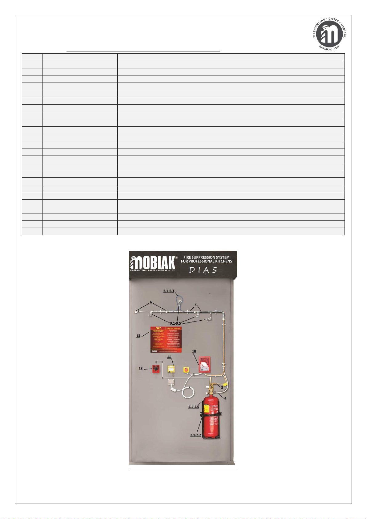
Dias Fire Detection-Suppression System is designed by MOBIAK for protecting Kitchen
Devices under Kitchen Hood, the Kitchen Hood itself and the Hood Air Ducts.
The system consists of a Wet Chemical Local Application Fire Extinguisher of both Automatic
and Manual operation, Control Panel, Fire Detection Unit and Discharge Nozzles designed for
protecting different Kitchen Devices.
Fire Detection is executed by an approved (UL/FM) Linear Heat Detection Cable (LHDC) of
138°C, 180°C or 250°C Activation Temperatures, the installation of which is particularly quick
& simple offering unique reliability & safety because it can detect fire all over the area of the
protected Kitchen Devices, Kitchen Hood and inside the Air Ducts. The LHDC is under
continuous monitoring by system’s Fire Detection-Suppression Control Panel.
In Automatic Operation, incase of Fire the Control Panel executes Alarm Signal and
simultaneously activates the System by transmitting a Signal to the fuse of the Fire
Extinguisher Valve resulting the flow of the Wet Chemical Agent through Stainless steel Tube
Network and Discharge through special type Nozzles.
In Manual Operation the system can be activated by Electrical Means by a) an Extinguish
Button that is built-in to the Control Panel or b) an System Activation Call Point that must be
installed near to the Kitchen Exit or by Mechanical Means by a) a Metal Wire Mechanism that
must be installed near to the Kitchen Exit or b) by pulling the Valve Rod of the Fire
Extinguisher Valve.
SYSTEM OPERATION
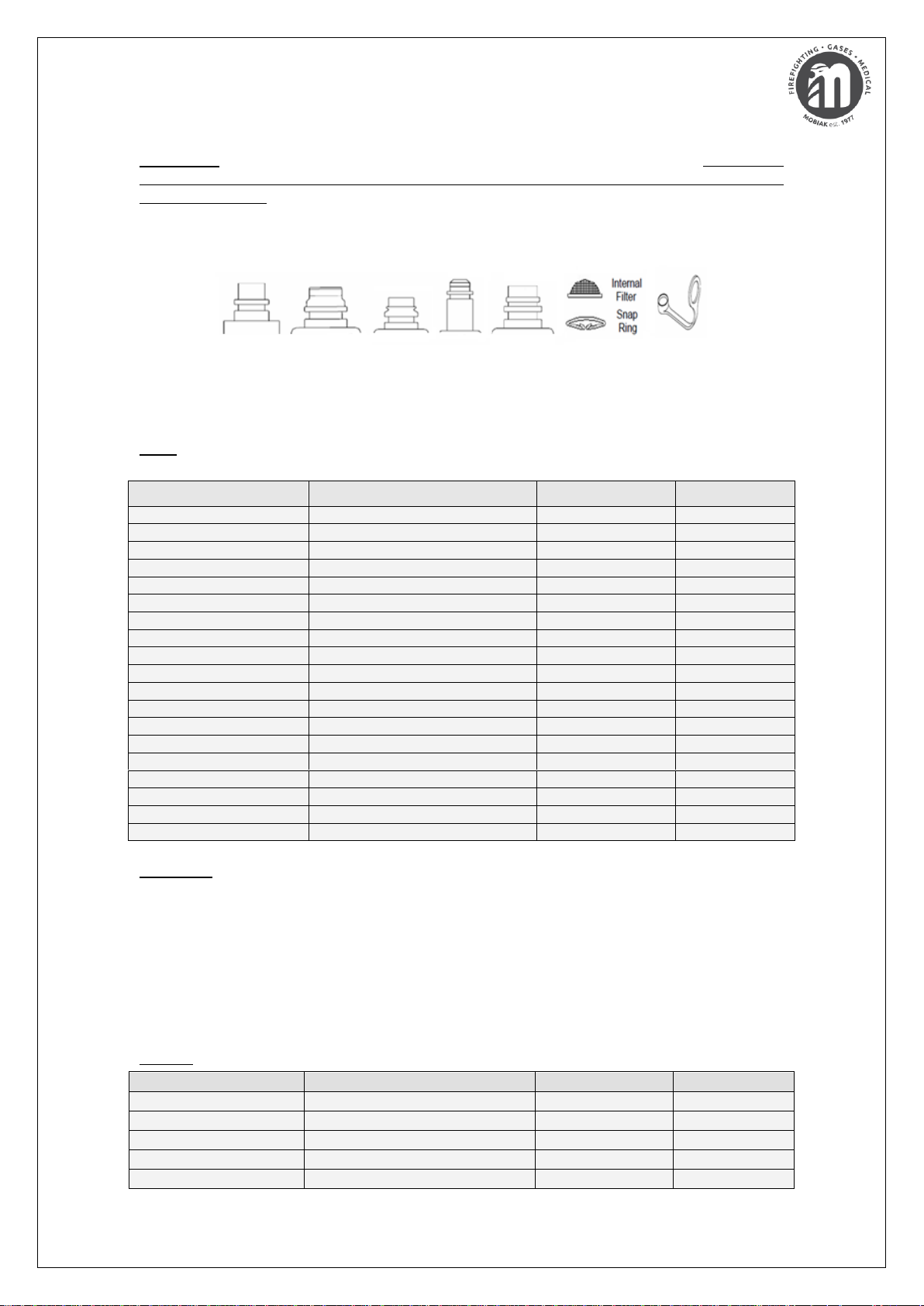
Linear Heat Detection Cable detects heat anywhere along its length. The cable is comprised
of two steel conductors individually insulated with a heat sensitive polymer. The insulated
conductors are twisted together to impose a spring pressure between them, then wrapped
with a protective tape and finished with an outer jacket suitable for the environment in which
the Detector will be installed.
Linear Heat Detection Cable is a fixed temperature sensor and is therefore capable of
initiating an alarm once its rated activation temperature is reached. At the rated temperature,
the heat sensitive polymer insulation yields to the pressure upon it, permitting the inner
conductors to move into contact with each other thereby initiating an alarm signal.
This action takes place at the first heated point anywhere along the Detector’s length. It does
not require that a specific length be heated in order to initiate an alarm nor is system
calibration necessary to compensate for changes in the installed ambient temperature. Linear
Heat Detection Cable provides the advantages of line coverage with point sensitivity.
In case of fire, during the Automatic Operation of the System, the Detection Cable is
activated and the Fire Detection-Suppression Panel executes constant Visual-Acoustic Alarm
through a built-in Siren with Beacon.

MVK-MAN-DIAS-REV.4, 17/09/2018
-3-
Note: the Control Panel used on Dias System offers the user Fuse Activation Time Delay from
0-80 seconds. This means that if the Time Delay is been configured to 40secs, Extinguisher’s
Valve Fuse Activation will take place after 40secs. Practically, this delay offers the user the
possibility to extinguish the fire using other means (
i.e. 2Lt EcoDare ABF-30C/M Portable Fire
Extinguisher or Fire Blanket
). This time delay is valid only if the system is activated
automatically (by LHDC) or in Manual Operation by Electrical Means (
described above
).
Fuse’s impact forces the valve to open and the agent starts flowing from the fire extinguisher
through a Stainless Steel Flexible Hose and Stainless steel Tube Network to Discharge Nozzles
(
of different flow rates depending on the protected device-area
), from which it is discharged
over the protected devices under the Kitchen Hood, behind Kitchen Hood Filters and inside
the Hood Air Ducts.
The discharge of the Extinguishing Agent is realized simultaneously from all the Nozzles, thus
preventing the fire transmission from area to area.
Note: Fire Detection-Suppression Control Panel has a built-in Autonomy Battery lasting a) 90
minutes fully operating and b) 72 hours in idle position, hence ensuring Automatic System
activation in case of electric power shut down in the Kitchen.
During the time delay, which may be reduced or increased by the installer (
from 0sec up to
80sec
), the user can cancel the activation of the system by pressing the Extinguish Cancel
Switch offering prevention of agent discharge incase of false alarm and time for suppressing
the fire by other means (
e.g. portable extinguisher or fire blanket
).
ZEUS Fire Detection-Suppression System may be activated manually by:
1. Extinguish Button built-in the Fire Detection Panel (electrical)
2. System Activation Call Point (electrical)
3. Pull down the fire extinguisher’s valve rod (mechanical)
4. Metal Wire Mechanism (mechanical)
Note: shut down of Electrical Power on selected Electrical Devices including the Duct fans
and of Gas/Propane Valve can be executed by an Electrical Relay built-in the Control Panel.

MVK-MAN-DIAS-REV.4, 17/09/2018
-4-
The System consists of the following Components:
1.1
MBK09-060FCS-L1C
6Ltr Fire Extinguisher of Automatic & Manual Operation
1.2
MBK09-090FCS-L1C
9Ltr Fire Extinguisher of Automatic & Manual Operation
1.3
MBK13-1016FCS-L1C
10-16Ltr Fire Extinguisher of Automatic & Manual Operation
1.4
MBK13-1720FCS-L1C
17-20Ltr Fire Extinguisher of Automatic & Manual Operation with Heavy Duty Bracket
1.5
MBK13-2135FCS-L1C
21-35Ltr Fire Extinguisher of Automatic & Manual Operation with Heavy Duty Bracket
2.1
MBK13-HDBRACKET-6
Heavy Duty Fire Extinguisher Bracket For 6Ltr Fire Extinguisher
2.2
MBK13-HDBRACKET-12
Heavy Duty Fire Extinguisher Bracket For 9Ltr & 10-16Ltr Fire Extinguisher
3
MBK02-PYR
Fuse used for Automatic Activation of the Extinguisher’s Valve
4
MBK13-SSTUBE-1/2
Stainless Steel Flexible Hose used for connecting Cylinder’s Valve with the Pipe Network
5.1
MBK12-WIRE-138
Linear Heat Detection Cable 138°C
5.2
MBK12-WIRE-180
Linear Heat Detection Cable 180°C
5.3
MBK12-WIRE-250
Linear Heat Detection Cable 250°C
6
MBK12-CLEMA
Porcelain Splice Connectors used for Linear Heat Detection Cable Connections
7
MBK12-DEMATIKO
Stainless Steel Straps used for Linear Heat Detection Cable Support
8
MBK12-FIRETAPE
Fire Tape used for Linear Heat Detection Cable Connections Insulation
9.1
MBK13-NOZZLE-A2
A2 Discharge Nozzle with Silicon Cap
9.2
MBK13-NOZZLE-A3
A3 Discharge Nozzle with Silicon Cap
9.3
MBK13-NOZZLE-A4
A4 Discharge Nozzle with Silicon Cap
9.4
MBK13-NOZZLE-A8
A8 Discharge Nozzle with Silicon Cap
9.5
MBK13-NOZZLE-A9
A9 Discharge Nozzle with Silicon Cap
10
MBK12-ZEUS-PANEL
Fire Detection-Suppression Panel with Battery including Extinguish Button, Siren with
Beacon, Relay for Electrical Power Shut down & Extinguish Cancel Switch
11
BS-534
System Activation Call Point (electrical)
12
MBK13-ACTIV-WIRE
System Activation Metal Wire Mechanism (mechanical)
13
MBK13-DIAS-INS
Usage Instructions Sign –For installation in Kitchen

MVK-MAN-DIAS-REV.4, 17/09/2018
-5-
Important: The System consists of specific Components approved by MOBIAK. Any change
on the components given on this Manual is forbidden by the manufacturer as it will affect
system’s operation.
The Discharge Nozzles (½” Male Thread) are made of Stainless Steel and come with white
colour incombustible Silicon Protection Cap.
There are available five (5) nozzles of different flow rates A2 (1 Flow Unit), A3 (1.5 Flow
Unit), A4 (1.5 Flow Unit), A8 (2 Flow Units) and A9 (2 Flow Units) discharging the
extinguishing agent in mist propagation form (use of Internal Filter mounted by Metal Snap
Ring).
Note: Each nozzle is designed so that to protect kitchen devices/appliances according to the
following table –Engineers must choose the Nozzles strictly according the following
Device
Max Dimension
Disch. Nozzles
Flow Units
Air Duct
122cm Diameter/381 Perimeter
3pcs-A3
4,5
Air Duct
81cm Diameter/254 Perimeter
2pcs-A3
3
Air Duct
41cm Diameter/127cm Perimeter
1pcs-A3
1,5
Air Duct
61cm Diam/190cm Perim
1pcs-A9
2
Exhaust Hood
305cm Length
1pcs-A2
1
Deep Fryer
(48 x 64) cm
1pcs-A9
2
Cooking Plate
(76 x 122) cm
1pcs-A8
2
Cooking Plate
(76 x 107) cm
1pcs-A9
2
Cooking Plate
(76 x 91) cm
1pcs-A2
1
Electrical Oven
(31 x 61) cm
1pcs-A2
1
Electrical Oven
(61 x 61) cm
1pcs-A8
2
Oven
(72 x 72) cm
2pcs-A4
1,5
Electrical Grill
(52 x 61) cm
1pcs-A2
1
Propane/Gas Grill
(52 x 61) cm
1pcs-A2
1
Ceramic Grill
(52 x 61) cm
1pcs-A2
1
Deep Frying Pan
(35 x 61) cm
1pcs-A2
1
Grill-Charcoal
(61 x 72) cm
1pcs-A3
1,5
Grill-Wood
(61 x 72) cm
1pcs-A3
1,5
Kebab Device
(78 x 73) cm
2pcs-A4
1,5
EXAMPLE
In a Professional Kitchen there are there is the following equipment:
One (1) Air duct: 81cm diameter
One (1) Kitchen Hood: 305cm length
One (1) Deep Fryer: (48x64)cm
One (1) Cooking Plate: (76x122)cm
One (1) Oven: (72x72)cm
One (1) Deep Frying Pan: (35x61)cm
One (1) Grill-Charcoal: (61x72)cm
STEP.1: According to the Kitchen Equipment the Type & Number of Nozzles are the following
Device
Max. dimensions
Disch. Nozzles
Flow Units
Air Duct
81cm diameter
2pcs-A3
3
Kitchen Hood
305cm length
1pcs-A2
1
Deep Fryer
(48 x 64)cm
1pcs-A9
2
Cooking Plate
(76 x 122)cm
1pcs-A8
2
Oven
(72 x 72)cm
2pcs-A4
1,5

MVK-MAN-DIAS-REV.4, 17/09/2018
-6-
Deep Frying Pan
(35 x 61)cm
1pcs-A2
1
Grill-Charcoal
(61 x 72)cm
1pcs-A3
1,5
STEP.2: The Sum of Flow Units Sum of the selected nozzles is
Flow Units Sum: 3 + 1 + 2 + 2 + 1,5 + 1 + 1,5 = 12 Flow Units
STEP.3: Divide the sum of flow units with the constant number 0.8 so that to calculate the
Quantity of the Extinguishing Agent:
Extinguishing Agent Quantity: 12 / 0.8 = 15ltr
STEP.4: Choose the fire extinguisher of the system according to the calculated Agent
quantity:
Extinguisher Type: 10-16Ltr Fire Extinguisher filled with 15Ltr Extinguish Agent
Note: the quantity of the extinguishing agent always depends on the selected discharge
nozzles.
TOTAL FLOODING
STEP 1: Calculate the number of nozzles with Code Name A8 of the Exhaust Gas Coefficient
by dividing the Load Length by 50cm (as the required distance between the Sprinklers is).
Always deduct 30cm from the Total length of each end:
Number of Sprinklers A8: (305cm - 60cm) / 50cm: 4.9pcs (≈5pcs)
* In case of decimal then round it to the next integer.
STEP 2: Calculate the Type & Number of Nozzles in the Air Ducts and Filter Gap:
Protection Area
Max. Dimensions
Nozzles
Flow units
Air Duct
81cm (dia.)
2pcs-A3
3
Hood
305cm (length)
1pc-A2
1
STEP 3: Then calculate the Sum of Flow Units based on the above table (step 2) and the
total A8 ejector pieces (step 1):
Flow Unit Sum: = (5pcs A8 x 2) + 3 + 1 = 14 Flow Units
STEP 4: To find the amount of Extinguishing Material divide the sum of the Flow Units by the
Fixed Coefficient of 0.8, that is:
Amount of Extinguishing Material: 14 / 0.8 = 17.5ltr
STEP 5: Select the System Fire Extinguisher which in this case should be 20ltr.
Type of Fire Extinguisher: 19.5Ltr Container with 17.5Ltr Extinguishing Material
CONCLUSION: In this example, the required amount of fire extinguishing material for Local
Application is 15ltr, while for Total Flooding it is 17.5ltr. This difference arises from the fact
that in a Total Flooding System, all of the space under the Exhaust Hose is protected as one
device by the A8 (Maximum Coverage-Protection) nozzle while in a Local Application System
each appliance is protected locally under the Exhaust Hood with the choice of a nozzle
according to its type and size.
HYDRAULIC PIPE NETWORK
Stainless Steel Flexible Hose, Stainless Steel tubes (φ18) and Stainless Steel Components as
nipples, 90° corners and tee pieces consists the Hydraulic Pipe Network of ZEUS System that
leads the extinguishing agent from the fire extinguisher to the nozzles from where it is
discharged.

MVK-MAN-DIAS-REV.4, 17/09/2018
-7-
Installation starts with the mounting of the fire extinguisher on to the heavy duty bracket.
The fire extinguisher must be installed into an Easy-Access-Point inside the Kitchen in a safe
distance from heat surfaces while the room temperature should not exceed the 60oC.
Flexible Stainless Steel Hose (
female thread at both ends
) is used for the connection of the
Extinguisher Valve Outlet with the Hydraulic Pipe Network.
Soft Bearing is used for the construction of the Hydraulic Network - soft bearing must be
according the following specifications
Freezing Point
Melting Point
Colour
Elogation
Durability
238˚C
332˚C
Silver
48%
6600–7400psi
Note: The Pipe Network must not exceed nine (9) meters length
Discharge Nozzles must be installed at 1-1.2m height above Kitchen Devices, behind Kitchen
Hood Filters and inside the Kitchen Hood Air Ducts, as described in previous table.
Note 2: A2 Discharge Nozzle can protect up to 305cm Exhaust Hood Length - if the Kitchen
Hood is longer than 305cm the number of A2 Nozzles must be calculated accordingly.
The Discharge Nozzles protecting of the Air Ducts of the Exhaust Hood must be installed at
20cm depth inside each Air Duct.
The Silicone Protection Cap of the Discharge Nozzles must never be removed because it
prevents moisture, vapors, grease and other particles getting & stuck on the small hole from
where the agent is been discharged.
Note 3: Stainless Steel Tubes and Components required for the construction of the System’s
Pipe Network are not traded by MOBIAK and must be supplied from local market.
LINEAR HEAT DETECTION CABLE
Linear Heat Detection Cable is a fixed temperature sensor of activation temperatures 138°C,
180°C or 250°C. The selection of Activation Temperature of the Linear Heat Detection Cable
in each kitchen must be performed after Temperature Measurement (
preferably digitally
) at
1-1.2m height above the under protection Kitchen Devices when the kitchen is in full
operation.
Practically, the Installation of the Cable is Simple & Fast procedure as the Cable is mounted
by Stainless Steel Straps (Fasteners) on the Stainless Steel Tubes of the Hydraulic Network of
the System.
Fasteners should typically be spaced every 1-1.5m or as may be necessary to prevent the
wire from excessive sagging which puts undue stress on the wire at the fastening points.
Improper installation and fastening may also subject the Detector to physical damage.
Note: Fasteners which are over-tightened apply excess stress that will eventually cause
insulation damage to the Detector resulting in unwanted alarms.
Important Installation Instructions
Do not over tighten the fasteners as this may breach the outer jacket or crush the inner
insulation, causing unwanted alarms. All fasteners must allow the wire to expand and
contract with temperature changes.
Do not over stretch the Cable during installation - some wire “sag” between fasteners is
normal.

MVK-MAN-DIAS-REV.4, 17/09/2018
-8-
Do not make 90° bends in the detector.
Do not hold the wire with pliers to make bends. All bends should be made with the
fingers and consist of rounded turns with a minimum 6.4 cm radius.
Do not use wire nuts or other similar devices. All connections must be made via
MOBIAK’s porcelain splicing connectors.
Do not paint this detector, per UL and FM requirements.
Porcelain Splice Connectors of two (2) contacts used to connect Cables of different activation
temperatures. The connection is based on the following steps.
Step.1: Remove insulation from each wire leaving 1/2” (1.3cm) of bare Linear Heat Detector
conductor, preserving 3/8” (.9cm) of insulation from bare wire back to the covering.
Step.2: Install wires as shown below making sure the entire 1/2” (1.3cm) portion of bare
Linear Heat Detector conductor is embedded in splicing connector.
Step.3: Secure Linear Heat Detector by tightening the connector screws. Plastic screw
Step 3: Secure Linear Heat Detector by tightening the connector screws. Plastic screw
turrets may be trimmed with snips or utility knife for easier taping.
Step.4: Using 10.1cm-12.7cm of Electrical Tape wrap the splice. Stretch and overlap each
wrap of tape.
The installer must ensure proper connections and conductors proper insulation (
by special
Fire Tape
) - in case that the conductor is not properly insulated during contact with metal
surface (
e.g. exhaust hood surface
) there will be triggered false alarm signal.
There is continuous monitoring of Linear Heat Detection Cable (
from Control panel
) which
ensures notification to the end user when cutting or disconnection.
The Detection Cable is been monitored by Control Panel by an Electric Resistor 2.2ΚΩ at the
end of the detection line (
outside the exhaust hood
).
Note: installer must ensure that the Cable runs continuous –branches are forbidden because
monitoring of the branch from the Control Panel will no longer exist.
Installer must ensure that Linear Heat Detection Cable adequately covers the whole area
under the Kitchen Hood (
over Kitchen Devices
) and inside the Kitchen Hood Air Ducts.

MVK-MAN-DIAS-REV.4, 17/09/2018
-9-
Great advantages of Linear Heat Detection Cable compared to other Pneumatic Heat
Detection Cables are indicated on the following table
Description
ΜΟΒΙΑΚ’s Cable
Pneumatic Cables
Different Activation Temperatures
YES
NO
Cable Part replacement
YES
NO
Detection Device without Pressure
YES
NO
Maintenance Free
YES
NO
System Free from Moving Parts
YES
NO
Extinguish Time delay Option
YES
NO
The detection cable is not under pressure, and as a result the possibilities for alterations due
to temperature changes in the Kitchen Hood are minimized.
As indicated on the above table, ZEUS system offers the end user System Activation Time
Delay Option (
which cannot exist in systems using Pneumatic Detection Tubes-Wires
).
This option is critical for the end user because it offers System Activation Cancel Option
incase of a) false alarm and b) killing the fire with other means (
e.g. Portable EcoDare ABF-
30C/M Extinguishers, Fireproof Blanket
).
FIRE DETECTION-SUPPRESSION PANEL
MOB-2001 is a Fire Detection-Suppression Panel that incorporates Siren with Beacon,
Extinguish Button, Extinguish Cancel Switch, built-in Battery & Electrical Relay for shut down
the Power Supply of Electrical Devices, Duct Fans as well as the Gas Valve.
The connections on the Panel are easy, fast and take place outside the Panel (factory made
external wiring
). The Linear Heat Detection Cable must be connected to the Splicing
Connector of the Orange Cable (
as shown in following pictogram
).
Note: in case of problem on the Detection Line (
e.g. damaged cable or not proper
connection)
MOB-2001 sounds customized alarm signal warning the user about the problem
on the system’s Detection Line.
Extinguish Cancel Switch is been factory-connected to MOB-2001 by a 2m length cable (
as
shown in following pictogram
).
Fuse of the Fire Extinguisher Valve must be connected to the Splicing Connector of the White
Cable of the Fire Detection Panel (
as shown in following pictogram
)
MOB-2001 is been factory connected to Suko Plug so that to be directly connected to a usual
plug of the kitchen (
as shown in following pictogram
)

MVK-MAN-DIAS-REV.4, 17/09/2018
-10-
Note: Fire Detection-Suppression Panel MOB-2001 is compatible only with the Linear Heat
Detection Cable supplied by MOBIAK.
Panel LEDs (Green, Yellow & Red) are used for indicating Panel’s Battery Status, Alarm Status
and Fuse Proper Connection ensuring the Proper Operation of the System.
Important: the Control Panel must be installed on a stable position at least three (3) meters
away from the warm surfaces of the kitchen.
SYSTEM INSPECTION
Visual Inspection of the System is recommended once per month by Kitchen Owner or
Personnel.
Note: Inspection is possible to be performed from the Kitchen Owner or Personnel only in
case the training has successfully been completed by MOBIAK or any of its Authorized System
Integrators.
The procedures are the following:
Visual check of the System’s Manual Triggering Mechanisms (
Fire Extinguisher Valve Rod,
Metal Wire Mechanism, System Activation Call Point
), which should be always in reach
with ease and without any obstacles in front.
Visual check of Linear Heat Detection Cable for defects.
Visual check of the Fire Detection-Suppression Panel operational status (
indication LED’s
)
Visual check of the Fire Extinguisher Pressure Gauge so that to secure correct pressure
indication which must always be inside the green area at 15Bar WP
Check the Expiry Date of Fuse
Check the Discharge Nozzles –the protective caps must always be in position and not
damaged
General check on the Hydraulic Network for possible damages which may lead to leakage.
Check of the Stainless Steel Flexible Hose in order to secure that there are no defects or
damage.
Check of the predefined Inspection Date of the Fire Extinguisher
If case of damage on any System Component identified during Inspection the Owner or the
Personnel of the Kitchen must immediately contact Authorized Maintenance Technicians
properly qualified and trained by MOBIAK or by MOBIAK’s Authorized System Integrators.

MVK-MAN-DIAS-REV.4, 17/09/2018
-11-
Upon the completion of the Inspection, the Owner or Personnel of the Kitchen executed the
procedure must always fill in the Maintenance Form stating clearly the actions took place.
Inspection Forms should always be completed at the end of each inspection and is mandatory
to include information such as the Full Details (
Name-Surname-Position
) of the person
executed Inspection as well as the Inspection Date.
IMPORTANT: Inspection Forms should not be destroyed and is the Kitchen Owner’s
responsibility to keep them in a safe location.
SYSTEM SERVICE/MAINTENANCE
System’s maintenance must be always performed only by Authorized Maintenance
Technicians properly qualified and trained by MOBIAK or by any of MOBIAK’s Authorized
System Integrators.
Note: Maintenance Technicians can be trained by owners of Fire Fighting Equipment Stores
only in case that the owner holds a Training Certificate on the Fire Suppression System issued
only by MOBIAK.
Maintenance Technicians should always have the System’s Manual in order to be able to
perform the predefined maintenance once (1) a year (minimum), as follows:
Maintenance of the Local Application Fire Extinguisher according European Guidelines &
Regulations for maintenance of low pressure fire extinguishers.
Operational Check & Maintenance of Linear Heat Detection Cable which must be gently
cleaned with a wet table cloth (use of clean water) so that to remove grease or fat.
Replacement of the Fire Tape used for insulating the connections of the Linear Heat
Detection Cable on the Connections
Operational Check & Maintenance of System’s Fire Detection-Suppression Panel according
to Manufacturer’s Manual.
Replacement of Fire Detection-Suppression Panel battery every five (5) years, according
to Manufacturer’s Manual.
Check the Expiry Date of the Fuse - replacement of the fuse if necessary based on the
expiry date.
Check for damages on the Electrical Wires and Connection Points and replacement if
necessary.
Check the White Silicon Caps of the Nozzles which must be replaced in case of defects.
In case of System Activation and Agent Discharge, cleaning of the Stainless Steel Pipe
Network with water must take place in order to make sure the proper operation of the
system next time - the water must be connected to the Stainless Steel Flexible Hose and
will be discharged from the Nozzles –this procedure must last 10 minutes for proper
cleaning).
Important: during maintenance the Extinguish Cancel Switch should be activated so that to
avoid accidental system activation.
In case of damaged or faulty components, these must be immediately replaced only with new
Components listed on this manual.
Important: Any change on the components given on this Manual is forbidden by the
manufacturer as it will affect system’s operation.
Prior the beginning of maintenance and replacement of damaged components the Owner and
Personnel of the Kitchen must be informed as the System will immediately declared as Non

MVK-MAN-DIAS-REV.4, 17/09/2018
-12-
Functional until all necessary works have been carried out and the System has been fully
returned to its original Functional Status.
Note: Maintenance Form must be filled in only when the Owner or a Representative of the
Owner is present.
Maintenance documents must be kept on a file-form. These documents must never be
damaged.
IMPORTANT: After system’s maintenance, the technician must place a maintenance label in
the kitchen on which it must be visible the date of maintenance as well as the full-name of
the technician who executed the maintenance.
SYSTEM REFILLING
The local application Fire Extinguisher of the Fire Suppression System should always be
refilled exclusively with Wet Chemical Agent approved by MOBIAK, in any of the following
cases:
Immediately after five (5) years from the production date of the Fire Extinguisher,
according to European Regulation guidelines.
Immediately after it is used from as a result of the System’s activation in case of fire.
Note: the Pressure of the Local Application Fire Extinguisher must always be at 15 Bar.
The hydraulic test of the cylinder of the system’s fire extinguisher of the system must be
executed once after 10 years.

MVK-MAN-DIAS-REV.4, 17/09/2018
-13-
INSPECTION FORM
Α/Α
DATE
TECHNICIAN FULL NAME
DESCRIPTION OF SERVICES
SIGNATURE
01
02
03
04
05
06
07
08
09
10
11
12

MVK-MAN-DIAS-REV.4, 17/09/2018
-14-
MAINTENANCE FORM
Α/Α
DATE
TECHNICIAN FULL NAME
DESCRIPTION OF SERVICES
SIGNATURE
01
02
03
04
05
06
07
08
09
10
11
12
Table of contents
Other Mobiak Medical Equipment manuals