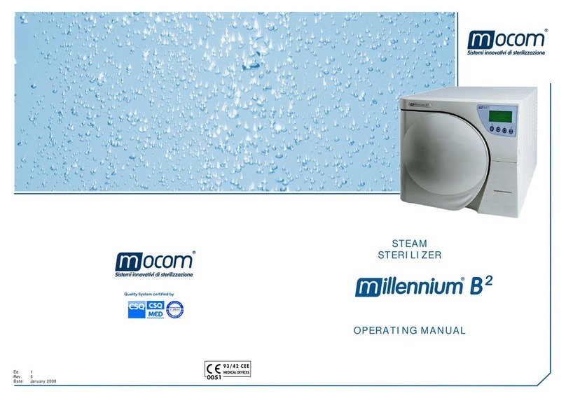
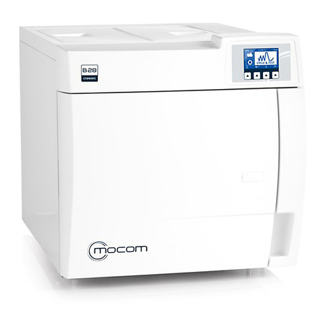
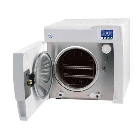
Mocom B FUTURA User manual

CEFLA S.C. Via Selice Prov.le 23/A - 40026 Imola (BO)
After Sales Service
tel. +39 0542 653566 -
Fax +39 0542 653596
E-mail: service.sterilization@cea.it
B FUTURA
B CLASSIC
S CLASSIC
Technical manual
code 97071170 rev. 02


1
EN
TECHNICAL MANUAL - B CLASSIC / B FUTURA / S CLASSIC
CONTENTS
CONTENTS
1. FUNCTIONING.............................................................................................................................................................................3
1.1 STANDBY.............................................................................................................................................................................3
1.2 WARM-UP ............................................................................................................................................................................4
1.3 1st VACUUM PHASE ...........................................................................................................................................................5
1.4 1st PRESSURE RISE...........................................................................................................................................................6
1.5 2nd VACUUM PHASE ..........................................................................................................................................................7
1.6 2nd PRESSURE RISE .........................................................................................................................................................8
1.7 3rd VACUUM PHASE...........................................................................................................................................................9
1.8 3rd PRESSURE RISE / STERILISATION PROCESS........................................................................................................10
1.9 DISCHARGE ......................................................................................................................................................................12
1.10 DRYING..............................................................................................................................................................................13
1.11 VENTILATION ....................................................................................................................................................................14
1.12 PRESSURE LEVELLING ...................................................................................................................................................15
2. ALARMS .............................................................................................................................................................................16
2.1 ERROR ALARMS - CODE “E”............................................................................................................................................16
2.2 FAULT ALARMS - CODE “A”..............................................................................................................................................16
2.3 HAZARD ALARMS - CODE “H”..........................................................................................................................................18
2.4 ACCESSORY ALARMS - CODE “S” ..................................................................................................................................18
2.5 LCD E INDICATIONS .........................................................................................................................................................19
2.6 LCD A INDICATIONS .........................................................................................................................................................25
2.7 LCD H INDICATIONS.........................................................................................................................................................34
2.8 LCD S INDICATIONS .........................................................................................................................................................38
3. SYSTEM RESET ........................................................................................................................................................................42
3.1 FUTURA SYSTEM RESET ................................................................................................................................................42
3.2 CLASSIC SYSTEM RESET ...............................................................................................................................................43
4. SERVICE MENU.........................................................................................................................................................................44
5. TECHNICAL DATASHEET.........................................................................................................................................................75
5.1 TECHNICAL DATASHEET ST01 - STEAM GENERATOR.................................................................................................75
5.2 TECHNICAL DATASHEET ST02 - MANIFOLD..................................................................................................................78
5.3 TECHNICAL DATASHEET ST03 - DOOR GEARMOTOR ASSEMBLY .............................................................................80
5.4 TECHNICAL DATASHEET ST04 - PRESSURE TRANSDUCER - SAFETY PRESSURE SWITCH..................................81
5.5 TECHNICAL DATASHEET ST05 - PT1 SENSOR - CHAMBER TEMPERATURE SENSOR ............................................83
5.6 TECHNICAL DATASHEET ST02 – DOOR ADJUSTMENT................................................................................................84
5.7 FIRMWARE UPDATE.........................................................................................................................................................86
6. NETWORK CONNECTION - USER INTERFACE......................................................................................................................89

2EN
B CLASSIC / B FUTURA / S CLASSIC - TECHNICAL MANUAL
CONTENTS

3
EN
TECHNICAL MANUAL - B CLASSIC / B FUTURA / S CLASSIC
FUNCTIONING
1. FUNCTIONING
1.1 STANDBY
Upon power-on, the autoclave goes into STANDBY mode. User-selectable standby options are as follows:
- STANDBY OFF
- STANDBY ON
In the STANDBY OFF mode, the following components are powered off:
- solenoid valves;
- fans;
- water pump;
- vacuum pump.
The following components are not turned on:
- chamber band heater;
- generator heating element.
In the STAND BY mode the chamber heater is powered on and controlled by a heat controller that maintains:
- chamber temperature at 50°C with the door open
- chamber temperature at 100°C with the door closed
On STAND BY ON mode and door closed solenoid valve EV5 is activated.
STAND BY - components on state
STATE
EV1
Drain
High (NO)
EV2
Air inlet
(NC)
EV3
Drain Low
(NC)
EV4
Drain
bypass
(3V)
EV5
Air inlet to
chamber
(NC)
FAN
WATER
PUMP
VACUUM
PUMP
CHAMBER
BUNDLE HTR
GENERATOR
HTNG ELMT
OFF
Off
open
Off
closed
Off
closed
Off (0)
Off
closed
OFF OFF OFF OFF OFF
ON
door open
Off
open
Off
closed
Off
closed
Off (0)
Off
closed
OFF OFF OFF ON OFF
ON
door
closed
Off
open
Off
closed
Off
closed
Off (0)
On
open
OFF OFF OFF ON OFF

4EN
B CLASSIC / B FUTURA / S CLASSIC - TECHNICAL MANUAL
FUNCTIONING
1.2 WARM-UP
When the door is closed, if one of the 6 available sterilization cycles is selected and activated, the door is locked and
the WARM-UP phase is activated.
During this phase are warmed up:
- chamber by the chamber heating element;
- generator by the generator heating element;
until reaching the following temperature levels.
- tube bundle heating element > PT3 temperature reading - 110°C;
- generator heating element > PT2 temperature reading - 140°C;
- chamber > PT1 temperature reading - 60°C.
When the above values are reached, the next phase begins. This is the 1st VACUUM PHASE.
The 1st VACUUM PHASE will start after 10 minutes even though the temperature readings are below the values listed
above.
The WARM-UP phase is divided into 2 sections:
- section 1 continues until PT2 temperature reading = 110°C
- section 2 continues until PT2 temperature reading = 140°C
During section 2 of the WARM-UP phase, the following components are turned on:
- vacuum pump
- solenoid valve EV2 (air suction)
- solenoid valve EV4 (vacuum pump bypass)
so that the pump reaches its regular operating conditions and any condensate in the tubes is eliminated.
WARM-UP - components on state
STATE
EV1
Drain
High (NO)
EV2
Air inlet
(NC)
EV3
Drain Low
(NC)
EV4
Drain
bypass
(3V)
EV5
Air inlet to
chamber
(NC)
FAN
WATER
PUMP
VACUUM
PUMP
CHAMBER
BUNDLE HTR
GENERATOR
HTNG ELMT
Section
1
On
closed
Off
closed
Off
closed
Off (0)
On
open
OFF OFF OFF ON ON
Section
2
Off
open
On
open
Off
closed
On (1)
Off
closed
ON OFF ON ON OFF

5
EN
TECHNICAL MANUAL - B CLASSIC / B FUTURA / S CLASSIC
FUNCTIONING
1.3 1st VACUUM PHASE
This phase marks the beginning of the sterilization cycle proper. As the vacuum pump is activated, the maximum
vacuum level in the chamber, namely – 0.80 bar, can be reached (S 17 Classic -0.75 bar).
The tube bundle heating element of the chamber and the generator heating element remain activated throughout this
phase so the steam generation can be managed properly.
The 1st VACUUM PHASE must ensure that as much air as possible is removed from the chamber. In order to achieve
this, repeated steam shots are injected as pressure drops to aid removal of any remaining air.
These steam shots are operated automatically according to pressure value in the chamber as follows:
- steam shot starts > chamber pressure reading – 0.70
- steam shot ends > chamber pressure reading – 0.60
This sequence is repeated 3 times, and pressure drops until reaching the preset vacuum level of – 0.80 bar. This value
triggers the next phase, namely the 1st PRESSURE RISE.
The control system operates the solenoid valve EV2 (air inlet) when it is needed to improve vacuum pump perfor-
mance, which may be the case during the last pressure drop phase.
1st VACUUM PHASE - components on state
STATE
EV1
Drain
High (NO)
EV2
Air inlet
(NC)
EV3
Drain Low
(NC)
EV4
Drain
bypass
(3V)
EV5
Air inlet to
chamber
(NC)
FAN
WATER
PUMP
VACUUM
PUMP
CHAMBER
BUNDLE HTR
GENERATOR
HTNG ELMT
Drop
to
vacuum
On
closed
Off
closed
On
open
On (1)
Off
closed
ON OFF ON ON ON
Steam
shot
Off
open
Off
closed
Off
closed
On (1)
Off
closed
ON ON ON ON ON
A preset minimum pressure value can be reached during the vacuum pulses; this value varies with each vacuum pump
type installed on the autoclaves.
VACUUM PUMP PMIN [bar]
Type H5 -0.75
Type H5P3 -0.80
Type EVO10 -0.80
Type EVO30 -0.80

6EN
B CLASSIC / B FUTURA / S CLASSIC - TECHNICAL MANUAL
FUNCTIONING
1.4 1st PRESSURE RISE
During this phase, steam injection into the chamber is activated to raise pressure back up to 1.00 bar from the negative
value reached during the vacuum pulse.
Pressure is raised in two steps; rstly, from – 0.80 bar to 0.00 bar, and then from 0.00 bar to 1.00 bar.
During the rst pressure rise step, solenoid valve EV2 is activated to compensate for any air pockets which may have
developed in the hydraulic circuit outside the chamber.
The tube bundle heating element of the chamber and the generator heating element remain activated throughout the
pressure rise phase to ensure that the proper temperature is maintained in the chamber and enable fast steam genera-
tion.
1st PRESSURE RISE - components on state
STATE
EV1
Drain
High (NO)
EV2
Air inlet
(NC)
EV3
Drain Low
(NC)
EV4
Drain
bypass
(3V)
EV5
Air inlet to
chamber
(NC)
FAN
WATER
PUMP
VACUUM
PUMP
CHAMBER
BUNDLE HTR
GENERATOR
HTNG ELMT
Step 1
from
- 0.80 to
0.00
Off
open
On
open
Off
closed
On (1)
Off
closed
ON ON OFF ON ON
Step 2
from 0.00
to 1.00
Off
open
Off
closed
Off
closed
Off (2)
Off
closed
ON ON OFF ON ON
After the 1st PRESSURE RISE is completed properly, the sterilization cycle continues as pressure is lowered again to
the same negative value as during the 1st VACUUM PHASE during two additional VACUUM PHASES, which are sepa-
rated by a second PRESSURE RISE up to 1.00 bar.

7
EN
TECHNICAL MANUAL - B CLASSIC / B FUTURA / S CLASSIC
FUNCTIONING
1.5 2nd VACUUM PHASE
During this phase of the cycle, the pressure in the chamber, which had reached 1.00 bar during the 1st PRESSURE
RISE is lowered by releasing steam through solenoid valve EV1 and the condensate fraction through solenoid valve
EV3, which is connected to the chamber lter.
Upon reaching 0.10 bar, solenoid valve EV4 is activated and has the vacuum pump – which had been activated at the
beginning of the 2nd VACUUM PHASE – lower pressure further to approach – 0.80 bar.
No steam shots occur during this phase.
2nd VACUUM PHASE - components on state
STATE
EV1
Drain
High (NO)
EV2
Air inlet
(NC)
EV3
Drain Low
(NC)
EV4
Drain
bypass
(3V)
EV5
Air inlet to
chamber
(NC)
FAN
WATER
PUMP
VACUUM
PUMP
CHAMBER
BUNDLE HTR
GENERATOR
HTNG ELMT
Direct
steam
discharge
Off
open
Off
closed
Off
closed
Off (2)
Off
closed
ON OFF ON ON ON
Direct
condensate
discharge
On
closed
Off
closed
On
open
Off (2)
Off
closed
ON ON OFF ON ON
Pressure
drops
from 0.10
to -0.80
bar
On
closed
Off
closed
On
open
On (1)
Off
closed
ON ON OFF ON ON

8EN
B CLASSIC / B FUTURA / S CLASSIC - TECHNICAL MANUAL
FUNCTIONING
1.6 2nd PRESSURE RISE
This phase is similar to the 1st PRESSURE RISE, in that pressure rises back up to 1.00 bar from the negative value
reached during the vacuum pulse.
The sequence of vacuum pulses and pressure rise phases eliminates nearly all air left inside the sterilization chamber,
as well as any air contained in any hollow bodies or porous materials included in the load.
Eliminating air ensures optimal steam diffusion and equal temperature at all points of the load.
2nd PRESSURE RISE - components on state
STATE
EV1
Drain
High (NO)
EV2
Air inlet
(NC)
EV3
Drain Low
(NC)
EV4
Drain
bypass
(3V)
EV5
Air inlet to
chamber
(NC)
FAN
WATER
PUMP
VACUUM
PUMP
CHAMBER
BUNDLE HTR
GENERATOR
HTNG ELMT
Step 1
from -
0.80 to
0.00
Off
open
On
open
Off
closed
On (1)
Off
closed
ON ON OFF ON ON
Step 2
from 0.00
to 1.00
Off
open
Off
closed
Off
closed
Off (2)
Off
closed
ON ON OFF ON ON
After this phase, the 3rd VACUUM PHASE is carried out in the same mode used for the 2nd VACUUM PHASE.

9
EN
TECHNICAL MANUAL - B CLASSIC / B FUTURA / S CLASSIC
FUNCTIONING
1.7 3rd VACUUM PHASE
This phase, which takes place right before the PROCESS phase, includes both direct steam and condensate discharge
and a forced pressure drop to – 0.80 bar achieved by the vacuum pump.
3rd VACUUM PHASE - components on state
STATE
EV1
Drain
High (NO)
EV2
Air inlet
(NC)
EV3
Drain Low
(NC)
EV4
Drain
bypass
(3V)
EV5
Air inlet to
chamber
(NC)
FAN
WATER
PUMP
VACUUM
PUMP
CHAMBER
BUNDLE HTR
GENERATOR
HTNG ELMT
Direct
steam
discharge
Off
open
Off
closed
Off
closed
Off (2)
Off
closed
ON OFF ON ON ON
Direct
con-
densate
discharge
On
closed
Off
closed
On
open
Off (2)
Off
closed
ON ON OFF ON ON
Pressure
drops
from 0.10
to - 0.80
bar
On
closed
Off
closed
On
open
On (1)
Off
closed
ON ON OFF ON ON

10 EN
B CLASSIC / B FUTURA / S CLASSIC - TECHNICAL MANUAL
FUNCTIONING
1.8 3rd PRESSURE RISE / STERILISATION PROCESS
Alternating pressure drops to a vacuum value of – 0.80 bar with two pressure rise phases up to 1.00 bar ensures that
a residual amount of air of 0.06% of total initial air is retained.
After the phases outlined above, a 3rd PRESSURE RISE begins that introduces the STERILIZATION PROCESS prop-
er, which occurs at 134°C/2.15 bar or 121°C/1.10 bar, depending on which type of cycle has been selected.
During this pressure rise phase, the different components are in the same (on/off) states as during the previous phases.
3rd PRESSURE RISE - components on state
STATE
EV1
Drain
High (NO)
EV2
Air inlet
(NC)
EV3
Drain Low
(NC)
EV4
Drain
bypass
(3V)
EV5
Air inlet to
chamber
(NC)
FAN
WATER
PUMP
VACUUM
PUMP
CHAMBER
BUNDLE HTR
GENERATOR
HTNG ELMT
Step 1
from -
0.80 to
0.00
Off
open
On
open
Off
closed
On (1)
Off
closed
ON ON OFF ON ON
Step 2
from 0.00
to 1.00
Off
open
Off
closed
Off
closed
Off (2)
Off
closed
ON ON OFF ON ON
After the pressure and temperature values set for the selected sterilization cycle have been reached, a BALANCING
phase of nearly 15” is activated to stabilize temperature inside the chamber before the PROCESS phase proper begins.
Maximum, normal and minimum pressure values to be observed during the BALANCING and PROCESS phases are
set for each cycle.
Cycle type Pmax Pnorm Pmin
121°C 1.14 1.11 1.08
134°C 2.17 2.14 2.12
During the BALANCING and PROCESS phases, the control system takes the following actions as required:
- it powers on the tube bundle heating element of the chamber to raise value T in the chamber
- it powers on EV1 to discharge steam from the chamber when pressure rises above the allowed Pmax value
- it powers on the water injection pump/EV6 to inject steam into the chamber when pressure drops below the allowed
Pmin value

11
EN
TECHNICAL MANUAL - B CLASSIC / B FUTURA / S CLASSIC
FUNCTIONING

12 EN
B CLASSIC / B FUTURA / S CLASSIC - TECHNICAL MANUAL
FUNCTIONING
1.9 DISCHARGE
When the PROCESS phase is completed, the DISCHARGE phase begins. During this phase, all steam is discharged
from the chamber and a vacuum value of - 0.80 bar is reached.
Just like the previous PRESSURE DROPS TO VACUUM phases, the DISCHARGE phase begins with a natural de-
pressurization phase that uses the pressure generated by steam, during which only the drain solenoid valves EV1 and
EV3 are operated.
To achieve complete DISCHARGE, until achieving – 0.80 bar, the system keeps lowering pressure by means of the
vacuum pump and operating the solenoid valve EV4.
Again, the solenoid valve EV2 is activated to balance pressure inside the hydraulic circuit and aid the operation of the
vacuum pump.
DISCHARGE - components on state
STATE
EV1
Drain
High (NO)
EV2
Air inlet
(NC)
EV3
Drain Low
(NC)
EV4
Drain
bypass
(3V)
EV5
Air inlet to
chamber
(NC)
FAN
WATER
PUMP
VACUUM
PUMP
CHAMBER
BUNDLE HTR
GENERATOR
HTNG ELMT
Direct
steam
discharge
Off
open
Off
closed
Off
closed
Off (2)
Off
closed
ON OFF ON ON ON
Direct
condensate
discharge
On
closed
Off
closed
On
open
Off (2)
Off
closed
ON OFF ON ON ON
Pressure
drops
from 0.10
to -0.80
bar
On
closed
Off
closed
On
open
On (1)
Off
closed
ON OFF ON ON ON
After the DISCHARGE phase, the DRYING phase begins. This phase is an integral part of the sterilization cycle.

13
EN
TECHNICAL MANUAL - B CLASSIC / B FUTURA / S CLASSIC
FUNCTIONING
1.10 DRYING
This phase of the sterilization cycle eliminates any moisture left inside the chamber and fully dries the load.
Drying is achieved by maintaining a negative pressure level inside the chamber, so that condensate can evaporate
even at temperatures below 100°C.
The drying phase has a different duration for each sterilization cycle (e.g. 12’ for 134°C universal cycle). During the dry-
ing phase, a series of pressure pulses take place in the chamber, approximately between - 0.80 bar and - 0.40 bar, to
aid total removal of any residual steam; the number of pulses may vary depending on the moisture content in the load.
During the pressure rise phases that take place during these pulses, solenoid valve EV5 is activated to let air ow into
the chamber through the bacteriological lter; this air ow aids steam removal.
DRYING - components on state
STATE
EV1
Drain
High (NO)
EV2
Air inlet
(NC)
EV3
Drain Low
(NC)
EV4
Drain
bypass
(3V)
EV5
Air inlet to
chamber
(NC)
FAN
WATER
PUMP
VACUUM
PUMP
CHAMBER
BUNDLE HTR
GENERATOR
HTNG ELMT
Pressure
drop
On
closed
Off
closed
On
open
On (1)
Off
closed
ON OFF ON ON ON
Pressure
rise
On
closed
Off
closed
On
open
On (1)
On
open
ON OFF ON ON ON
When the standard drying time – plus any additional drying time set by user –have elapsed, the VENTILATION phase
begins.

14 EN
B CLASSIC / B FUTURA / S CLASSIC - TECHNICAL MANUAL
FUNCTIONING
1.11 VENTILATION
During this phase, pressure starts rising again gradually to achieve a balance with ambient pressure.
Pressure is raised by keeping suction in the chamber active through the vacuum pump, while air is admitted to the
chamber through the bacteriological lter/EV5; VENTILATION ends upon reaching a pressure of > -0.30 bar in the
chamber.
VENTILATION - components on state
STATE
EV1
Drain
High (NO)
EV2
Air inlet
(NC)
EV3
Drain Low
(NC)
EV4
Drain
bypass
(3V)
EV5
Air inlet to
chamber
(NC)
FAN
WATER
PUMP
VACUUM
PUMP
CHAMBER
BUNDLE HTR
GENERATOR
HTNG ELMT
Pressure
rise
On
closed
Off
closed
On
open
On (1)
On
open
ON OFF ON ON ON
Next, the PRESSURE LEVELLING phase and nally the CYCLE END phase begin.

15
EN
TECHNICAL MANUAL - B CLASSIC / B FUTURA / S CLASSIC
FUNCTIONING
1.12 PRESSURE LEVELLING
The PRESSURE LEVELLING phase restores ambient pressure, which a condition necessary to achieve cycle end and
enable door opening.
Chamber pressure is brought to ambient pressure levels by letting air ow into the chamber through the bacteriological
lter/EV5, without suction.
LEVELLING - components on state
STATE
EV1
Drain
High (NO)
EV2
Air inlet
(NC)
EV3
Drain Low
(NC)
EV4
Drain
bypass
(3V)
EV5
Air inlet to
chamber
(NC)
FAN
WATER
PUMP
VACUUM
PUMP
CHAMBER
BUNDLE HTR
GENERATOR
HTNG ELMT
Pressure
rise
Off
open
Off
closed
Off
closed
Off (2)
On
open
ON OFF OFF ON ON
After chamber pressure has reached – 0.02 bar, the CYCLE END begins and a corresponding indication appears on
the display.
It only at this time that the door release control is enabled and user may open the door, bringing the autoclave back
into STANDBY mode.

16 EN
B CLASSIC / B FUTURA / S CLASSIC - TECHNICAL MANUAL
ALARMS
2. ALARMS
2.1 ERROR ALARMS - CODE “E”
CODE ALARM DESCRIPTION INDICATION ON LCD MODE
ERRORS (category A)
E 000 Blackout BLACKOUT 2
E 001 Voltage of power supply line too high OVERVOLTAGE 1
E 002 Water conductivity threshold 1 exceeded H2O QUALITY INSUFFICIENT -
CHANGE CARTRIDGE PURE (*) 1
E 003 Water conductivity threshold 2 exceeded QUALITY H2O BAD 1
E 004 Network power frequency reading error NETWORK FREQUENCY ERROR 1
E 010 Door open DOOR OPEN! 1
E 020 Door lock system (closing) activation
timeout exceeded DOOR LOCK TIMEOUT 1 (then reattempt
or turn off)
E 021 Door lock system (opening) activation
timeout exceeded DOOR LOCK TIMEOUT 1 (then reattempt
or turn off)
E 022 Door lock microswitches failure DOOR LOCK PROBLEM 2
E 030 The water in the feed tank is at minimum
level MIN WATER LEVEL 1
E 031 Maximum level of water in the drainage
tank MAX DRAIN LEVEL 1
E 042 The MAX water level in the lling tank has
been reached MAX FILLING LEVEL 1
E 900 Vacuum test failed (during TEST PHASE) TEST FAILED 2
E 901 Vacuum test failed (during STAND-BY
PHASE) TEST FAILED 2
E 902 Vacuum test failed (vacuum pulse timeout
exceeded) TEST FAILED 2
E 998 Access from remote in Service Mode REMOTE SERVICE 1
E 999 Manually interrupting the cycle MANUAL INTERRUPTION 2
2.2 FAULT ALARMS - CODE “A”
List of alarm codes, messages displayed on the LCD and relative RESET modes:
CODE ALARM DESCRIPTION INDICATION ON LCD MODE
ALARMS (category A)
A 032 Tank level sensors inconsistency H2O LEVEL PROBLEM 1
A 040 Automatic tank lling failed TOP-UP PROBLEM 1
A 042 WARNING: After feed tank max level has been reached with
Automatic Filling or Pure, stop the device TOP-UP PROBLEM 1
A 101 Temperature sensor PT1 failed
(sterilization chamber) PT1 INTERRUPTED 1
A 102 Temperature sensor PT2 failed
(steam generator) PT2 INTERRUPTED 1
A 103 Temperature sensor PT3 failed
(tube bundle heating element) PT3 INTERRUPTED 1
A 105 Temperature sensor PT5 failed
(conductivity measurement compensation) PT5 INTERRUPTED 1
A 111 Temperature sensor PT1 short-circuited
(sterilization chamber) PT1 SHORT-CIRCUITED 1

17
EN
TECHNICAL MANUAL - B CLASSIC / B FUTURA / S CLASSIC
ALARMS
CODE ALARM DESCRIPTION INDICATION ON LCD MODE
ALARMS (category A)
A 112 Temperature sensor PT2 short-circuited
(steam generator) PT2 SHORT-CIRCUITED 1
A 113 Temperature sensor PT3 short-circuited
(tube bundle heating element) PT3 SHORT-CIRCUITED 1
A 115 Temperature sensor PT5 short-circuited
(conductivity measurement compensation) PT5 SHORT-CIRCUITED 1
A 116 ADC error ADC ERROR 1
A 120 Reference heating element acquisition chain fault REFERENCE HEATING
ELEMENT FAULT 1
A 121 Reference heating element acquisition chain fault REFERENCE HEATING
ELEMENT FAULT 1
A 122 Reference heating element acquisition chain fault REFERENCE HEATING
ELEMENT FAULT 1
A 123 Reference heating element acquisition chain fault REFERENCE HEATING
ELEMENT FAULT 1
A 124 Reference heating element acquisition chain fault REFERENCE HEATING
ELEMENT FAULT 1
A 125 Reference heating element acquisition chain fault REFERENCE HEATING
ELEMENT FAULT 1
A 201 Generator pre-heating not executed before timeout GENERATOR WARM-UP
PROBLEM 2
A 202 Pre-heating not executed before timeout HEATING ELEMENT
WARM-UP PROBLEM 2
A 250 1st vacuum pulse not reached within timeout PV1 TIMEOUT 2
A 251 1st pressure pulse did not reach 0.00 bar within timeout ATM1 TIMEOUT 2
A 252 1st pressure pulse did not reach 1.00 bar within timeout PP1 TIMEOUT 2
A 353 1° return to 0.10 bar pressure not completed within timeout DISCHARGE TIMEOUT 2
A 253 2nd vacuum pulse not reached within timeout PV2 TIMEOUT 2
A 254 2nd pressure pulse did not reach 0.00 bar within timeout ATM2 TIMEOUT 2
A 255 2nd pressure pulse did not reach 1.00 bar within timeout PP2 TIMEOUT 2
A 356 2° return to 0.10 bar pressure not completed within timeout DISCHARGE TIMEOUT 2
A 256 3rd vacuum pulse not reached within timeout PV3 TIMEOUT 2
A 257 3rd pressure pulse did not reach 0.00 bar within timeout ATM3 TIMEOUT 2
A 258 3rd pressure pulse did not reach 1.15 bar (121°C) or 2.15 bar
(1343°C) within timeout PPP TIMEOUT 2
A 260 Chamber depressurization not completed within timeout DISCHARGE TIMEOUT 2
A 360 Chamber depressurization not completed within timeout PPD TIMEOUT 2
A 261 Chamber levelling (chamber levelling not completed within
timeout) LEVELLING TIMEOUT 2
1= OK (warning) - Tap OK on pop-up window.
2= OK + door unlock / RESET - Keep OK pressed for 3 seconds on the pop-up window and the autoclave will start the
procedure to open the door in full safety. When the RESET key appears in the left area of the LCD, hold it pressed for
3 seconds.

18 EN
B CLASSIC / B FUTURA / S CLASSIC - TECHNICAL MANUAL
ALARMS
2.3 HAZARD ALARMS - CODE “H”
List of alarm codes, messages displayed on the LCD and relative RESET modes:
CODE ALARM DESCRIPTION INDICATION ON LCD MODE
HAZARD (category H)
H 150 The MPX pressure sensor is broken MPX INTERRUPTED 2
H 160 MPX pressure sensor short-circuited/not connected MPX SHORT-CIRCUITED 2
H 400 Pconv/T ratio not balanced (Pconv>T) (PROCESS phase) INCORRECT P/T RATIO 2
H 401 T/Pconv ratio not balanced (T>Pconv) (PROCESS phase) INCORRECT P/T RATIO 2
H 402 Temperature above the MAXIMUM limit
(PROCESS phase) T ABOVE MAX LIMIT 2
H 403 Temperature below the MINIMUM limit
(PROCESS phase) T BELOW MIN LIMIT 2
H 404 Temperature uctuating over limit
(process phase)
T FLUCTUATING OVER
LIMIT 2
H 405 Pressure above MAX limit
(PROCESS phase) P ABOVE MAX LIMIT 2
H 406 Pressure below MIN limit
(PROCESS phase) P BELOW MIN LIMIT 2
H 410 Retention time incorrect
(PROCESS phase) TIMER PROBLEM 2
H 990 Excessive pressure
(sterilization chamber - MPX) EXCESSIVE PRESSURE 2
H 991 Overheating
(sterilization chamber - PT1) PT1 OVERHEATING 2
H 992 Overheating
(steam generator - PT2) PT2 OVERHEATING 2
H 993 Overheating
(tube bundle heating element - PT3) PT3 OVERHEATING 2
1= OK (warning) - Tap OK on pop-up window.
2= OK + door unlock / RESET - Keep OK pressed for 3 seconds on the pop-up window and the autoclave will start
the procedure to open the door in full safety. When the RESET key appears in the left area of the LCD, hold it pressed
for 3 seconds.
2.4 ACCESSORY ALARMS - CODE “S”
List of alarm codes, messages displayed on the LCD and relative RESET modes:
CODE ALARM DESCRIPTION INDICATION ON LCD MODE
ACCESSORIES (category S)
S 001 Flash memory not accessible FLASH MEMORY NOT
ACCESSIBLE 2
S 002 Flash memory full FLASH MEMORY FULL 2
S 003 SD memory card not accessible SD CARD NOT ACCESSIBLE 2
S 004 SD card full SD CARD FULL 2
S 005 USB stick not accessible USB STICK NOT ACCESSIBLE 2
S 006 USB stick not accessible USB STICK NOT ACCESSIBLE 2
S 007 USB stick full USB STICK FULL 2
S 008 SD Card not accessible
(touch only-impossible to transfer data) SD CARD NOT ACCESSIBLE 2
S 009 Printer not connected NO PRINTER 2
S 010 Paper out or printer set-up error PRINTER: PAPER OUT 2
This manual suits for next models
2
Table of contents
Other Mocom Laboratory Equipment manuals

Mocom
Mocom Autoklav B Futura 28 Liter User manual

Mocom
Mocom B28 Series User manual

Mocom
Mocom SUPREME 17 User manual

Mocom
Mocom millennium B User manual

Mocom
Mocom Tethys H10 User manual

Mocom
Mocom S Classic 17 User manual

Mocom
Mocom millenium B2 User manual

Mocom
Mocom B Futura-17 User manual

Mocom
Mocom Exacta User manual

Mocom
Mocom Tethys D60 User manual
Popular Laboratory Equipment manuals by other brands

Thermo Scientific
Thermo Scientific Ion Torrent S5 user guide

Steris
Steris Amsco 600 ALUS Quick reference guide

Analytik Jena
Analytik Jena qTOWER3 operating manual

AFi
AFi KATRINA quick start guide

Neuation
Neuation iFUGE M08 Product user manual

Drucker Diagnostics
Drucker Diagnostics Horizon 12 Flex Service manual