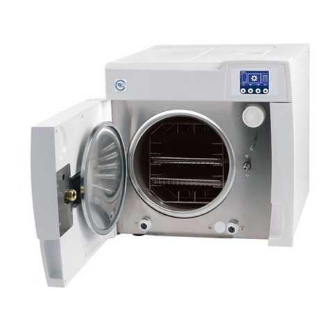
Mocom B28 Series User manual

Operating instructions
classic
Family of Steam sterilizers B28 series - B CLASSIC models:
B Classic-28

III
REVISIONS
The following table lists subsequent editions/revisions of the manual.
The “Description” eld brief explains the subject of the latest revision.
Code Rev. Date Description
97050949 003-2017First issue
TABLE OF CONTENTS
INTRODUCTION....................................................................................................................................1
SYMBOLS USED IN THE MANUAL ...............................................................................................................................1
SYMBOLS ON EQUIPMENT ..........................................................................................................................................1
APPLICABLE EUROPEAN DIRECTIVES ............................................................................................................................1
INTENDED USE ...................................................................................................................................................................1
IMPORTANT NOTES ......................................................................................................................................................2
PURPOSE OF THE MANUAL .............................................................................................................................................2
GENERAL WARNINGS ........................................................................................................................................................2
CONTENTS OF THE PACKAGE...........................................................................................................3
DIMENSIONS AND WEIGHT ...............................................................................................................................................3
DESCRIPTION OF THE CONTENTS ..................................................................................................................................3
HANDLING THE PRODUCT ................................................................................................................................................4
PRODUCT INTRODUCTION .................................................................................................................5
INTRODUCTION ..................................................................................................................................................................5
GENERAL CHARACTERISTICS..........................................................................................................................................5
FRONT..................................................................................................................................................................................6
REAR ...................................................................................................................................................................................7
LCD ICONS ..........................................................................................................................................................................8
OPERATING CYCLE EXAMPLE..........................................................................................................................................9
INSTALLATION....................................................................................................................................10
INTRODUCTION ................................................................................................................................................................10
COMPARTMENT DIMENSIONS FOR BUILT-IN INSTALLATIONS....................................................................................10
GENERAL INSTALLATION PRECAUTIONS ..................................................................................................................... 11
ELECTRICAL CONNECTIONS .......................................................................................................................................... 11
DIRECT CONNECTION TO A CENTRALIZED DRAINING POINT.................................................................................... 12
FIRST START-UP ................................................................................................................................13
TURNING ON THE EQUIPMENT.......................................................................................................................................13
MAIN MENU ......................................................................................................................................................................14
FILLING DISTILLED WATER ............................................................................................................................................15
MANUAL FILLING.........................................................................................................................................................15
AUTOMATIC FILLING................................................................................................................................................... 15
CONFIGURATION ...............................................................................................................................16
SETTINGS..........................................................................................................................................................................16
PREPARING THE MATERIAL.............................................................................................................29
INTRODUCTION ................................................................................................................................................................29
TREATING THE MATERIAL BEFORE STERILIZATION....................................................................................................29
ARRANGING THE..............................................................................................................................................................30
LOAD ..................................................................................................................................................................................30
STERILIZATION CYCLES .................................................................................................................32
EXTRA DRYING...................................................................................................................................34

IIII
PROGRAMMED STARTING................................................................................................................35
RUNNING THE CYCLE ......................................................................................................................................................36
RESULT OF THE CYCLE...................................................................................................................................................36
DOOR OPENING AT CYCLE END.....................................................................................................................................36
MATERIAL STORAGE........................................................................................................................................................37
TEST PROGRAMS ..............................................................................................................................38
INTRODUCTION ................................................................................................................................................................38
CYCLE HELIX TEST/B&D (ONLY FOR B VERSIONS) .....................................................................................................38
CYCLE VACUUM TEST .....................................................................................................................................................40
VACUUM TEST + HELIX TEST/B&D CYCLE (ONLY FOR B VERSIONS)........................................................................ 41
H2O TEST (ONLY FOR B VERSIONS) ..............................................................................................................................41
DOOR OPENING ...............................................................................................................................................................42
USED WATER DRAIN ........................................................................................................................................................43
DETACHING THE PIPE ................................................................................................................................................43
MANUAL INTERRUPTION ................................................................................................................................................44
DATA MANAGEMENT .........................................................................................................................45
APPENDIX – TECHNICAL CHARACTERISTICS...............................................................................49
SUMMARY TABLE..............................................................................................................................................................49
SAFETY DEVICES .............................................................................................................................................................50
WATER SUPPLY CHARACTERISTICS .............................................................................................................................51
APPENDIX – PROGRAMS..................................................................................................................52
INTRODUCTION ................................................................................................................................................................52
PROGRAM SUMMARY TABLE B CLASSIC-28
120 V~ 60 HZ......................................................................................................................................................................60
STERILIZATION PROGRAM DIAGRAM............................................................................................................................61
DIAGRAMS OF THE TEST PROGRAMMES .....................................................................................................................63
EXAMPLES OF PRINTED REPORTS ............................................................................................................................... 64
APPENDIX – MAINTENANCE.............................................................................................................65
INTRODUCTION ................................................................................................................................................................65
ORDINARY MAINTENANCE PROGRAM ..........................................................................................................................65
SCHEDULED MAINTENANCE MESSAGES................................................................................................................65
MAINTENANCE DESCRIPTION .......................................................................................................................................67

IIIIIIIII
CLEAN GASKET AND PORTHOLE..............................................................................................................................67
CLEAN EXTERNAL SURFACES ..................................................................................................................................67
CLEAN STERILIZATION CHAMBER AND ACCESSORIES .......................................................................................67
DISINFECT EXTERNAL SURFACES ...........................................................................................................................67
BOILER FILTER CLEANING ........................................................................................................................................68
DOOR LOCK LUBRICATION........................................................................................................................................68
DUST FILTER CLEANING (ONLY FOR B VERSIONS) ...............................................................................................69
REPLACE THE BACTERIOLOGICAL FILTER .............................................................................................................69
WATER TANK CLEANING ............................................................................................................................................69
BOILER GASKET REPLACEMENT..............................................................................................................................69
PERIODIC STERILIZER VALIDATION...............................................................................................................................70
DISPOSAL AT END-OF-LIFE .............................................................................................................................................70
APPENDIX – GENERAL PROBLEMS ................................................................................................71
INTRODUCTION ................................................................................................................................................................71
ANALYSIS AND RESOLUTION OF PROBLEMS...............................................................................................................71
APPENDIX – ALARMS........................................................................................................................73
INTRODUCTION ................................................................................................................................................................73
ALARM INTERVENTION....................................................................................................................................................73
ALARM DURING A CYCLE...........................................................................................................................................73
SYSTEM RESET..................................................................................................................................74
ALARM CODES..................................................................................................................................................................75
ANALYSIS AND RESOLUTION OF PROBLEMS...............................................................................................................79
APPENDIX – ADMIN USER PIN RESET ............................................................................................88
APPENDIX – ACCESSORIES .............................................................................................................89
PRINTER CONNECTION .............................................................................................................................................90
APPENDIX – TECHNICAL SUPPORT................................................................................................91


1
INTRODUCTION This manual describes all procedures for the correct use of the device and instructions for deri-
ving the full benet from its features.
In any case, we will be available to provide explanations and to receive any suggestions you may
have for improving our products or services.
NOTE
PAY SPECIAL ATTENTION TO PARAGRAPHS INDICATED BY THE POINTING
FINGER.
WARNING
THIS SYMBOL INDICATES A POTENTIAL DANGER OF INJURY. FOLLOW
THE PROCEDURES DESCRIBED IN THE MANUAL TO AVOID INJURING
THE USER AND/OR OTHERS.
DANGER
THIS SYMBOL INDICATES A POTENTIAL DANGER OF PROPERTY DAMAGE.
FOLLOWS THE INSTRUCTIONS IN THE MANUAL TO PREVENT POTENTIAL
DAMAGE TO MATERIALS, EQUIPMENT OR OTHER PROPERTY.
DANGER
THIS SYMBOL INDICATES A POTENTIAL DANGER DUE TO HIGH TEMPERA-
TURE.
Potenzial hazard due to high temperature.
Equipment in accordance with applicable directives.
Symbol for disposal in accordante with Directive 2012/19/UE.
Consult the user manual.
The product described in this manual is manufactured in accordance with the highest safety
standards and doesn't represent any danger for the operator if used according to the following
instructions. The product is in accordance with the following European Directive as applicable:
2006/95/CE, for the approximation to the legislation of the Members States related to low vol-
tage equipment.
2004/108/CE, for the approximation to the legislation of the Members States related to the elec-
tromagnetic compatibility;
93/42CEE and subsequent changes, concerning the medical devices.
WARNING
THE DEVICE MUST ONLY BE USED BY QUALIFIED PERSONNEL. IT MAY
NOT BE USED OR HANDLED BY INEXPERT AND/OR UNAUTHORIZED
PERSONNEL FOR ANY REASON.
WARNING
THE STERILIZER IS NOT A MOBILE OR PORTABLE DEVICE.
APPLICABLE
EUROPEAN
DIRECTIVES
Symbols used in the
manual
Symbols on
equipment
INDICATION
FOR USE
The Family of steam Sterilizers B 28 series are table top steam sterilizers to be used in medical
and dental practices, hospitals, clinics, nursing homes, laboratories and other facilities to
sterilize re-usable surgical instruments (including dental handpieces) and medical materials,
heat and moisture resistant and compatible with steam sterilization process.
The Family of Steam Sterilizers B 28 series is validated for sterilization of fabric packs/textiles
for sterilization programs C1 and C2.
The Family of Steam Sterilizers B 28 series is validated for sterilization up to 9 dental
handpieces for sterilization programs C1 and C2.
The Family of Steam Sterilizers B 28 series is validated for sterilization up to 6 lumen devices
(specifications in the "PROGRAM SUMMARY TABLE").
The device shall not be used for the sterilization of fluids, liquids or pharmaceutical products.
2011/65/EU (Rohs II) on the restriction of the use of certain hazardous substances in
electrical and electronic equipment.

2
Important notes
NOTE
THE MANUAL INFORMATION ARE SUBJECT TO CHANGES WITHOUT ANY
NOTICE.
THE MANUFACTURER IS NOT RESPONSIBLE FOR DIRECT, INDIRECT OR
ACCIDENTAL DAMAGE RESULTING FROM OR RELATING TO THE PROVI-
SION OR USE OF THIS INFORMATION.
THIS DOCUMENT MAY NOT BE REPRODUCED, ADAPTED OR TRANSLA-
TED, IN PART OR IN FULL, WITHOUT THE PRIOR WRITTEN PERMISSION
OF THE MANUFACTURER.
PURPOSE OF
THE MANUAL
The purpose of this manual is to provide instructions for:
– becoming generally familiar with the product;
– its correct installation and conguration;
– its safe, efcient use;
– handling materials before and after sterilization.
Its APPENDIXs also provide:
– the product's general technical specications;
– sterilization program specications;
– maintenance;
– troubleshooting;
– a variety of other documentation.
When using this product, always follow the instructions in the manual and never use for anything
other than its intended purpose.
WARNING
THE USER IS RESPONSIBLE FOR ALL LEGAL REQUIREMENTS RELATED
TO THE INSTALLATION AND USE OF THIS PRODUCT. THE MANUFACTU-
RER WILL NOT BE RESPONSIBLE FOR ANY BREAKAGE, MALFUNCTIONS,
PROPERTY DAMAGE OR INJURY IN THE EVENT THAT THE PRODUCT IS
NOT INSTALLED OR USED CORRECTLY.
Please observe the following precautions in order to avoid injury or property damage:
– Use ONLY high-quality demineralised and/or distilled water.
WARNING
THE USE OF WATER OF INADEQUATE QUALITY CAN SEVERELY DAMAGE
THE DEVICE.
SEE APPENDIX TECHNICAL CHARACTERISTICS IN THIS REGARD.
–Do not pour water or other liquids on the device;
–Do not pour inammable substances on the device;
–Do not use the device in the presence of gas or explosive or inammable vapors;
– Before performing any maintenance or cleaning, ALWAYS DISCONNECT the electricity.
DANGER
WHENEVER IT IS NOT POSSIBLE TO DISCONNECT THE ELECTRICITY TO
THE DEVICE, OR IF THE EXTERNAL POWER GRID SWITCH IS FAR AWAY
OR, AT ANY RATE, NOT VISIBLE TO THE MAINTAINER, PLACE A WORK IN
PROGRESS SIGN ON THE EXTERNAL POWER GRID SWITCH AFTER TUR-
NING IT OFF.
– Make sure the electrical system is grounded conforming to current laws and/or standards;
–Do not remove any label or nameplate from the device; request new ones, if necessary.
– Use only original replacement parts.
WARNING
THE FAILURE TO OBSERVE THE ABOVE, RELEASES THE MANUFACTU-
RER FROM ALL LIABILITY.
GENERAL
WARNINGS

2
3
5
6
8
9
4
1
7
10
3
NOTE
CHECK THE INTEGRITY OF THE
PACKAGE UPON RECEIPT.
Once the package is opened, check that:
– the supply matches the specications of the order
(see the accompanying document);
– that there is no obvious product damage;
Dimensions and weight
A. Height 600 mm
B. Width 600 mm
C. Depth 700 mm
Total weight 65 kg
NOTE
IN THE CASE OF A WRONG PRODUCT, MISSING PARTS OR ANY TYPE OF
DAMAGE, IMMEDIATELY PROVIDE A DETAILED DESCRIPTION TO THE RE-
SELLER AND THE TRANSPORTER THAT MADE THE DELIVERY.
In addition to the steriliser, the package contains:
1. No. 6 stainless steel wire instrument tray;
2. Stainless steel wire tray support;
3. Operating documentation (with CD-ROM);
4. Lubricant for door lock mechanism;
5. Tray extractor;
6. Extra bacteriological lter;
7. Rubber hose with quick-coupling for manual water drainage;
8. 1/8” swivel angular connector;
9. 5mm socket wrench for manual door unlocking;
10. Plastic tube for direct water drainage with fastening clamp;
11. Rear spacers.
Where possible, the packaged product must be handled using suitable mechanical means (forklift
truck, transpallet, etc.) and following the instructions shown on the package.
DIMENSIONS
AND WEIGHT
DESCRIPTION OF
THE CONTENTS
B
A
C
CONTENTS OF
THE PACKAGE

4
In the case of manual handling, the product must be lifted by two persons using the handles cut
in the side of the box.
Once the sterilizer has been taken out of the box, it must be lifted by two persons using appro-
priate means and possibly handled with a lift truck or similar.
WARNING
WE RECOMMEND THAT THE DEVICE BE TRANSPORTED AND STORED
AT A TEMPERATURE NO LOWER THAN 5 °C. PROLONGED EXPOSURE TO
LOW TEMPERATURE AN DAMAGE THE PRODUCT.
NOTE
KEEP THE ORIGINAL PACKAGING AND USE IT WHENEVER THE DEVICE IS
TO BE TRANSPORTED. THE USE OF DIFFERENT PACKAGING COULD DA-
MAGE THE PRODUCT DURING SHIPMENT.
DANGER
BEFORE TRANSPORT, LEAVE THE DEVICE TURNED-OFF FOR ABOUT 30
MINUTES AFTER THE LAST PROGRAM FINISHES AND DRAIN THE DISTIL-
LED WATER AND USED WATER TANKS SO THAT THE ALL THE HOT INTER-
NAL PARTS WILL HAVE TIME TO COOL.
HANDLING THE
PRODUCT
CONDITIONS FOR
STORAGE AND
TRANSPORT
TEMPERATURE: between +5° C and +70° C
HUMIDITY: between 20% and 80%
PRESSURE: between 50 and 110 kPa

5
PRODUCT
INTRODUCTION
INTRODUCTION
GENERAL
CHARACTERISTICS
The Classic series sterilisers are the new products offered by MOCOM in the field of small
water steam sterilisers, equipped with type B (EN 13060) cycles, as well as the new point of
reference with respect to safety, performance, flexibility and ease of use.
It is a sophisticated but, at the same time, easy to use device that, thanks to its wide range of
conguration options and patented operating devices, satises every need for sterilizing medical
devices, guaranteeing the maximum performance under all conditions.
It also features a better way of relating to users who, rather than having to adapt to the machine
and its characteristics, are able to "converse" with it and congure it to meet their own needs.
Thanks to its remarkable ease of use, small size and pleasant appearance, it is the ideal partner
for all professional who demand the maximum sterilization safety.
A Classic series steriliser is an electronic water steam steriliser that is entirely operated by a
micro-processor with a large, printed stainless steel sterilisation chamber.
It is characterized by an advanced fractionated vacuum system for the complete removal of air,
even from hollow, porous materials, and an effective nal vacuum drying phase capable of elimi-
nating all traces of humidity from any load.
Its exclusive steam generation system, effective plumbing circuit and electronic management
(supplemented by high-precision sensors) guarantees high process execution speeds and excel-
lent thermodynamic parameter stability.
Moreover, its Process Evaluation System constantly monitors all the machine's “vital” parameters
in real-time, guaranteeing absolute safety and a perfect result.
It offers users 6 sterilization programs (of which one completely PRESETble), all equipped with
customizable, optimized drying for the fast, effective sterilization of the various types of loads
(instruments and materials) used in a medical environment.
All the cycles can immediately be selected on the clear LCD screen, which also allows extensive
conguration of the device according to the user’s needs.
Please refer to the chapter, “Conguration” for more detail.
Like in the best tradition, also the new range of autoclaves Classic have the most complete,
sophisticated and advanced safety systems available today, giving the user a guarantee against
any electrical, mechanical, thermal or functional fault.
NOTE
FOR THE DESCRIPTION OF THE SAFETY DEVICES, REFER TO THE APPEN-
DIX TECHNICAL CHARACTERISTICS.

6
FRONT
LCD display and con-
trol panel
Sterilization chamber
Door
Door closing system
Bacteriological lter
Water drain lter
On/Off switch
Used water drain quick connector
Door
Distilled water top-up quick-cou-
pling (ONLY FOR B VERSIONS)
Dust lter
(ONLY FOR B
VERSIONS)
Distilled water tank drain quick-
coupling
Quick connector Service only (laser
marked label)

7
REAR
Heat exchanger
Power cable connection
Mains fuses
Automatic lling electrical connection
(ONLY FOR B VERSIONS)
Serial cable connection
Data label
Rear spacer fastening
slots
Connection for automatic distilled
water filling (only for PURE 100/500
and the automatic filling accessory kit)
(water inlet connector) (ONLY FOR B
VERSIONS)
Connection for Direct water
(water drain connector)

11/04/13 10:54
OK
8
LCD ICONS
Selection of the sterilizer settings (SETUP)
11/04/13 10:54
Selection for data management
11/04/13 10:54
Sterilization cycle selection
Selection of the test cycles
NOTE
OTHER PARTICULAR SYMBOLS RELATING TO THE VARIOUS CONDITIONS
OF USE WILL BE DESCRIBED IN THE RELATIVE PARAGRAPHS.
11/04/13 10:54
TIME
SELECTION
ICONS
DATE
DOOR OPENING
11/04/13 10:54
INCREASE
BUTTON
DECREASE
BUTTON CONFIRMATION
BUTTON

9
The Classic series sterilisation programme can be effectively described as a succession of pha-
ses, each one with a very precise objective.
For example, the universal program (cycle B, 134°C - 4’): after loading the material in the cham-
ber, closing the door, selecting the program and starting the cycle (after locking the door opening
mechanism), the following sequence will be suggested (see the graph below):
1. preheating the generator and sterilization chamber;
2. removing the air and penetration of the material by steam through a series of vacuum (extraction
of the uid from the sterilization chamber) and pressure(injection of steam into the chamber)
phases;
3. raising the pressure, with the consequent increase in the temperature of the steam, until reaching
the conditions required for sterilization (in the example, 134 °C);
4. stabilizing the pressure and temperature;
5. sterilizing for the required time (in the example, 4 minutes);
6. depressurizing the sterilization chamber;
7. vacuum-drying phase;
8. ventilating the load with sterile air;
9. bringing the pressure of the sterilization chamber back to the atmospheric level.
Having reached this last phase, you can unlock the door and remove the load from the steriliza-
tion chamber.
It should be emphasized that phases 1, 3, 4, 6 and 9 are identical in all cycles, with slight varia-
tions of duration that are solely dependent on the quantity and consistency of the load and the
heating conditions of the sterilizer while phases 2, 5, 7 and 8 clearly vary their conguration and/
or duration on the basis of the cycle selected (and, as a consequence, the type of load) and the
choices made by the user.
0.00
1.00
2.00
2.10
Pres sure (bar)
Time (
min)
VACUUM DRYING
PR OC ESS
SINGLE VACUUM PULSE
-0.80
NOTE
PLEASE REFER TO APPENDIX PROGRAMS FOR MORE DETAIL.
OPERATING CYCLE
EXAMPLE

A
B
A
C
B
10
The rst and fundamental step in achieving good sterilizer operation, long life and complete use
of its features is a correct, careful installation. Moreover, this precaution will avoid the danger of
physical injury or property damage, not to mention malfunctions and damage to the machine. So,
please follow the instructions in this chapter scrupulously.
NOTE
CUSTOMER SUPPORT (SEE APPENDIX) WILL ANSWER YOUR QUESTIONS
AND PROVIDE ADDITIONAL INFORMATION.
THE STERILIZER HAS PASSED ALL REQUIRED INSPECTIONS BEFORE
BEING PLACED ON THE MARKET. IT DOES NOT REQUIRE ANY ADDITIONAL
CALIBRATION BEFORE BEING PLACED IN SERVICE.
Dimensions and
weight
A. Height (total) 500 mm
B. Width (total) 480 mm
C. Depth (excluding
rear connections) 600 mm
Total weight 60
kg
Electricity.
The electrical system to which the sterilizer will be connected must be suitably dimensioned ba-
sed on the electrical characteristics of the device. This information is shown on the back of the
machine.
When installing the sterilizer inside a cabinet, you must
provide adequate space all around the device to pro-
vide effective ventilation as well as a large enough
opening in the back that, in addition to allowing the
passage of the power cord will also provide an ade-
quate air ow and the consequent optimum cooling
of the heat exchanger.
The compartment where the steriliser will be kept must
have the following minimum dimensions:
Dimensions
A. Height 500 mm with FRONT FILLING KIT
670 mm with FILLING FROM THE TOP (door)
B. Width 600 mm
WARNING
COMPARTMENT DIMENSIONS LESS THAN THOSE SHOWN MAY COM-
PROMISE THE CORRECT CIRCULATION OF AIR AROUND THE DEVICE
AND MAY NOT PROVIDE ADEQUATE COOLING, WITH THE CONSEQUENT
DETERIORATION OF PERFORMANCE AND/OR POSSIBLE DAMAGE.
NOTE
IF THE FILLING AND DRAINAGE DOORS ARE NOT ACCESSIBLE FROM THE
TOP AFTER THE DEVICE HAS BEEN BUILT IN, IT IS ADVISABLE TO USE THE
FRONT ATTACHMENTS (FRONT FILLING KIT).
IF THE MAIN SWITCH IS INACCESSIBLE WHEN INSTALLED IN THE COM-
PARTMENT, USE AN ELECTRIC PLUG THAT INCORPORATES AN ON/OFF
SWITCH.
DO NOT REMOVE THE UPPER COVER OR ANY OTHER EXTERNAL PART.
WHEN INSTALLED IN THE COMPARTMENT, THE DEVICE MUST BE COM-
PLETE WITH ALL ITS PARTS.
PLEASE REFER TO APPENDIX TECHNICAL CHARACTERISTICS FOR COM-
PLETE TECHNICAL DATA.
INSTALLATION
INTRODUCTION
COMPARTMENT
DIMENSIONS
FOR BUILT-IN
INSTALLATIONS

11
Obey the following warnings for the correct operation of the device and/or to avoid risky situa-
tions:
– Install the sterilizer on a at and perfectly horizontal surface.
– Make sure that the support surface is strong enough to support the equipment weight (about
60 kg);
– Leave adequate space for ventilation (at least 10 cm on each side) all around the sterilizer,
especially in back.
– If the device is built-in to a cabinet, be sure to respect the warnings in the preceding paragraph,
avoiding an obstructions to the air intake;
– Do not install the sterilizer near tubs, sinks or similar places, to avoid contact with water or
liquids. This could cause short circuits and/or potentially dangerous situations for the operator;
– Do not install the sterilizer in a place that is excessively humid or poorly ventilated;
– Do not install the machine were there is gas or inammable and/or explosive vapors;
– Install the device so that the power cord is not bent or crushed. It must run freely all the way
to the socket.
– Install the device that any external ll/drain tubing is not bent or crushed. They must run freely
to the drain tank.
The sterilizer's must be connected to a socket of the electrical system of adequate capacity for
the device's absorption and ground provided, in conformity with current laws and/or standards.
The socket must be suitably protected by a breaker having the following characteristics:
– Nominal current In16 A
– Differential current IDn0,03 A
WARNING
THE MANUFACTURER WILL NOT BE LIABLE FOR DAMAGES CAUSED BY
INSTALLING THE STERILIZER ON AN INADEQUATE ELECTRICAL SYSTEM
AND/OR NOT EQUIPPED WITH A GROUND.
NOTE
ALWAYS CONNECT THE POWER CORD DIRECTLY TO THE SOCKET. DO
NOT USE EXTENSION CORDS, ADAPTERS OR OTHER ACCESSORIES.
GENERAL
INSTALLATION
PRECAUTIONS
ELECTRICAL
CONNECTIONS

12
– Remove the cap holding clip on the rear of the autoclave.
– Fit the plastic tube on the elbow union (provided).
– Fit the union and then ret the clip.
– Fasten the clip provided to the drain siphon.
– Cut the hose to the right length and insert its free end into the centralized draining connector
locking it with the dedicated ring nut.
NOTE
MAKE SURE THE TUBE IS NOT BENT, CRUSHED OR OBSTRUCTED IN ANY
WAY.
The following diagram provides an indicative arrangement of the components:
NOTE
THE CONNECTION POINT TO THE CENTRAL DRAIN MUST BE LOWER
THAN THE STERILIZER'S SUPPORT SURFACE. OTHERWISE, THE TANK
MAY NOT EMPTY CORRECTLY.
NOTE
FOR AUTOMATIC FILLING SYSTEMS (PUMP, PURE 100, PURE 500, EV7)
THE DIRECT DRAIN MUST ALWAYS BE CONNECTED.
THIS ACTS AS AN OVERFLOW, AND, IF FOR SOME REASON, THE FILLING
SYSTEM DOES NOT STOP, THE WATER SEEPS FROM THE FEED TANK
INTO THE DRAIN TANK AND FLOWS OUT THE DIRECT DRAIN, THUS PRE-
VENTING FLOODING.
DIRECT CONNECTION
TO A CENTRALIZED
DRAINING POINT
Support
plane
To the centralized
draining point
Drain
siphon
Clamp

13
Once the sterilizer has correctly been installed, turn it on with the main switch on the right-hand
side of the machine.
FIRST START-UP
TURNING ON THE
EQUIPMENT
WARNING
DO NOT TURN ON THE STERILIZER, IF USB KEY IS INSERTED.
When the sterilizer is turned on, the following page appears:

14
11/04/13 10:54
OK
Once the start procedure has been completed, the main menu shown below appears on the
display.
The device waits for selection of the desired program (see section “Program Selection”).
DANGER
TO PREVENT BURNS, BE CAREFUL NOT TO TOUCH THE STERILIZA-
TION CHAMBER, THE CHAMBER EQUIPMENT OR THE INSIDE OF THE
DOOR WITH BARE HANDS.
MAIN MENU

15
The rst time the sterilizer is used, and later when the MIN water level indicator comes on, you will
have to ll, or top-off, the internal distilled water tank.
Open the loading door.
Pour in water taking care not to exceed the maximum level (MAX) indicated inside the tank. Close
the door.
Be carefulnot to spill any water on the machine, and if so, immediately dry it off.
WARNING
THE TANK MUST BE FILLED BEFORE THE CYCLE STARTS OR AFTER ITS
COMPLETION.
DO NOT OPEN THE TANK DOORS DURING CYCLE EXECUTION IN ORDER TO
PREVENT WATER LEAKS.
Refer to the Appendix "ACCESSORIES".
Manual lling
Automatic lling
FILLING DISTILLED
WATER
BEEP
This manual suits for next models
1
Table of contents
Other Mocom Laboratory Equipment manuals

Mocom
Mocom millenium B2 User manual

Mocom
Mocom Autoklav B Futura 28 Liter User manual

Mocom
Mocom B FUTURA User manual

Mocom
Mocom SUPREME 17 User manual

Mocom
Mocom B Futura-17 User manual

Mocom
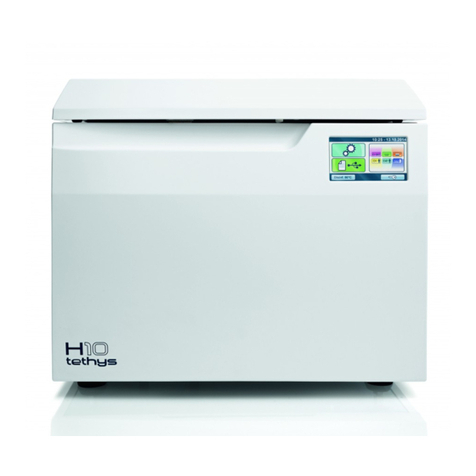
Mocom Tethys H10 User manual

Mocom
Mocom millennium B User manual

Mocom
Mocom Tethys D60 User manual

Mocom
Mocom Exacta User manual

Mocom
Mocom S Classic 17 User manual
Popular Laboratory Equipment manuals by other brands

Sartorius
Sartorius Cubis MCE Series operating instructions

IKA
IKA 20015943 operating instructions

BIO RAD
BIO RAD Ultramark user manual

Cole Parmer
Cole Parmer SPEX 8000M Operation manual

Beckman Coulter
Beckman Coulter GH-3.8 Instructions for use

CleanControlling
CleanControlling CPS3 apex instruction manual