User Instructions
Should you nd your equipment is no longer of use,
please dispose of in a responsible manner. Please
contact Modulift if you need further guidance
© Copyright 2019 Modulift.
All rights reserved.
Do’s & Don’ts
Do ensure enough clearance between frame and
the load to prevent the load hitting the frame.
Any collision could cause failure of the frame.
Do not exceed the individual WLL of any Corner
Unit or T-Piece taking into account CoG osets.
The frame is designed to lift a single solid item
using 6 points of the frame.
To ensure no slings are slack, use turnbuckles on
the central top slings, use matching top slings
for the corners, and matching bottom slings
all round. For oset CoGs, or where loads have
dierent spans to the frame, more turnbuckles
will be required for the top and/or bottom slings.
Turnbuckles must be adjusted until all slings
are in tension. Contact Modulift for advice if
in doubt.
Ensure that Fig.2 is checked and followed.
When connecting Corner Units directly to
T Pieces i.e. no struts between these
components, assembly may be dicult due to
fabrication tolerances. Please contact Modulift
for advice.
Do not hang any loads from the Strut tube
or anges.
Do not exceed the stated WLL for your span.
Do not rig the lower slings more than 6°
from vertical.
Assembly Procedure
Check the ID plates on each Modulift
component to ensure the correct size is used.
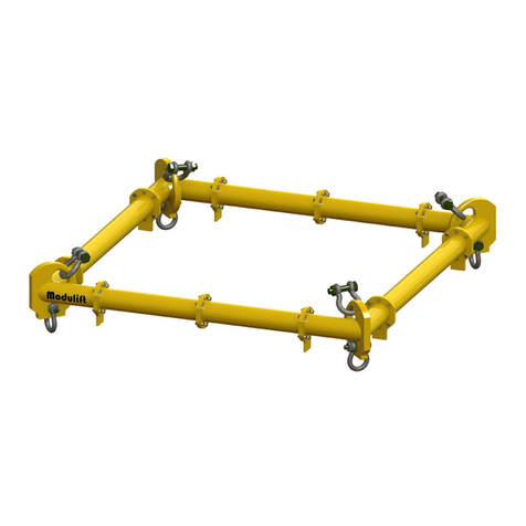
Lay out the Struts, T-Pieces and Corner Units in
the correct conguration.
Check all anges are clear from debris, sand etc.
before connection.
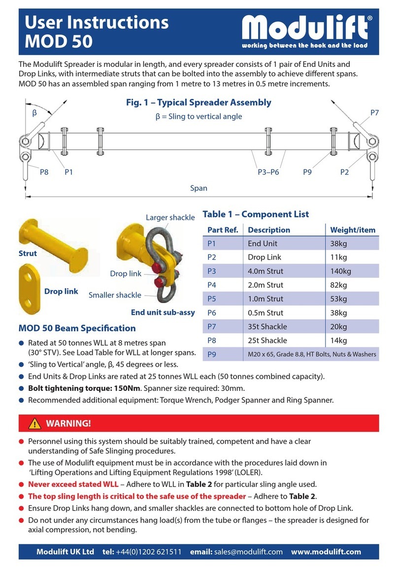
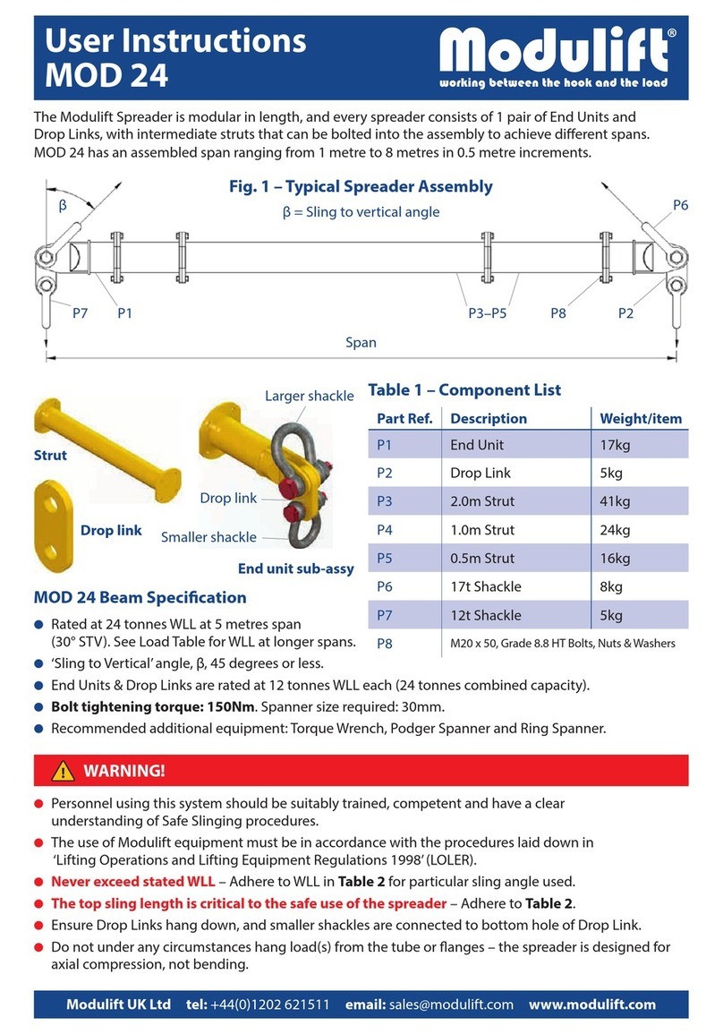
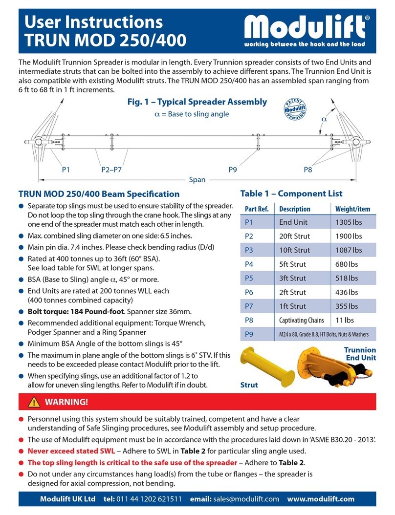
Bolt the components together* using bolts, nuts
& washers provided. Tighten the bolts to torque
as shown overleaf.
Loop the top Shackles through the bows of the
Corner Units so they contact ‘bow-to-bow’. The
eye of the top slings can then be passed through
the jaws of the Shackles and the pins replaced.
Loop the top Shackles through the remaining
top slings and connect Shackles to the top of
the T-Pieces.
Loop the bottom Shackles through the eyes of
the drop slings and connect to the bottom of the
Corner Units and T-Pieces with the Shackle pins.
Attach the lower slings to the load to be lifted.
The assembled Spreader Frame and lifting rig
must be thoroughly checked by a competent
person prior to lifting.
*The use of a Podger Spanner will aid in
assembly by helping to align the bolt holes by
forcing it through.
Fig. 2
25% S < A < 75% S
25% S < B < 75% S
Where S is the overall span of the side with the
T-Piece, and A & B are intermediate lengths.
A
B
S
CMOD 6: 6-Point US NOVEMBER 2019
CMOD 6: 6-Point Frame


