manuals.online logo
Brands
  1. Home
  2. •
  3. Brands
  4. •
  5. Mitutoyo
  6. •
  7. Measuring Instrument
  8. •
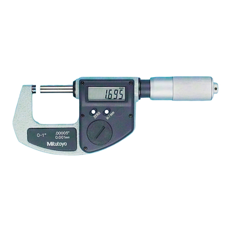
  9. Mitutoyo QuantuMike MDE-MX User manual

Mitutoyo QuantuMike MDE-MX User manual

Mitutoyo Corporation 20-1, Sakado 1-Chome, Takatsu-ku, Kawasaki-shi, Kanagawa 213-8533, Japan Date of publication: December 1, 2021
Printed in Japan
1. Names of Components
0
-
1”
0.001
mm
.00005”
⑧
⑨
⑩
④③②① ⑤ ⑥ ⑦
0
-
1”
0.001
mm
.00005”
⑪
①Anvil
②Spindle
③Swivel clamp
(locks the spindle to prevent motion)
④Display unit (LCD)
⑤Sleeve
⑥Thimble ratchet
(constant pressure device built-in)
⑦Speeder ratchet
(constant pressure device built-in)
⑧Cover (type with output only)
⑨Data output connector
(type with output only)
⑩Battery compartment cover (at rear)
⑪Waterproof mark
■Display Unit (LCD)
⑫⑬
⑮
⑭
⑯
⑰
⑱
⑲
⑳
⑫[HOLD] key
⑬[ZERO/ABS] key
⑭[in/mm] key (in/mm products only)
⑮[ORIGIN] key
⑯Sign display
⑰Function Lock display
⑱Hold display
⑲Low voltage display
⑳INC display
㉑Preset display
㉒Unit display
2. Installing the Battery
Always align the battery compartment cover with the threads and install so that the seal does not
protrude. The product may display an error or malfunction if the battery compartment cover or
seal is not mounted correctly.
Tips
• Be sure to use SR44 (silver oxide button battery Part No. 938882) for the battery.
• Do not rotate the ratchet until the count is displayed. Initial setting of the electrical components
may fail, or the product may not count normally. If you mistakenly move the ratchet, reinstall the
battery.
• The battery supplied is for confirming the functions and performance of the product. Note that
this battery may not fulfill the predetermined life.
• Malfunction or damage due to depleted batteries, etc. is not covered by the warranty.
• Follow local rules and regulations regarding battery disposal.
The battery is not installed into the product at purchase. Install the battery as follows.
1Insert a coin or similar object into the groove on the battery compartment cover, and turn it to
the left to remove the cover.
2Install the battery (SR44) with the positive side facing up.
3Position the battery compartment cover and rotate clockwise to attach.
4Press the [ORIGIN] key.
》Count display appears and counting starts.
Moving on, set the ORIGIN (reference point) (refer to "4. ORIGIN (Reference Point) Setting").
SR44
1 2 3
4ORIGIN
Seal
Tips
• Re-installing the battery will erase the ORIGIN (reference point) position. Perform reference
point setting again (refer to "4. ORIGIN (Reference Point) Setting").
• If an abnormal display is shown, such as an error display or not counting, etc., try removing the
battery and reinstalling.
Safety Precautions
To ensure operator safety, use this product in conformance with the directions, functions
and specifications given in this User's Manual.
Use under other conditions may compromise safety.
•
Always keep batteries out of reach of children, and if swallowed, consult a physician immediately.
• Batteries should never be short-circuited, disassembled, deformed or come in contact with
extreme heat or flames.
•
If battery alkaline liquid comes in contact with the eyes, flush eyes immediately with clean
water and consult a physician. If battery alkaline liquid comes in contact with the skin,
flush the exposed area thoroughly with clean water.
• Never attempt to charge the primary battery or reverse the positive-negative terminals
when mounting. Improper battery handling or mounting may cause the battery to explode,
cause battery leakage and/or serious bodily injury or malfunctioning.
• Always handle the sharp measuring faces of this product with care to avoid injury.
• Do not disassemble or modify.
• Do not use or store the product in a place with sudden temperature changes. Adapt the
product to ambient temperature before use.
• Do not store the product in a place with high humidity or a lot of dust.
• Firmly close the battery compartment cover if the product is used in a place where it is
directly exposed to splashes of coolant, etc. For the type with output, when mounting the
output cable and cover, firmly tighten the fixing screws so that there is no gap. As well,
clean and apply anti-rust treatment after use. Rust may cause malfunction.
• Do not use submerged, as coolant ingress cannot be completely prevented. Complete
prevention of coolant ingress, etc., may also not be possible if the product is used in
locations exposed to direct jets of liquid.
• Do not apply excessive force or subject to sudden impacts such as dropping.
• Remove dust, cutting chips, etc. before and after use.
• When cleaning, wipe this product with a soft cloth moistened with diluted neutral
detergent. Do not use an organic solvent such as thinner, which may cause the product to
deform or malfunction.
• Rotating the thimble once will move the spindle 2 mm. Because the spindle moves quickly,
do not allow it to make violent contact with the measuring surface when measuring or
during reference point setting.
• The spindle structure prevents pulling out, so do not try to forcibly retract in excess of the
measurement range.
• Dirt on the spindle may lead to malfunction. If the spindle becomes dirty, wipe it clean with
a cloth containing a small amount of alcohol and apply a small amount of micrometer oil
(Part No. 207000).
• If Micrometer Oil is not available and you must use a commercially available product, we
recommend using an anti-rust agent with low viscosity almost equivalent to ISO VG10.
• Do not write numbers, etc. with an electric pen.
• If the product is to be out of use for three months or more, remove the battery before
storage. Liquid leakage from the battery may damage the product.
QuantuMike
MDE-MX/PX
User's Manual No. 99MAB044A2
Key operation icon
=
> 2 s
=
< 1 s
1
Contents
1. Names of Components ............................................................................................ Page 1
2. Installing the Battery ................................................................................................ Page 1
3. Precautions for Use ................................................................................................. Page 2
4. ORIGIN (Reference Point) Setting .......................................................................... Page 2
5. Measurement Method ............................................................................................. Page 2
6. Key Functions .......................................................................................................... Page 2
7. Function Lock Function (Preventing Accidental Operation) .................................... Page 2
8. Errors and Troubleshooting ..................................................................................... Page 2
9. Specifications .......................................................................................................... Page 3
10. Output Function (Function for Type with Output Only) ............................................ Page 3
11. Options .................................................................................................................... Page 3
12. Off-Site Repairs (Subject to Charge) ....................................................................... Page 3
en
Mitutoyo Corporation 20-1, Sakado 1-Chome, Takatsu-ku, Kawasaki-shi, Kanagawa 213-8533, Japan Date of publication: December 1, 2021
Printed in Japan
3. Precautions for Use
■Measuring Force
• Make sure to use the thimble ratchet or speeder ratchet to
ensure consistent measuring force.
• The appropriate measuring force is achieved with the
following procedure: make light contact between the
measurement surfaces and the workpiece, stop
momentarily, and then manually turn the thimble ratchet or
speeder ratchet about three to five times.
• Rotating the thimble once will move the spindle 2 mm.
Because the spindle moves quickly, be sure to make
contact slowly and gently with the measuring surface when
measuring or during reference point setting.
■Precautions for Measurement
• Use caution when measuring magnetized workpieces. If the product becomes magnetized,
measurement results may be affected.
■Precautions after Use
• After use, clean the entire product and check that none of
the parts are damaged.
If using in places exposed to water-based cutting fluid,
always apply anti-rust treatment after cleaning.
• For storage, leave a gap of 0.2 to 2 mm open for the
measurement surfaces, and release the swivel clamp.
• If the product will not be used for three months or longer,
apply micrometer oil (Part No. 207000) to the spindle to
prevent rust, and store it with its battery removed.
• If Micrometer Oil is not available and you must use a commercially available product, we
recommend using an anti-rust agent with low viscosity almost equivalent to ISO VG10.
4. ORIGIN (Reference Point) Setting
Reference point setting and measurement should be made in the same orientation
and conditions with the procedure as below.
■ORIGIN (Reference Point) Setting
1Clean both anvil and spindle measurement surfaces, together with the gage if it is used, to
remove all debris or dust.
2For 0 to 25 mm measurement range:
After making light contact with both measurement surfaces, stop momentarily, and then apply
the appropriate measuring force (refer to "■Measuring Force" in "3.Precautions for Use").
For above the 0 to 25 mm measurement range:
After clamping the gage between the measuring surfaces, bring the spindle into light contact
with the gage, stop momentarily, and then apply the appropriate measuring force (refer to
"■Measuring Force" in "3.Precautions for Use").
Use a periodically inspected (calibrated) gage (gauge block, setting standard for
outside micrometer, etc.).
3Press the [ORIGIN] key.
》Check that [P] is blinking and the ORIGIN (reference point) value* is displayed (*refer to
"Tips" below).
4Press the [ORIGIN] key again.
》[P] goes out and the ORIGIN (reference point) value is set.
• For 0 to 25 mm measurement range:
3 4
ORIGIN ORIGIN
2
1
0
-
1”
0.001
mm
.00005”
• For above the 0 to 25 mm measurement range (e.g., 25 to 50 mm):
3 4
ORIGIN ORIGIN
1
2
1
-
2”
0.001
mm
.00005”
Release swivel clamp
Tips
• The display of this product automatically turns off if not used for 20 minutes or more. To display
again, either rotate the ratchet or press the [ZERO/ABS] key.
•
If the [ORIGIN] key is accidentally pressed while making a measurement, press the [ZERO/ABS]
key to return to the former state. If this does not enable the product to recover, perform
"4. ORIGIN (Reference Point) Setting" once more.
• The following table shows the relationship between measurement range and ORIGIN (reference
point) value.
Measuring range ORIGIN (reference point) value Measuring range ORIGIN (reference point) value
0 - 25 mm 0.000 mm 0 - 1 in 0.00000 in
25 - 50 mm 25.000 mm 1 - 2 in 1.00000 in
50 - 75 mm 50.000 mm 2 - 3 in 2.00000 in
75 - 100 mm 75.000 mm 3 - 4 in 3.00000 in
■Using a Reference Gage other than the Setting Standard for Outside
Micrometer (Standard Accessory)
First set the ORIGIN (reference point) using the standardly equipped setting standard for outside
micrometer.
1
Turn the ratchet until the target value is displayed, and then press the [HOLD] key to hold the value.
2Press the [ORIGIN] key.
》[P] blinks.
3Clamp the reference object and apply the appropriate measuring force with the constant
pressure device (refer to "■Measuring Force" in "3. Precautions for Use").
4Press the [ORIGIN] key again.
》[P] goes out and setting is complete.
ORIGIN
ORIGIN
HOLD
1 2
3 4
1
-
2”
0.001
mm
.00005”
1
-
2”
0.001
mm
.00005”
Tips
To return to the default ORIGIN (reference point) value, reinstall the battery.
Key operation icon
=
> 2 s
=
< 1 s
5. Measurement Method
• Be sure to perform reference point setting before measurement.
• Bring the measuring surface of the spindle slowly into contact with the workpiece.
Moving too quickly could deform the workpiece and affect measurement results.
Gradually and lightly bring the measurement surfaces into contact with the workpiece in the same
orientation and conditions as for reference point setting, apply the appropriate measuring force,
and then read the display value (refer to "■Measuring Force" in "3. Precautions for Use").
6. Key Functions
■[ZERO/ABS] Key
1 Briefly press the [ZERO/ABS] key.
》[INC] is displayed, and the display
is set to zero.
2Press and hold the [ZERO/ABS] key
(for at least 2 seconds).
》[INC] goes out, and the length from
the reference point (anvil measuring
surface) is displayed.
■[HOLD] Key
1Press the [HOLD] key.
》[H] is displayed, and the display
value is held.
2Press the key again to release the
value.
■[in/mm] Key (in/mm Products Only)
• Press the [in/mm] key.
》  [in] and [mm] switch back and forth each time the
key is pressed.
7. Function Lock Function (Preventing Accidental Operation)
This product has the Function Lock function, which disables the ORIGIN (reference point) function
and ZERO/ABS function in order to avoid accidental changes to the reference point position.
Setting the Function Lock causes [ ] on the LCD to light up and disables the [ORIGIN] key,
[ZERO/ABS] key, and [in/mm] key (in/mm products only), with only the hold operation function
enabled.
1First press and hold the [HOLD] key, and then additionally press and hold the [ZERO/ABS] key
(for at least 2 seconds).
》[H] display and [ ] display light up in sequence ([H] turns off first).
2Perform the same operation to release the Function Lock.
HOLD
+
ZERO/ABSHOLD
+
ZERO/ABS
21
8. Errors and Troubleshooting
Error Display Causes and Countermeasures
Power Voltage Drop
The battery voltage is low. Replace the battery promptly.
Counting Error
A counting error has occurred due to excessive speed or noise.
Try removing the battery and reinstalling.
Counting Error
Initial setting of the electrical components failed, or a counting
error has occurred due to a sensor signal error. Try removing the
battery and reinstalling.
ZERO/ABSZERO/ABS
21
HOLD
21
HOLD
in / mm
2
Rotate about three to five times.
Mitutoyo Corporation 20-1, Sakado 1-Chome, Takatsu-ku, Kawasaki-shi, Kanagawa 213-8533, Japan Date of publication: December 1, 2021
Printed in Japan
9. Specifications
Maximum measuring length Maximum permissible error
J
MPE *1
25 , 50 mm ±1 μm
75 , 100 mm ±2 μm
1 , 2 in ±0.00005 in
3 , 4 in ±0.00010 in
Measuring force*2 : 7 N to 12 N
Resolution : 0.001 mm
0.00005 in (in/mm products only)
Display unit : LCD (6-digit and minus sign)
Power supply : Button type silver-oxide battery (SR44 No.938882), x1
Battery life : Approximately 2.4 years
Temperature range : 5 °C to 40 °C (operating temperature),
-10 °C to 60 °C (storage temperature)
Standard accessories : Wrench (No. 301336), standard bar (equipped as standard with
products with measurement range exceeding 25 mm/1 in)
IP protection level : IP65 (refer to IEC60529 for details).
Dust resistance (level 6) : No ingress of dust allowed.
Protection against water jets (level 5) : Water projected by a nozzle from any direction
shall have no harmful effects.
CE marking/UKCA marking
: EMC Directive/Electromagnetic Compatibility Regulations: EN 61326-1
Immunity test requirement: Clause 6.2 Table 2
Emission limit: Class B
RoHS Directive/The Restriction of the Use of Certain Hazardous Substances
in Electrical and Electronic Equipment Regulations: EN IEC 63000
*1: Maximum permissible error for indicated value via contact with full measuring face
J
MPE (20 °C).
*2: Measuring force when using the speeder ratchet.
10. Output Function (Function for Type with Output Only)
■Display Value External Output
The display value can be output to a device by connecting the product (type with output only) and
the external device with a connection cable (option).
■Connection Cable Installation Method
• Always use the 0-size Phillips screwdriver (No.05CZA619) supplied with the connection cable
(option) when installing/removing screws, and tighten with a torque of 5 to 8 cN·m or so.
Tightening with a high torque could cause damage.
•
When connecting the connection cable, ensure that the connector gasket does not protrude.
If the connector gasket is not installed properly, waterproof functionality may decrease and lead
to malfunctions.
Tips
Note that using this product in a location with high noise may cause malfunctions (flickering or
errors).
1 Use the Phillips screwdriver supplied with the connection cable to remove the cover fixing
screws (M1.7 x 0.35 x 2.5, No.09GAA376).
2Remove the cover.
3Check that the connector gasket (No.04AAC126) is correctly installed at the proper position
(do not remove the connector gasket).
4Mount the connection cable plug.
5Hold the plug manually so that there is no gap between the plug and the connector on the
micrometer body, and fasten using the fixing screws on the connection cable.
1 3 52 4
Connector gasket
■Output Data Format
(1) Output order
(2) All "F"
(3) Sign
(4) Measured
value
(5) Decimal point
(6) Unit
(1)
MSD LSD
(5)
(2)
(1111)
(4)
(3)
+:0(0000)
–:8(0001)
3(1100
)
4(0010
)
5(1010
)
(6)
mm:0(0000)
in:1(1000)
■Timing Chart
0 ms ≦T1 ≦200 ms
0.11 ms ≦T2 ≦0.14 ms (Typ: 0.122 ms)
0.11 ms ≦T3 ≦0.14 ms (Typ: 0.122 ms)
0.22 ms ≦T4 ≦0.27 ms (Typ: 0.244 ms)
T5 ≦80 ms
*1: DATAsw is LOW while the data output key is being pressed.
*2: The time T5 until DATAsw goes to the LOW level and REQ is input is determined by the data
processing device performance.
11. Options
• Connection cable: No.05CZA662 (1 m)
• Connection cable: No.05CZA663 (2 m)
For options other than the above, refer to the General Catalog.
12. Off-Site Repairs (Subject to Charge)
Off-site repair (subject to charge) is required in the case of the following malfunctions. Please
contact the agent where you purchased the product or a Mitutoyo sales representative.
• Faulty spindle operation
If the spindle is scratched, these scratches may interfere while the spindle is retracting, causing
faulty operation.
Operation may also suffer if the spindle is rusted.
• Inconsistent measured values
If there are burrs or nicks generated by an impact on the measuring surfaces, it may affect
measurement repeatability.
• Count value error/faulty operation
If the thimble of this product is retracted too far, the internal sensor will be damaged. This may
cause count errors or faulty operation.
3

This manual suits for next models

1

Other Mitutoyo Measuring Instrument manuals

Mitutoyo QM-Height User manual

Mitutoyo

Mitutoyo QM-Height User manual

Mitutoyo SURFTEST SV-3100 User manual

Mitutoyo

Mitutoyo SURFTEST SV-3100 User manual

Mitutoyo ID-H0530 User manual

Mitutoyo

Mitutoyo ID-H0530 User manual

Mitutoyo QM-Height Series User manual

Mitutoyo

Mitutoyo QM-Height Series User manual

Mitutoyo ID-N User manual

Mitutoyo

Mitutoyo ID-N User manual

Mitutoyo LGF-110ZL-B User manual

Mitutoyo

Mitutoyo LGF-110ZL-B User manual

Mitutoyo 99MAG014M User manual

Mitutoyo

Mitutoyo 99MAG014M User manual

Mitutoyo 99MAB034A1 User manual

Mitutoyo

Mitutoyo 99MAB034A1 User manual

Mitutoyo BA9700 User manual

Mitutoyo

Mitutoyo BA9700 User manual

Mitutoyo ID-U User manual

Mitutoyo

Mitutoyo ID-U User manual

Mitutoyo LG200 User manual

Mitutoyo

Mitutoyo LG200 User manual

Mitutoyo 7210 User manual

Mitutoyo

Mitutoyo 7210 User manual

Mitutoyo IMZ-MJ User manual

Mitutoyo

Mitutoyo IMZ-MJ User manual

Mitutoyo ID-CNX Series User manual

Mitutoyo

Mitutoyo ID-CNX Series User manual

Mitutoyo HDS-H30C User manual

Mitutoyo

Mitutoyo HDS-H30C User manual

Mitutoyo EJ-102N User manual

Mitutoyo

Mitutoyo EJ-102N User manual

Mitutoyo Digimatic MDC-S User manual

Mitutoyo

Mitutoyo Digimatic MDC-S User manual

Mitutoyo IT-012U User manual

Mitutoyo

Mitutoyo IT-012U User manual

Mitutoyo Litematic VL-50A User manual

Mitutoyo

Mitutoyo Litematic VL-50A User manual

Mitutoyo SJ-210 User manual

Mitutoyo

Mitutoyo SJ-210 User manual

Mitutoyo 500-150-30 User manual

Mitutoyo

Mitutoyo 500-150-30 User manual

Mitutoyo ID-C112GXB User manual

Mitutoyo

Mitutoyo ID-C112GXB User manual

Mitutoyo LSM-9506 User manual

Mitutoyo

Mitutoyo LSM-9506 User manual

Mitutoyo 530-101 User manual

Mitutoyo

Mitutoyo 530-101 User manual

Popular Measuring Instrument manuals by other brands

Ecotech Serinus 40 user manual

Ecotech

Ecotech Serinus 40 user manual

ABB NGC8200 user manual

ABB

ABB NGC8200 user manual

Zeta Alarm Limited Fyreye MKII ZAZM-MI installation guide

Zeta Alarm Limited

Zeta Alarm Limited Fyreye MKII ZAZM-MI installation guide

phase II+ UTG-2900 manual

phase II+

phase II+ UTG-2900 manual

Fluidwell F1-A-PD-OS Series installation guide

Fluidwell

Fluidwell F1-A-PD-OS Series installation guide

KEPCO 520K Series instructions

KEPCO

KEPCO 520K Series instructions

GHM G 1410 operating manual

GHM

GHM G 1410 operating manual

GOK SmartBox 4 LAN Assembly and operating manual

GOK

GOK SmartBox 4 LAN Assembly and operating manual

Vernier Go Direct GDX-WRP quick start guide

Vernier

Vernier Go Direct GDX-WRP quick start guide

Lnk SoundWire user manual

Lnk

Lnk SoundWire user manual

HP 3400B User's and service guide

HP

HP 3400B User's and service guide

Motorola R-20010 Maintenance manual

Motorola

Motorola R-20010 Maintenance manual

Datalogic Controller SC6000 installation manual

Datalogic

Datalogic Controller SC6000 installation manual

HBK PAD4001A operating manual

HBK

HBK PAD4001A operating manual

Tenmars TM-188 user manual

Tenmars

Tenmars TM-188 user manual

KERN DLB 160-3A operating instructions

KERN

KERN DLB 160-3A operating instructions

National Instruments CMS-9024 manual

National Instruments

National Instruments CMS-9024 manual

TESTO 535 instruction manual

TESTO

TESTO 535 instruction manual

manuals.online logo
manuals.online logoBrands
  • About & Mission
  • Contact us
  • Privacy Policy
  • Terms and Conditions

Copyright 2025 Manuals.Online. All Rights Reserved.