SL Flat Flex Cable Terminator
Order No: TM-622007700 Release Date: 02-18-99 UNCONTROLLED COPY Page 10 of 20
Revision: F Revision Date: 11-23-15
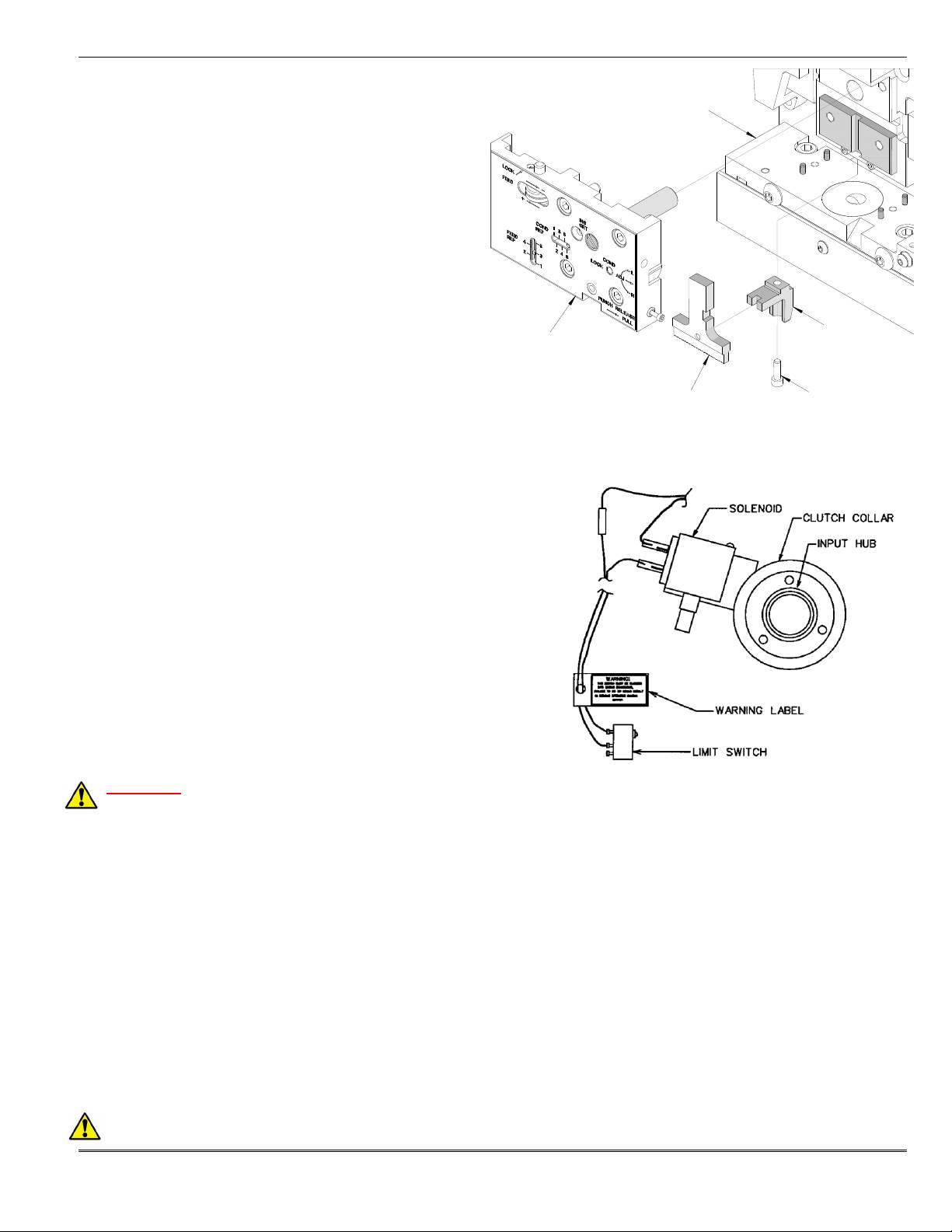
CONDUCTOR ADJ.
LOCK SCREW
5. Always power down the press by pressing the
emergency stop button located on the front of the
control panel. Remove the press guard by unscrewing
the four M10 button head screws. Two are located on
the front bolster plate and one is located on each side.
6. Loosen the M6 conductor adjustment lock screw located
on the front of the punch plate. See Figure 2-5.
7. With a screwdriver, turn the conductor adjusting screw,
located on the right side of the punch plate. Rotating
the adjusting screw clockwise one full turn will lower the
crimp height approximately 0.03mm (.001”). Each
increment on the Conductor Adjustment Indicator
represents approximately 0.13mm (.005”) for a total of
0.65mm (.026”). The “1” setting indicates the highest
crimp height and the “6” setting is the tightest.
8. Tighten the conductor adjusting locking screw.
9. Reinstall the machine guard and repeat the above steps until the desired crimp height is obtained.
Nest-in-Position Indicator Switch Adjustment
CAUTION: Always disconnect power supply before installing or removing tooling.
There is a miniature limit switch 62500-0518 in the Cable Assembly-62200-7721 on the back of the lower tooling. This
switch signals the nest in position for termination. See Figure 2-6. If this switch should work loose or has to be
replaced, it may be necessary to adjust its position. To do
this, follow these instructions:
1. Unplug the power cord.
2. Remove the back cover from the TM42 press.
3. Push the slide assembly into the press.
4. Manually lower the TM42 ram using the wrench supplied
with the press. See TM42 press manual for additional
instructions. Lower the ram until the locator in the ram
mates with the slide assembly in the lower tooling.
5. Adjust switch toward the slide assembly until the switch
is fully actuated but not totally bottomed out.
6. Replace back cover on press.
7. Plug cord into power source.
2.3 Operation
CAUTION: Molex recommends that the operator and observers wear eye protection when the press is in
operation or being serviced.
CAUTION: DO NOT use theTM42 press without guards.
1. Lift the cable stop and load a 3 circuit (Order No.70430-0037) connector and/or a 14 circuit (Order No.70430-0048)
into the nest making sure the terminals are lined up in the terminal guides. See Figure.2-7.
2. Lower the cable stop onto the connector(s).