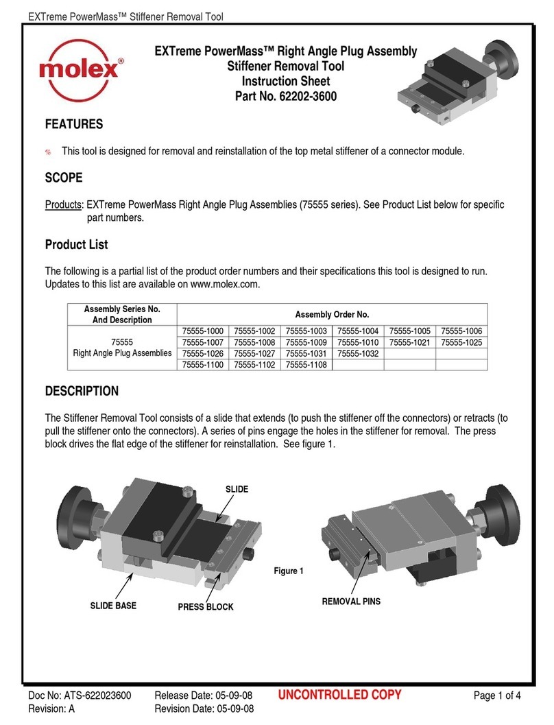
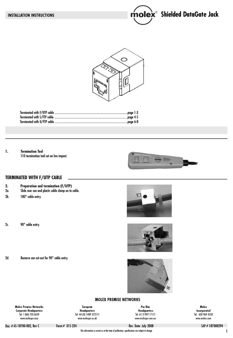
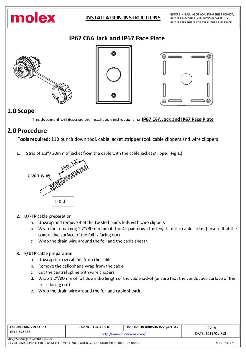
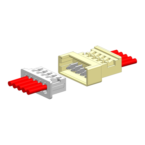
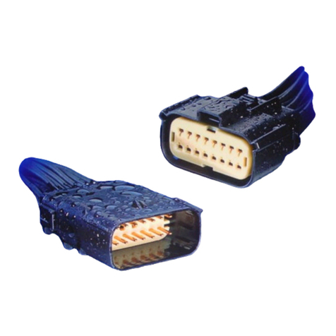
molex Mini50 series User guide

APPLICATION SPECIFICATION
REVISION:
ECR/ECN INFORMATION:
TITLE:
Molex 34 and 38 Way Mini50
Application Specification
SHEET No.
A1
EC No:
114494
1of 22
DATE:
2017 / 03 / 14
DOCUMENT NUMBER:
CREATED / REVISED BY:
CHECKED BY:
APPROVED BY:
AS-34959-001
Tucker Hazel
Jarod Fischer
Ron Bauman
TEMPLATE FILENAME: APPLICATION_SPEC[SIZE_A](V.1).DOC
MOLEX 34 AND 38 WAY MINI50 CONNECTOR SYSTEM APPLICATION SPECIFICATION
1.0 SCOPE: This procedure applies to all part numbers in the 34/38 Way Mini50 series 34958, 34959,
and 34961
Table of Contents
1. Product Scope
2. Product Description
3. Reference Documents
4. Procedure
5. Service Instructions
2.0 PRODUCT DESCRIPTION:
Connector Configurations:
o38 Circuit - 0.50mm
o34 Circuit - 0.50mm/1.20mm Hybrid
3 Polarization Options
Wire Ranges:
o050mm Terminal - 0.13mm2–0.35mm2
o1.20mm Terminal - 0.25mm2–1.0mm2
Utilizes the Molex CTX50 and Tyco 1.2mm MCON Terminal Systems
Receptacles

APPLICATION SPECIFICATION
REVISION:
ECR/ECN INFORMATION:
TITLE:
Molex 34 and 38 Way Mini50
Application Specification
SHEET No.
A1
EC No:
114494
2of 22
DATE:
2017 / 03 / 14
DOCUMENT NUMBER:
CREATED / REVISED BY:
CHECKED BY:
APPROVED BY:
AS-34959-001
Tucker Hazel
Jarod Fischer
Ron Bauman
TEMPLATE FILENAME: APPLICATION_SPEC[SIZE_A](V.1).DOC
Headers
Vertical Right Angle
3.0 REFERENCE DOCUMENTS
Header Series SD-34958-300 Header Packaging PK-31302-070
SD-34961-030 PK-31301-688
Multi-Bay Header SD-34690-0200 Receptacle Packaging PK-31301-538
Series SD-34690-0300
Receptacle Series SD-34959-030 Connector Product Specification PS-34959-001
CTX50 Terminal Sales Drawing SD-560023-002
CTX50 Product Specification PS-560023-001

APPLICATION SPECIFICATION
REVISION:
ECR/ECN INFORMATION:
TITLE:
Molex 34 and 38 Way Mini50
Application Specification
SHEET No.
A1
EC No:
114494
3of 22
DATE:
2017 / 03 / 14
DOCUMENT NUMBER:
CREATED / REVISED BY:
CHECKED BY:
APPROVED BY:
AS-34959-001
Tucker Hazel
Jarod Fischer
Ron Bauman
TEMPLATE FILENAME: APPLICATION_SPEC[SIZE_A](V.1).DOC
4.0 PROCEDURE
A. Connector “As Shipped”
Connector ISL shown in “as shipped” condition (closed). The ISL must be removed and
remain removed until all circuits are loaded.
B. ISL removal procedure
ISL must be removed prior to populating the connector. Insert a small screwdriver (3.0-
4.0mm) into the slot located on the ISL and gently twist the screwdriver to unlock the ISL.
Then remove the ISL completely from the connector housing.
ISL Component

APPLICATION SPECIFICATION
REVISION:
ECR/ECN INFORMATION:
TITLE:
Molex 34 and 38 Way Mini50
Application Specification
SHEET No.
A1
EC No:
114494
4of 22
DATE:
2017 / 03 / 14
DOCUMENT NUMBER:
CREATED / REVISED BY:
CHECKED BY:
APPROVED BY:
AS-34959-001
Tucker Hazel
Jarod Fischer
Ron Bauman
TEMPLATE FILENAME: APPLICATION_SPEC[SIZE_A](V.1).DOC
C. Terminal Installation:
With ISL still removed, orient the terminal to the rear of the connector as shown below. Grip
the wire behind the terminal insulation crimp and insert it through the appropriate circuit
opening. If resistance is encountered, retract the terminal and adjust the angle of insertion.
Continue inserting the terminal until it stops and locks up on the lock finger with an audible
click or tactile feedback. Installing a terminal will have low effort. Improper installation of the
terminals with lead to high effort and wire buckle.
MCON 1.2mm Terminal Installation
CTX50 0.50mm Terminal Insertion
Correct Orientation
180° Mis-orientation
Correct Orientation
180° Mis-orientation

APPLICATION SPECIFICATION
REVISION:
ECR/ECN INFORMATION:
TITLE:
Molex 34 and 38 Way Mini50
Application Specification
SHEET No.
A1
EC No:
114494
5of 22
DATE:
2017 / 03 / 14
DOCUMENT NUMBER:
CREATED / REVISED BY:
CHECKED BY:
APPROVED BY:
AS-34959-001
Tucker Hazel
Jarod Fischer
Ron Bauman
TEMPLATE FILENAME: APPLICATION_SPEC[SIZE_A](V.1).DOC
D. Closing the ISL
Prior to closing the ISL a visual check is recommended to confirm all terminals are fully
seated and in the correct position. Once all terminals are installed, reinstall the ISL and push
until a click or tactile feedback is felt. Install the ISL by pushing on the area as shown below.
Beginning to install the ISL
Just before ISL final lock
ISL after being pushed into final lock
ISL-to-Connector
gap
No gap

APPLICATION SPECIFICATION
REVISION:
ECR/ECN INFORMATION:
TITLE:
Molex 34 and 38 Way Mini50
Application Specification
SHEET No.
A1
EC No:
114494
6of 22
DATE:
2017 / 03 / 14
DOCUMENT NUMBER:
CREATED / REVISED BY:
CHECKED BY:
APPROVED BY:
AS-34959-001
Tucker Hazel
Jarod Fischer
Ron Bauman
TEMPLATE FILENAME: APPLICATION_SPEC[SIZE_A](V.1).DOC
E. Detecting a partially installed terminal
The ISL will not insert fully with a partially installed terminal. The ISL should slide smoothly
through the cavities until it contacts the ISL snap in features. If any resistance is encountered,
remove the ISL from the connector and check to ensure all terminals are seated fully, and
then try to reinstall the ISL.
ISL bows due to
terminal blocking force

APPLICATION SPECIFICATION
REVISION:
ECR/ECN INFORMATION:
TITLE:
Molex 34 and 38 Way Mini50
Application Specification
SHEET No.
A1
EC No:
114494
7of 22
DATE:
2017 / 03 / 14
DOCUMENT NUMBER:
CREATED / REVISED BY:
CHECKED BY:
APPROVED BY:
AS-34959-001
Tucker Hazel
Jarod Fischer
Ron Bauman
TEMPLATE FILENAME: APPLICATION_SPEC[SIZE_A](V.1).DOC
F. Connector Mating
To properly mate the connector, first note and align connector keying and ensure both mating
halves share the same color.
Begin sliding the receptacle connector assembly into the header assembly and press firmly
until you hear an audible click.
If resistance is encountered, confirm the ISL is fully locked and all terminals are fully installed.
A partially installed terminal will not allow the ISL to close.
DO NOT FORCE THE CONNECTOR! DAMAGE TO THE TERMINAL, HEADER AND CONNECTOR ISL WILL OCCUR!
ISL not in final lock
Keying features

APPLICATION SPECIFICATION
REVISION:
ECR/ECN INFORMATION:
TITLE:
Molex 34 and 38 Way Mini50
Application Specification
SHEET No.
A1
EC No:
114494
8of 22
DATE:
2017 / 03 / 14
DOCUMENT NUMBER:
CREATED / REVISED BY:
CHECKED BY:
APPROVED BY:
AS-34959-001
Tucker Hazel
Jarod Fischer
Ron Bauman
TEMPLATE FILENAME: APPLICATION_SPEC[SIZE_A](V.1).DOC
F. Connector Mating: continued
Never mate system at an angle, or with bias. This may cause damage to the header, or
connector
Correct!
Wrong!

APPLICATION SPECIFICATION
REVISION:
ECR/ECN INFORMATION:
TITLE:
Molex 34 and 38 Way Mini50
Application Specification
SHEET No.
A1
EC No:
114494
9of 22
DATE:
2017 / 03 / 14
DOCUMENT NUMBER:
CREATED / REVISED BY:
CHECKED BY:
APPROVED BY:
AS-34959-001
Tucker Hazel
Jarod Fischer
Ron Bauman
TEMPLATE FILENAME: APPLICATION_SPEC[SIZE_A](V.1).DOC
Always push on connector housing while mating. DO NOT push on latch while mating..
Correct!
Wrong!

APPLICATION SPECIFICATION
REVISION:
ECR/ECN INFORMATION:
TITLE:
Molex 34 and 38 Way Mini50
Application Specification
SHEET No.
A1
EC No:
114494
10 of 22
DATE:
2017 / 03 / 14
DOCUMENT NUMBER:
CREATED / REVISED BY:
CHECKED BY:
APPROVED BY:
AS-34959-001
Tucker Hazel
Jarod Fischer
Ron Bauman
TEMPLATE FILENAME: APPLICATION_SPEC[SIZE_A](V.1).DOC
Mating the connector with a CPA
Align the connector and push evenly on the connector body to mate
DO NOT PUSH ON THE CPA DURING THE MATING PROCESS
After mating the connector, push on the CPA to engage

APPLICATION SPECIFICATION
REVISION:
ECR/ECN INFORMATION:
TITLE:
Molex 34 and 38 Way Mini50
Application Specification
SHEET No.
A1
EC No:
114494
11 of 22
DATE:
2017 / 03 / 14
DOCUMENT NUMBER:
CREATED / REVISED BY:
CHECKED BY:
APPROVED BY:
AS-34959-001
Tucker Hazel
Jarod Fischer
Ron Bauman
TEMPLATE FILENAME: APPLICATION_SPEC[SIZE_A](V.1).DOC
Connector with CPA in lock position

APPLICATION SPECIFICATION
REVISION:
ECR/ECN INFORMATION:
TITLE:
Molex 34 and 38 Way Mini50
Application Specification
SHEET No.
A1
EC No:
114494
12 of 22
DATE:
2017 / 03 / 14
DOCUMENT NUMBER:
CREATED / REVISED BY:
CHECKED BY:
APPROVED BY:
AS-34959-001
Tucker Hazel
Jarod Fischer
Ron Bauman
TEMPLATE FILENAME: APPLICATION_SPEC[SIZE_A](V.1).DOC
G. Un-mate procedure
The un-mate the connectors, push connector together to unload the latch system. Then
depress the latch with your thumb (Step 1). Continue to depress the latch, and gently pull
apart connector assemblies
Step 1
Step 2

APPLICATION SPECIFICATION
REVISION:
ECR/ECN INFORMATION:
TITLE:
Molex 34 and 38 Way Mini50
Application Specification
SHEET No.
A1
EC No:
114494
13 of 22
DATE:
2017 / 03 / 14
DOCUMENT NUMBER:
CREATED / REVISED BY:
CHECKED BY:
APPROVED BY:
AS-34959-001
Tucker Hazel
Jarod Fischer
Ron Bauman
TEMPLATE FILENAME: APPLICATION_SPEC[SIZE_A](V.1).DOC
Un-mating a connector with a CPA
Using a small flat tip screwdriver, disengage the CPA by inserting the screwdriver
between the latch and CPA and twisting the screwdriver gently
Push the connector together to unload the latch system. Depress the latch and hold.
Gently pull the connector assemblies apart.

APPLICATION SPECIFICATION
REVISION:
ECR/ECN INFORMATION:
TITLE:
Molex 34 and 38 Way Mini50
Application Specification
SHEET No.
A1
EC No:
114494
14 of 22
DATE:
2017 / 03 / 14
DOCUMENT NUMBER:
CREATED / REVISED BY:
CHECKED BY:
APPROVED BY:
AS-34959-001
Tucker Hazel
Jarod Fischer
Ron Bauman
TEMPLATE FILENAME: APPLICATION_SPEC[SIZE_A](V.1).DOC

APPLICATION SPECIFICATION
REVISION:
ECR/ECN INFORMATION:
TITLE:
Molex 34 and 38 Way Mini50
Application Specification
SHEET No.
A1
EC No:
114494
15 of 22
DATE:
2017 / 03 / 14
DOCUMENT NUMBER:
CREATED / REVISED BY:
CHECKED BY:
APPROVED BY:
AS-34959-001
Tucker Hazel
Jarod Fischer
Ron Bauman
TEMPLATE FILENAME: APPLICATION_SPEC[SIZE_A](V.1).DOC
H. Opening the ISL
Insert a small screwdriver into the slot located on the ISL and gently twist the screwdriver to
unlock the ISL. Then remove the ISL completely from the connector housing.

APPLICATION SPECIFICATION
REVISION:
ECR/ECN INFORMATION:
TITLE:
Molex 34 and 38 Way Mini50
Application Specification
SHEET No.
A1
EC No:
114494
16 of 22
DATE:
2017 / 03 / 14
DOCUMENT NUMBER:
CREATED / REVISED BY:
CHECKED BY:
APPROVED BY:
AS-34959-001
Tucker Hazel
Jarod Fischer
Ron Bauman
TEMPLATE FILENAME: APPLICATION_SPEC[SIZE_A](V.1).DOC
I. Terminal Servicing
For 0.50mm Terminals
With a small thumbtack, gently pry up on the terminal lock finger. Once the lock finger is
released pull on the terminal to remove it from the housing. Connector housing may be
damaged during servicing; inspect the terminal, housing, and lock finger for damage.
Components must be replaced if damaged.
Connector housing can be serviced up to two times, then it must be replaced.
For 1.20mm Terminals
Using Tyco extraction tool 5-1579007-3, insert terminal servicing tool fully into the terminal
servicing cavity like shown below. After confirming that service tool has been inserted fully,
terminal can be removed from the connector.

APPLICATION SPECIFICATION
REVISION:
ECR/ECN INFORMATION:
TITLE:
Molex 34 and 38 Way Mini50
Application Specification
SHEET No.
A1
EC No:
114494
17 of 22
DATE:
2017 / 03 / 14
DOCUMENT NUMBER:
CREATED / REVISED BY:
CHECKED BY:
APPROVED BY:
AS-34959-001
Tucker Hazel
Jarod Fischer
Ron Bauman
TEMPLATE FILENAME: APPLICATION_SPEC[SIZE_A](V.1).DOC
J. Electrical probing, continuity checking
The method of probing used for this product is to use the throat of the terminal. Caution needs
to be taken not to damage the terminals while probing.
4.1 ASSEMBLY INSTRUCTIONS:

APPLICATION SPECIFICATION
REVISION:
ECR/ECN INFORMATION:
TITLE:
Molex 34 and 38 Way Mini50
Application Specification
SHEET No.
A1
EC No:
114494
18 of 22
DATE:
2017 / 03 / 14
DOCUMENT NUMBER:
CREATED / REVISED BY:
CHECKED BY:
APPROVED BY:
AS-34959-001
Tucker Hazel
Jarod Fischer
Ron Bauman
TEMPLATE FILENAME: APPLICATION_SPEC[SIZE_A](V.1).DOC
4.2 DRAWING DETAIL
BELOW ARE VIEWS FROM THE 2 BAY MINI50 STACKED HEADER DRAWING. 2 AND 3 BAY
HEADERS WILL BE COVERED BY THE CORRESPONDING DRAWING.
WHEN LOOKING AT THE FRONT (MATE) SIDE OF THE HEADER IT CAN BE DETERMINED
WHAT HEADER BAY’S ARE IN WHAT LOCATIONS. THE BAY LETTER REFERENCES (BAY ‘A’,
BAY ‘B’, ECT.) ARE LOCATIONS ONLY AND DO NOT REPRESENT ANY PARTICULAR CIRCUIT
SIZE OR KEY OPTION.
THE HEADER ‘BAY ID’ SECTION ON THE CHART CORRESPONDS WITH THE LOCATION ON
THE FRONT VIEW OF THE HEADER.
HEADER MOUNTING STRATEGY:

APPLICATION SPECIFICATION
REVISION:
ECR/ECN INFORMATION:
TITLE:
Molex 34 and 38 Way Mini50
Application Specification
SHEET No.
A1
EC No:
114494
19 of 22
DATE:
2017 / 03 / 14
DOCUMENT NUMBER:
CREATED / REVISED BY:
CHECKED BY:
APPROVED BY:
AS-34959-001
Tucker Hazel
Jarod Fischer
Ron Bauman
TEMPLATE FILENAME: APPLICATION_SPEC[SIZE_A](V.1).DOC
BUILDING OF A PRINTED CIRCUIT
BOARD LAYOUT:
NOTE: THE SAME BAY ID MUST BE USED
FROM THE CHART
1. REFERENCE CHART FOR WHAT CIRCUIT SIZE AND TYPE OF HEADER GO IN EACH ‘BAY’
LOCATION.
2. DETERMINE IF HEADER MUST BE DROP IN CAPABLE
OR IF PRESS FIT IS ACCEPTABLE. PRESS FIT IS RECOMMENDED
AND WILL RETAIN HEADER DURING PROCESSING.
3. USING THE SINGLE HEADER LAYOUTS BELOW BUILD THE PCB LAYOUT OF THE MULTI-BAY

APPLICATION SPECIFICATION
REVISION:
ECR/ECN INFORMATION:
TITLE:
Molex 34 and 38 Way Mini50
Application Specification
SHEET No.
A1
EC No:
114494
20 of 22
DATE:
2017 / 03 / 14
DOCUMENT NUMBER:
CREATED / REVISED BY:
CHECKED BY:
APPROVED BY:
AS-34959-001
Tucker Hazel
Jarod Fischer
Ron Bauman
TEMPLATE FILENAME: APPLICATION_SPEC[SIZE_A](V.1).DOC
HEADER BY SPACING ADJACENT POST HOLES AT 4.08mm.
4. PLACE NECESSARY PCB LAYOUT IN
EACH ‘BAY’ LOCATION AT 4.08mm SPACING.
102CKT –3 BAY HEADER FOOT PRINT –34X34X34
This manual suits for next models
4
Table of contents
Other molex Cables And Connectors manuals
molex
molex Milli-Grid Dual row 87568 Series User manual

molex
molex PicoBlade 1.25 DIP User guide

molex
molex MX150 User guide

molex
molex Micro-Lock Plus 2.0 User guide

molex
molex Shielded DataGate User manual

molex
molex MX123 User manual

molex
molex HDAC .64 Series User manual

molex
molex EXTreme PowerMass 75555 Series User manual
molex
molex IP67 User manual

molex
molex PicoBlade 1.25 W/W User guide