Moog G78K Series Owner's manual

1. INTRODUCTION
This manual provides instructions and procedures necessary to install,
operate and troubleshoot the Moog Inc. Series 78K or G78K series intrinsic
safety protected industrial serovalve. The (G)78K series valves are electrical
equipment for hazardous areas with intrinsic safety or non-incendive protection.
The approved hazardous location markings include:
1G Ex ia IIC/IIB T4 Ga KEMA 02ATEX1015 X
II 3G Ex ec II T3 Gc KEMA 02ATEX1016 X
0344 per ATEX directive 2014/34/EU
Ex ia IIB/IIC T4 Ga IECEx KEM 10.0041X
Ex ec IIC T4 Gc IECEx KEM 10.0041X
per IECEx certification scheme.
The G78K servovalves are also approved by FM, CSA, and TIIS for hazardous
locations. They are intended for directional, position, velocity, pressure and
force control in hydraulic control systems that operate with mineral oil based
fluids. Others on request.
2. OPERATION
The Moog Inc. Series (G)78K Electrohydraulic Servovalve consists
of a polarized electrical torque motor and two stages of hydraulic power
amplification. The motor armature extends into the air gaps of the magnetic flux
circuit and is supported in this position by a flexure tube member. The flexure
tube acts as a seal between the electromagnetic and hydraulic sections of the
valve. The two motor coils surround the armature, one on each side of the
flexure tube.
The flapper of the first stage hydraulic amplifier is rigidly attached to the
midpoint of the armature. The flapper extends through the flexure tube and
passes between two nozzles, creating two variable orifices between the nozzle
tips and the flapper. The pressure controlled by the flapper and nozzle variable
orifice is fed to the end areas of the second stage spool.
The second stage is a conventional four-way spool design in which output
flow from the valve, at a fixed valve pressure drop, is proportional to spool
displacement from the null position. A cantilever feedback spring is fixed to the
flapper and engages a slot at the center of the spool. Displacement of the spool
deflects the feedback spring which creates a force on the armature/flapper
assembly.
Input signal induces a magnetic charge in the armature and causes a
deflection of the armature and flapper. This assembly pivots about the flexure tube
and increases the size of one nozzle orifice and decreases the size of the other.
This action creates a differential pressure from one end of the spool to
the other and results in spool displacement. The spool displacement causes a
force in the feedback wire which opposes the original input signal torque. Spool
movement continues until the feedback wire force equals the input signal force.
ELECTROHYDRAULIC VALVE CUT-AWAY
CAUTION
DISASSEMBLY, MAINTENANCE, OR REPAIR OTHER THAN IN ACCORDANCE WITH THE
INSTRUCTIONS HEREIN OR OTHER SPECIFIC WRITTEN DIRECTIONS FROM MOOG WILL
INVALIDATE MOOG’S OBLIGATIONS UNDER ITS WARRANTY AND YIELD THE INTRINSICALLY
SAFE PROTECTION PERMIT NULL AND VOID.
Upper Polepiece
Flexure Tube
Flapper
Lower Polepiece
Feedback Wire
Inlet Orifice
Magnet
Coil
Armature
Nozzle
Spool
Figure 1 Moog Series (G)78K
Control Port B
Tank
Control Port A
Pressure
Filter
(G)78K Series Installation and
Operation Instruction
Electrohydraulic Servovalve
Intrinsic Safety Protected

3. ELECTRICAL INFORMATION AND INTRINSICALLY
SAFE CIRCUIT SAFETY PARAMETERS
a. A wide choice of coils is available for a variety of rated current
requirements. The torque motor coil leads are attached to the connector
so external connections can provide series, parallel or single coil
operation. The valves are equipped either with an MS type connector or
with pigtail leads for electrical wiring. Refer to installation drawings of the
specific model for details. Servovalve coils should be driven with current
to provide consistency throughout the temperature range.
b. The (G)78K valves are approved for intrinsically safe protection per EN
IEC 60079-0 : 2018, EN 60079-7 : 2015, and EN 60079-11 : 2012 for
ATEX, and IEC 60079-0 : 2017, IEC 60079-7 : 2017, and IEC 60079-11 :
2011 for IECEx. The approved safety parameters are listed in the following
table for all the coils used by (G)78K series. Coil number is marked on
the valve nameplate.
Coil Configuration Marking Ui(MAX) Ii(MAX)
G4220-031 (single, series, parallel) Ex ia IIB T4 12 V 120 mA
G4220-051/098 (single, series, parallel) Ex ia IIB T4 12 V 240 mA
G4221-001 G4220-42 (single) Ex ia IIC T4 16 V 160 mA
G4221-001 G4220-42 (single) Ex ia IIC T4 24.4 V 85 mA
G4220-031 (single, parallel) Ex ia IIC T4 30 V 26 mA
G4220-031 (series) Ex ia IIC T4 30 V 18 mA
G4220-051/098 (single, parallel) Ex ia IIC T4 30 V 19 mA
G4220-051/098 (series) Ex ia IIC T4 30 V 12.7 mA
G4220-042 (single) Ex ia IIC T4 30 V 37 mA
G4220-042 (parallel) Ex ia IIC T4 30 V 20 mA
G4220-042 (series) Ex ia IIC T4 30 V 10 mA
G4221-001 (single) Ex ia IIC T4 30 V 28 mA
c. The (G)78K valves are approved for non-incendive operation for supply
current not to exceed 50 mA dc.
d. When making electric connections to the valve, appropriate measures must
be taken to ensure that locally different earth potential do not result in
excessive ground currents. When barriers are required for the hazardous
location, hazardous area (field) wiring must meet the requirements of
the barrier manufacturer. All barriers must be mounted and installed in
compliance with the barrier manufacturer’s requirements. Twisted pairs of
18-20 gage wire are recommended. If shielded wire is used, connect shield
wire to earth ground only at the barrier strip.
4. SPECIAL CONDITIONS FOR SAFE USE
Because the enclosure of the apparatus is made of aluminum, if it is
mounted in an area where the use of category 1 G apparatus is required, it
must be installed such that even in the event of rare incidents, ignition sources
due to impact and friction sparks are excluded.
When the electrohydraulic servovalve is used in an application for type of
explosion protection intrinsic safety “i”, the appropriate box on the data label
must be scored. When the electrohydraulic servovalve is used in an application
for type of explosion protection “n”, the appropriate box on the data label
must be scored.
After use in an application for type of explosion protection “n”, the
servovalve cannot abe safely used in a intrinsically safe application.
The screwed cable connector may only be disconnected when the circuit
is de-energized or when the location is known to be non-hazardous.
When used at an ambient temperature ≥70°C, heat resistant cable must
be used with a continuous operating temperature in accordance with the
application.
When the electrohydraulic servovalve is used in type of protection “n”
or “ec”, the equipment shall only be used in an area of not more than Pollution
Degree 2, as defined in IEC 60664-1.
The cable gland shall be installed such that impact is not possible.
When the electrohydraulic servovalve is used in type of protection “n”
or “ec”, the user shall provide additional clamping of the cable to ensure that
pulling is not transmitted to the terminations.
5. HYDRAULIC SYSTEM PREPARATION
To prolong servovalve operational life and to reduce hydraulic system
maintenance, it is recommended that the hydraulic fluid be kept at a cleanliness
level of ISO DIS 4406 Code 16/13 maximum, 14/11 recommended. The most
effective filtration scheme incorporates the use of a kidney loop or “off-line”
filtration as one of the major filtration components. The filter for the “off-line”
filtration scheme should be a ß3≥75 filter for maximum effectiveness.
Upon system startup and prior to mounting the servovalve, the entire
hydraulic system should be purged of built-in contaminating particles by an
adequate flushing. The servovalve should be replaced by a flushing manifold and
the hydraulic circuit powered up under conditions of fluid temperature and fluid
velocity reasonably simulating normal operating conditions. New system filters
are installed during the flushing process whenever the pressure drop across the
filter element becomes excessive. The flushing processes should turn over the
fluid in the reservoir between fifty to one hundred times.
To maintain a clean hydraulic system, the filters must be replaced on
a periodic basis. It is best to monitor the pressure drop across the filter
assembly and replace the filter element when the pressure drop becomes
excessive. In addition to other filters that are installed in the hydraulic circuit,
it is recommended that a large capacity, low pressure ß3≥75 filter be installed
in the return line. This filter will increase the interval between filter element
replacements and greatly reduce the system contamination level.
6. INSTALLATION
The Moog (G)78K Series Industrial Servovalve may be mounted in any
position, provided the servovalve pressure, control and tank ports match
respective manifold ports.
The mounting pattern and port location of the servovalve is shown on
Figure 4. The servovalve should be mounted with 5/16-18 x 3 inch long socket
head cap screws. Apply a light film of oil to the screw threads and torque to
120 inch-pounds.
Wire mating connector for desired coil configuration and polarity. Thread
connector to valve.
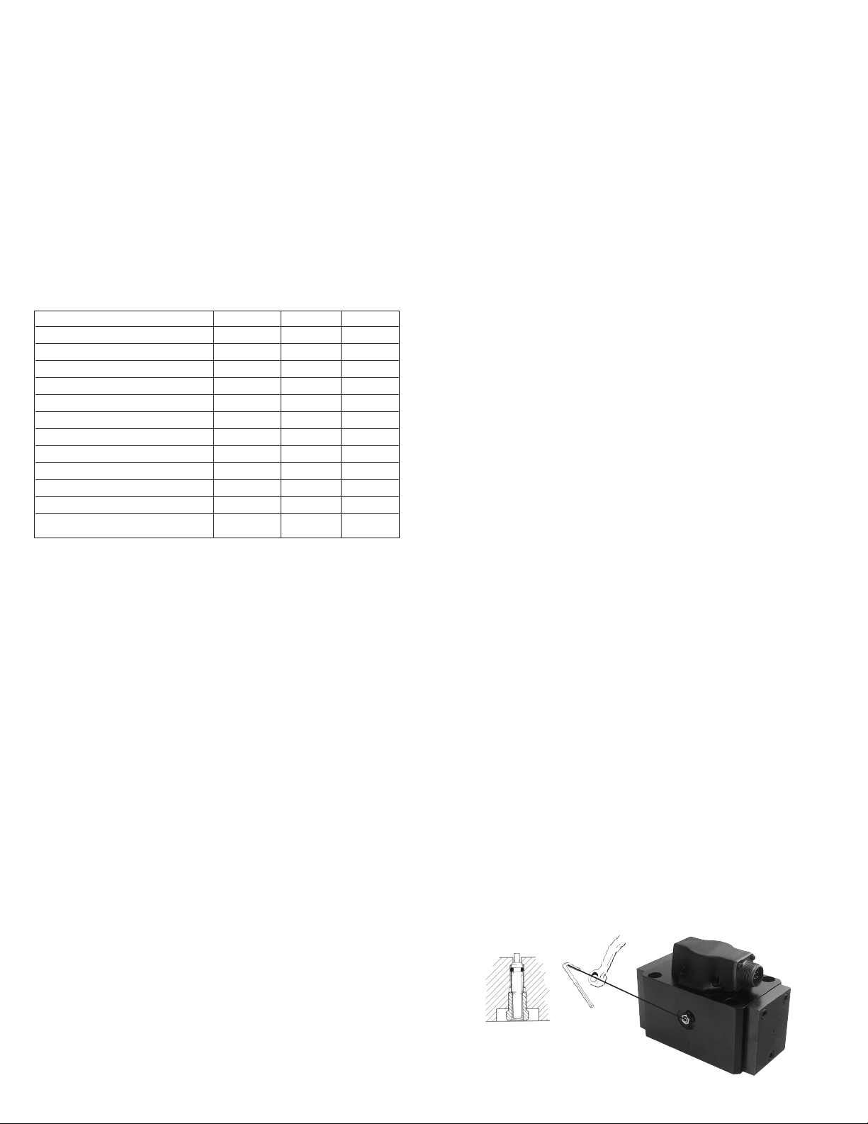
7. MECHANICAL NULL ADJUSTMENT
It is often desirable to adjust the flow null of a servovalve independent of
other system parameters. The “mechanical null adjustment” on the Moog 78
Series servovalve allows at least ±20% adjustment of flow null. The “mechanical
null adjustor” is an eccentric bushing retainer pin located above the tank port
designation on the valve body (see Figure 2) which, when rotated, provides
control of the bushing position. Mechanical feedback elements position the
spool relative to the valve body for a given input signal. Therefore, a movement
of the bushing relative to the body changes the flow null.
Adjustment Procedure
Using a 3/8inch offset box wrench, loosen the self-locking fitting until the
null adjustor pin can be rotated. (This should usually be less than 1/2 turn).
DO NOT remove self-locking fitting. Insert a 3/32 inch Allen wrench in null
adjustor pin. Use the 3/32 Allen wrench to rotate the mechanical null adjustor
pin to obtain desired flow null. Torque self-locking fitting to 57 inch lbs.
Note:
Clockwise rotation of null adjustor pin produces flow from port P to port B.
Figure 2
Mechanical Null Adjustment

Potential Trouble
Servovalve does not follow input command
signal. (Actuator or components are
stationary or creeping slowly.)
High threshold. (Jerky, possible oscillatory
or “hunting” motion in closed loop
system.)
Poor response. (Servovalve output lags
electrical command signal).
High Null Bias. (High input current
required to maintain hydraulic cylinder or
motor stationary.)
Probable Cause
Plugged inlet filter element.
Plugged filter element.
Partially plugged filter element.
1. Incorrect null adjustment
2. Partially plugged filter element.
Remedy
Replace filter element.
Replace filter element and check for dirty
hydraulic fluid in system.
1. Readjust null
2. Replace filter element and check for
dirty hydraulic fluid in system.
9. TROUBLESHOOTING CHART
The following troubleshooting chart list potential troubles encountered, probable causes and remedies.
10. FILTER ASSEMBLY REPLACEMENT
Tools and Equipment
a. Blade screwdriver
b.
3/16 Allen wrench
c. Torque wrench
d. Tweezers
a. Remove six socket head cap screws and lockwashers using a 3/16 inch Allen
wrench. Remove end caps.
b. Remove filter plug and inlet orifice assembly from both sides of body.
Note: 2-56 screw threads into the inlet orifice assembly.
Remove filter. The inlet orifice assemblies are matched to each other and
are therefore interchangeable.
Note: These assemblies seat in body and cannot go through bore
during removal.
c. Remove o-rings from filter plugs and o-rings from inlet orifice assemblies.
d. Visually inspect orifice assemblies for damage or foreign material.
e. Discard o-rings and old filter.
f. Install o-rings on filter plugs and o-rings on inlet orifices.
g. Install filter and inlet orifice assembly, and a filter plug in body. Inlet orifice
assembly pilots into filter.
h. Install end caps on body and install six socket head cap screws and
lockwashers. Torque the screws to 85 inch-pounds.
11. FUNCTIONAL CHECKOUT AND CENTERING
a. Install servovalve on hydraulic system or test fixture, but do not connect
electrical lead.
b. Apply required system pressure to servovalve and visually examine for
evidence of external leakage. If leakage is present and cannot be rectified
by replacing o-rings, remove the discrepant component and return for
repair or replacement.
Note: If the system components are drifting or hardover, adjust
the mechanical null of the servovalve.
c. Connect electrical lead to servovalve and check phasing in accordance
with system requirements.
12. AUTHORIZED REPAIR FACILITIES
If servovalve continues to malfunction after all recommended corrective
action procedures are performed, defective valve should be returned to
Moog for repair. Moog does not authorize any facilities other than Moog or
Moog subsidiaries to repair its servovalves. It is recommended you contact
Moog at (716)652-2000 to locate your closest Moog repair facility. Repair by
an independent (unauthorized) repair house will result in voiding the Moog
warranty and could lead to performance degradation or safety problems.
13. DECLARATION OF MANUFACTURER
An EU Declaration of Conformity according to Council Directive
2014/34/EU is supplied with each servovalve.
Filter Plug
End Cap
Filter Tube
Figure 3 Table 1. Replacement Parts
Part Description Qty. Part Number
(G)78K Series Filter Replacement Kit 1 B52555RK052K001
Base O-Rings 4 -42082-021
End Cap O-Rings (I) 2 -42082-007
Filter Plug O-Rings (I) 2 -42082-012
Inlet Orifice O-Rings (I) 2 -42082-189
Filter Tube (I) 1 C39486-005-060
(I) Included in Filter Replacement Kit.
End Cap
O-Ring
Filter Plug O-Rings
Inlet Orifice Assembly
Inlet Orifice O-Rings
8. GENERAL SERVICING RECOMMENDATIONS
a. Disconnect electrical lead to servovalve.
b. Relieve hydraulic system of residual pressure.
c. Remove servovalve.

Moog Inc., East Aurora, NY 14052-0018
Telephone: 716/652-2000
Fax: 716/687-7910
Toll Free: 1-800-272-MOOG
www.moog.com
TJW/PDF RevF, January 2023, Id. CDS6752-en
2.11
[53.6]
2.87
[72.9]
ELECTRICAL
CONNECTOR
LOCATING PIN
P
2.43
[61.7]
5.75 MAX
[146.1]
.12 DIA
[3.0] .120 ± .025
[3.05 ± 0.64]
[30.15]
[30.15]
[46.02] [46.02]
1.812
1.812
1.187
1.187
.328 [8.33] DIA THRU
CBORE .532 [13.51] DIA
TO DEPTH SHOWN (2.43 REF)
4 MOUNTING HOLES
.008
1.50
[38.1]
4.07
[103.4]
MAX
PIN C
PIN D
PIN B
PIN A
3.04
[77.2]
MAX
3.20
[81.3]
MAX
3.36
[85.3] 2.75
[69.9]
EXTERNAL NULL ADJUST
3/32 IN. HEX SOCKET
M
(G)78K SERIES INSTALLATION AND OPERATION INSTRUCTION NOTES
TYPICAL WIRING SCHEMATIC
The products described herein are subject to change at any time without notice, including, but not limited to, product features, specifications, and designs.
1 Fluid:
Industrial type petroleum base hydraulic
fluid, maintained to ISO DIS 4406 Code
14/11 recommended.
2 Operating Temperature Range:
-20°F [-29°C] to +275°F [+135°C] unless
otherwise specified on nameplate.
3 Valve Phasing:
Flow out port B results when Series coils:
B & C connected, A+, D-;
Parallel coils: A & C connected, B & D
connected; Single coil: A+, B-, or C+, D-.
4 Surface:
Surface to which valve is mounted
requires 63 [ ] finish, flat within .002
[0.05] TIR.
5 Null Adjust:
Flow out port B results with clockwise
rotation of null adjust screw (3/32 hex key).
6 Ports:
0.562 [14.23] diam. c’bored 0.695 (17.65)
I.D. x 0.875 (22.23) O.D.
M
M
2.50
5.00
RETURN PORT
CONTROL PORT B
PRESSURE PORT
CONTROL PORT A
P
63
.98
4 PL
1.96
4.40
2.20
2.375
1.187
1.750
.875
1.812 .812
3.625
.812
1.800
3.600
.002
.625 DIA
4 PLACES
.014 M
VALVE MOUNTS ON THIS
MANIFOLD SURFACE
1.750
.875
4.200
2.100
PORT PER SAE J1926
1.3125-12 UN-2B
DASH 16 STR THD O-RING
BOSS (1.00 TUBE OD REF)
4 PLACES
.156 DIA X .15 MIN DEEP
.010
.344 DIA THRU
CBORE .515 DIA X .50 DP
4 MOUNTING HOLES
.013 M
.3125-18 UNC-2B THD
4 VALVE MTG HOLES
.008
TANK PORT
3
A B C D
DD
Figure 4
4
5
CERTIFICATION CONTROLLED RELATED DOCUMENT
THIS INSTALLATION INSTRUCTION IS CERTIFICATION CONTROLLED.
REVISION SHALL BE APPROVED BY THE MOOG ICD Ex/ATEX
AUTHORIZED PERSON AND MAY REQUIRE APPROVAL BY THE ATEX
NOTIFIED BODY.
APPLICABLE CERTIFICATE(S):
KEMA 02ATEX1015 X
KEMA 02ATEX1016 X
This manual suits for next models
1
Other Moog Protection Device manuals
Popular Protection Device manuals by other brands

VAMP
VAMP 221 Operation and configuration instructions. Technical description

Doka
Doka Xclimb 60 Instructions for assembly and use

SATA
SATA AB1 operating instructions

ALLTEC
ALLTEC DynaShield ADS Series User manual and installation instruction

Veris Industries
Veris Industries XPSD1 installation guide

Bettersafe
Bettersafe Guard Angel installation manual