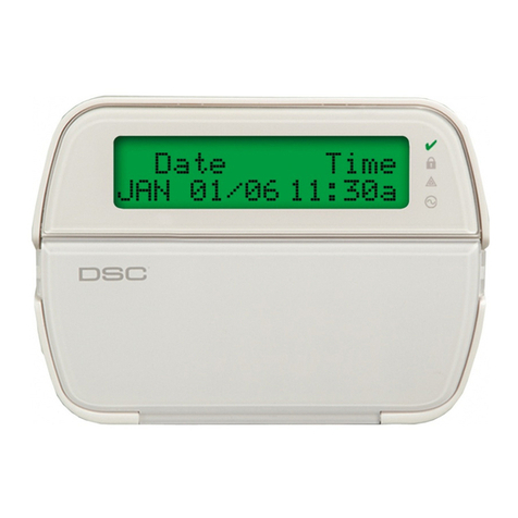
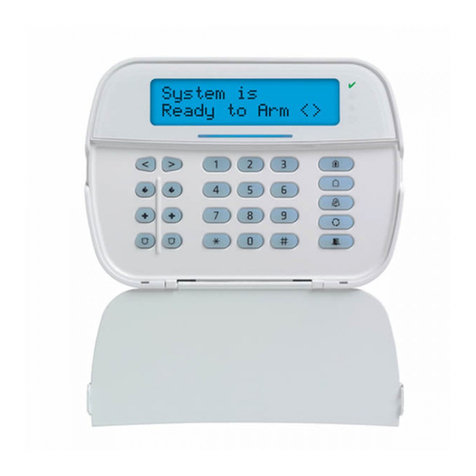
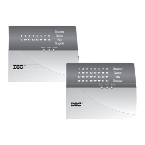
DSC Power 832 User manual

T
M
TM
Installation
Instructions
PC51OO
Version 1.O
S E C U R I T Y S Y S T E M
Please refer to the System Installation Manual for information
on limitations regarding product use and function and informa-
tion on the limitations as to liability of the manufacturer.

FCC COMPLIANCE STATEMENT
CAUTION: Changes or modifications not expressly approved by Digital Security Controls Ltd. could void your
authority to use this equipment.
This equipment has been tested and found to comply with the limits for a Class B digital device, pursuant to Part
15 of the FCC Rules. These limits are designed to provide reasonable protection against harmful interference in a
residential installation. This equipment generates, uses and can radiate radio frequency energy and, if not installed
and used in accordance with the instructions, may cause harmful interference to radio communications. However,
thereisnoguaranteethatinterferencewillnotoccurinaparticularinstallation.Ifthisequipmentdoescauseharmful
interference to radio or television reception, which can be determined by turning the equipment off and on, the user
is encouraged to try to correct the interference by one or more of the following measures:
■Re-orient the receiving antenna.
■Increase the separation between the equipment and receiver.
■Connect the equipment into an outlet on a circuit different from that to which the receiver is connected.
■Consult the dealer or an experienced radio/television technician for help.
The user may find the following booklet prepared by the FCC useful: “How to Identify and Resolve Radio/
Television Interference Problems”. This booklet is available from the U.S. Government Printing Office, Washing-
ton D.C. 20402, Stock # 004-000-00345-4.
Digital Security Controls Ltd. 160 Washburn St., Lockport, NY 14094
This Class [B] digital apparatus complies with Canadian ICES-003.
Cet appareil numérique de la classe [B] est conforme à la norme NMB-003 du Canada.
Limited Warranty
Digital Security Controls Ltd. warrants that for a period of twelve months from the date of purchase, the
product shall be free of defects in materials and workmanship under normal use and that in fulfilment of
any breach of such warranty, Digital Security Controls Ltd. shall, at its option, repair or replace the
defective equipment upon return of the equipment to its factory. This warranty applies only to defects in
parts and workmanship and not to damage incurred in shipping or handling, or damage due to causes
beyond the control of Digital Security Controls Ltd. such as lightning, excessive voltage, mechanical
shock, water damage, or damage arising out of abuse, alteration or improper application of the equip-
ment.
The foregoing warranty shall apply only to the original buyer, and is and shall be in lieu of any and all
other warranties, whether expressed or implied and of all other obligations or liabilities on the part of
Digital Security Controls Ltd. This warranty contains the entire warranty. Digital Security Controls Ltd.
neither assumes, nor authorizes any other person purporting to act on its behalf to modify or to change
this warranty, nor to assume for it any other warranty or liability concerning this product.
In no event shall Digital Security Controls Ltd. be liable for any direct or indirect or consequential
damages, loss of anticipated profits, loss of time or any other losses incurred by the buyer in connection
with the purchase, installation or operation or failure of this product.
WARNING: Digital Security Controls Ltd. recommends that the entire system be completely tested on
a regular basis. However, despite frequent testing, and due to, but not limited to, criminal tampering or
electrical disruption, it is possible for this product to fail to perform as expected.

1
Overview
S E C T I O N 1
1.1 Specifications
PC5100 2-Wire Addressable Device Interface Module
• The PC5100 is an interface module for the PC5010 and PC5015
alarm control panels. The module is used to connect 2-wire
addressable devices to the Power832 Security System.
• Current draw: 40mA
• Addressable loop maximum current draw: 170mA
• Up to 32 2-wire addressable devices can be added to the system
• Compatiblilty PC5010 v2.x or higher; PC5015 v2.x or higher.
Addressable Multiplex Loop (AML) Devices
All addressable series devices use a 2-wire connection for power and
to communicate with the control panel. This simplifies wiring and
permits fast and efficient installations.
WARNING: Connect only DSC Addressable Series devices to the
addressable loop connections. Connection of ANY other type of
device will impair operation. Any devices other than Addressable
Series devices which require power to operate must be powered
separately.
*Always use the Standby Current Draw when calculating maximum
wire run lengths.
ADDRESSABLE DEVICE CURRENT LOADING
Device Description Standby* Alarm Test
AMS-220/AMS-220T Smoke Detector 0.8 mA 1.5 mA 1.5 mA
AMB-300 Motion Detector 2.5 mA 2.5 mA 5.0 mA
AMB-500 Ceiling Mount Motion Detector 2.5 mA 2.5 mA 5.0 mA
AMB-600 Pet Immune Motion Detector 3.5 mA 3.5 mA 6.5 mA
AMA-100 Glassbreak Detector 3.5 mA 3.5 mA 5.5 mA
AMP-700/AMP-701 Contact 0.8 mA 0.8 mA 0.8 mA

2
Getting Started
S E C T I O N 2
2.1 Connecting the PC5100 Interface Module
Remove all power from the control panel before connecting
any module to the system.
Connect the PC5100 to the PC5010/5015 Keybus by inserting the red,
black, yellow and green Keybus wires into their corresponding termi-
nals.
If the PC5100 is not located within the main cabinet, a PC5204
power supply must be used to power the module, as in the
diagram below.
After wiring is complete, add power back to the PC5010/PC5015.
The system will detect the new module and it will be supervised.
2.2 Calculating Current Draw
Up to 32 addressable devices can be connected to the PC5100.
However, a maximum of 170mA of current can be used on the address-
able loop. Calculate how much current your selection of devices will
require by completing the following table:

G E T T I N G S T A R T E D
3
2.3 Connecting 2-Wire AML Devices
The 2-wire addressable devices are connected to the STR+ and STR-
terminals on the PC5100. All devices can be home-run, t-tapped or
connected in a daisy chain. Please refer to the diagram below:
The wiring length of each addressable loop is restricted to the following
distances, depending on the amount of current required (see Section
2.2 “Calculating Current Draw”). Consult the wiring chart on the next
page.
For longer wire runs, you can split
the addressable devices onto two
or more loops from the STR termi-
nals. For example, 32 AMB-300
detectors (2.5mA each) take 80mA
total. In one 18AWG wire run, this
would allow a maximum length of
720 feet (220 m). If you split the 32
devices into two wire runs of 16
detectors each, using 18AWG wire,
each wire run could be 1736 feet
(529 m) long. See the diagram on
the right.
Model # Description Quantity x
Max. Device
Current Draw
(in standby mode)
Total
Current
AMS-220 Smoke Detector x 0.8 mA =
AMB-300 PIR Detector x 2.5 mA =
AMB-500 Ceiling Mount PIR x 2.5 mA =
AMB-600 Dual PIR Detector x 3.5 mA =
AMA-100 Glass-break Detector x 3.5 mA =
AMP-700 Magnetic Door/Window Contact x 0.8 mA =
AMP-701 Contact Input Module x 0.8 mA =
Total Current Draw (Maximum 170 mA) =

G E T T I N G S T A R T E D
4
Not more than four
24AWG conductors
should be connected to a
single terminal as wire
bulk may cause improper
operation.
All devices must be enrolled as
individual zones on the system
by entering their serial numbers
(see section 3.2 “Enrolling
Devices”).
Loop Current vs. Wiring Distance
Total loop
current (mA) 22 AWG
distance (ft/m) 18 AWG
distance (ft/m)
10 2880/878 5143/1568
20 1620/494 3645/1111
30 1010/308 2520/768
40 771/235 1736/529
50 600/183 1250/381
60 500/152 980/298
70 400/122 800/244
80 321/98 720/220
90 250/76 500/152
100 200/61 310/95
110 165/50 220/67
120 135/41 155/47
130 115/35 130/39
140 106/32 126/38
150 100/30 124/37
160 98/29 122/36
170 96/28 120/35
If any of the system keypads indicate a PC5100 module tamper,
or if any zones show as open, or show a zone fault, there may
be a short on the AML loop.The PC5100 module and zones will
not be restored until the short is corrected - remove power
from the system and re-check the zone wiring.
2.4 Connecting the PC5100 Tamper
The PC5100 has a built-in tamper switch (SW1). If an external tamper
switch is being used, connect the switch according to the following
diagram.
If neither the built-in tamper nor an external switch is being
used, you must short the TAM and BLK terminals. If you do not
make this connection, a trouble condition will be indicated.

5
Programming the PC5100
S E C T I O N 3
3.1 How to Program
You can program the PC5100 by entering installer’s programming
mode ([Q] [8] [Installer’s code]) at any system keypad.
All PC5100 programming is in programming section [805] (see page 8).
Ensure that you have double checked each entry for all device
serial number sections. If you have entered data which was not
accepted, the section will not change from the previous
settings and device serial numbers will revert to [00000].
3.2 Enrolling Devices
To enroll AML devices:
1. At a system keypad, enter [Q][8][Installer’s code] to go to the
installer’s programming section.
2. Enter programming section [805].
3. Enter the 2-digit number corresponding to the zone the device is to
occupy ([01] to [32]).
NOTE: You cannot enroll more than one device to a zone.
If you install AML devices on zones programmed as interior
and delay zone types, the delay zones must have a lower zone
number than the interior zones. For example, if zone number
[04] is a delay zone, interior zones that use AML devices can
only be installed on zones [05] or higher. If you program an
AML delay zone with a higher number than AML interior zones,
the system may detect a violation on the interior zone before
the delay zone is triggered, causing a false alarm.
4. Enter the device’s serial number. The entry
must
be five digits.
5. The device is now enrolled on the system. Record the serial number
and the assigned zone number in the programming worksheets in
the back of this manual.
6. Continue with steps 3 - 5 until you have enrolled all devices.
7. To exit press [#].
Once you have enrolled all the AML devices, you should
program the Panel Key. See section 3.7 for more information.
3.3 Zone Programming
The AML devices will not work properly until you complete the zone and
partition programming. Select a zone definition for each used zone in
programming sections [001] – [004].
You must also enable the wireless/AML zone attribute for each zone
that has been assigned to an AML device. To do this, turn ON option 8
in the appropriate programming section (one or more of sections [101]
– [132]). See your PC5010 or PC5015
Installation Manual
for more
information.
To ensure proper operation, use zone definitions (87) and (88) for both
delayed and standard fire zones on the addressable loop.

P R O G R A M M I N G T H E P C 5 1 0 0
6
3.4 Module and Device Supervision
To confirm that the panel is supervising the PC5100, enter section
[903]. If the PC5100 is being supervised, on LED keypads light 15 will
be on, and on LCD keypads the message “PC5100” will be displayed.
Devices are supervised as zones. The level of supervision for AML
devices is determined by the type of zone supervision that was se-
lected for the PC5010/5015 (i.e. normally closed, single end of line, or
double end of line supervision).
For more information, please refer to your PC5010 or PC5015
Installa-
tion Manual
.
3.5 Removing Devices
Before removing devices from the system, you must delete their serial
numbers. To remove a 2-wire addressable device from the system,
perform the steps outlined in Section 3.2. Enter [00000] for the serial
number of the device you wish to remove.
You may need to power down the panel to clear troubles which
could be caused by deleted devices.
3.6 Replacing Devices
In order to replace an AML device, you must first remove the old
device, as described in section 3.5, above. Then, enroll the new device
as described in section 3.2.
3.7 Programming Section Descriptions
Sections [01] - [32]: Zone Serial Numbers
These sections are for enrolling the serial numbers of each 2-wire
addressable device on the system. See Section 3.2 for details.
Section [97]: Special Functions
Option 1: Walk test light ON. Turn on this option to enable the walk
test LED on all motion and glassbreak detectors. If a device is working,
its LED will turn on when it is tested.
This option does not turn on the walk test - only the walk test
LEDs.To walk test the system, follow the instructions in the
Walk Test section of the PC5010 or PC5015 Installation Manual.
• To test the motion detectors, create motion in front of each device. If
the LED turns on, the device is working.
• To test the glassbreak detectors, you will also need to turn on option
4 (Glassbreak Test ON). See the
AMA-100 Installation Instruction
sheet for testing instructions.
Once the walk test has been completed, re-enter Section [97] and turn
option [1] OFF.
Option 2: Smoke test on installer exit. Turn on this option to enable
the smoke test for all AML smoke detectors. The PC5100 will begin the
test after you exit from Installer’s Programming. The PC5100 tests each
smoke detector by:
• turning on the test output of each detector, and then checking for an
alarm state on each detector

P R O G R A M M I N G T H E P C 5 1 0 0
7
• turning off the test output and checking for an alarm restore state on
each detector.
If the PC5100 module does not receive an alarm signal from a smoke
detector, there will be a trouble on that zone when the test is over. The
trouble will only be restored when the next smoke test is performed and
the detector passes the test. If the PC5100 module does not receive a
restore signal from a smoke detector, there will be an alarm on that
zone when the smoke test is over. The alarm will be restored once the
zone has been restored.
After you turn on this test, do not enter Installer’s Programming for at
least 60 seconds. The PC5100 will turn off the option once the test is
complete.
See your
AMS-220 Installation Instruction
sheet for more information on
testing AML smoke detectors.
If a smoke alarm occurs during the smoke test, the zone will be
placed into the alarm state once the test has been completed.
Option 3: 24-hour smoke test.
If this option is turned on, the panel will
perform the smoke test as described in option 4, above, every day at
11:00 pm.
Option 4: Glassbreak test ON. Turn this option on to test AMA-100
devices with the AFT-100. After you have turned this option on, follow
the instructions in the Walk Test section of the PC5010 or PC5015
Installation Manual
. See the
AMA-100 Installation Instruction
sheet for
testing instructions.
The AMA-100 will not respnd to the AFT-100 unless this option is turned
on. Turn this option OFF when you are done testing the AMA-100 devices.
Section [98]: Panel Key
IMPORTANT:We strongly recommend that the panel key be
programmed to ensure the security of the system.
The Panel Key is a 2-digit code which acts as a security lock for the
addressable detectors. Once you have enrolled all addressable zones
you must change the panel key from the default “00” to another 2-digit
number (01-FF). When the panel key is changed, the panel will broad-
cast the new code to each addressable device.
Section [99]: Module Default
To return the module to its factory default settings, enter section [99],
then enter [55].
Before you can continue programming the PC5100 module,
you must exit (press [#] twice), and then re-enter installer’s
programming (enter [*][8][Installer’s Code]).
3.8 Testing the System
To verify that each device is working as intended, you should perform a
walk test once all devices have been installed. To perform a walk test,
follow the instructions in section 3.7 (Option 1: Walk Test Light ON),
and in your PC5010 or PC5015
Installation Manual
.
You should also perform a test of the smoke detectors as described in
section 3.7 (Option 2: Smoke test on installer exit).

8
[805] PC5100 Expansion Programming
Zone Serial Numbers
Default for each section = 00000 (5-digit decimal entry required)
[01] Zone 1 l_____l
_____l
_____l
_____l
_____l
[02] Zone 2 l_____l
_____l
_____l
_____l
_____l
[03] Zone 3 l_____l
_____l
_____l
_____l
_____l
[04] Zone 4 l_____l
_____l
_____l
_____l
_____l
[05] Zone 5 l_____l
_____l
_____l
_____l
_____l
[06] Zone 6 l_____l
_____l
_____l
_____l
_____l
[07] Zone 7 l_____l
_____l
_____l
_____l
_____l
[08] Zone 8 l_____l
_____l
_____l
_____l
_____l
[09] Zone 9 l_____l
_____l
_____l
_____l
_____l
[10] Zone 10 l_____l
_____l
_____l
_____l
_____l
[11] Zone 11 l_____l
_____l
_____l
_____l
_____l
[12] Zone 12 l_____l
_____l
_____l
_____l
_____l
[13] Zone 13 l_____l
_____l
_____l
_____l
_____l
[14] Zone 14 l_____l
_____l
_____l
_____l
_____l
[15] Zone 15 l_____l
_____l
_____l
_____l
_____l
[16] Zone 16 l_____l
_____l
_____l
_____l
_____l
[17] Zone 17 l_____l_____l
_____l
_____l
_____l
[18] Zone 18 l_____l_____l
_____l
_____l
_____l
[19] Zone 19 l_____l_____l
_____l
_____l
_____l
[20] Zone 20 l_____l_____l
_____l
_____l
_____l
[21] Zone 21 l_____l_____l
_____l
_____l
_____l
[22] Zone 22 l_____l_____l
_____l
_____l
_____l
[23] Zone 23 l_____l_____l
_____l
_____l
_____l
[24] Zone 24 l_____l_____l
_____l
_____l
_____l
[25] Zone 25 l_____l_____l
_____l
_____l
_____l
[26] Zone 26 l_____l_____l
_____l
_____l
_____l
[27] Zone 27 l_____l_____l
_____l
_____l
_____l
[28] Zone 28 l_____l_____l
_____l
_____l
_____l
[29] Zone 29 l_____l_____l
_____l
_____l
_____l
[30] Zone 30 l_____l_____l
_____l
_____l
_____l
[31] Zone 31 l_____l_____l
_____l
_____l
_____l
[32] Zone 32 l_____l_____l
_____l
_____l
_____l
Programming Worksheets
S E C T I O N 4
[97] Special Functions Options (1-3)
Default = OFF Option ON Option OFF
l________lOption 1 Walk test LED ON Walk test LED OFF
l________lOption 2 Smoke test on installer exit Smoke test OFF
l________lOption 3 24-hour smoke test ON 24-hour smoke test OFF
l________lOption 4 Glassbreak test mode ON Glassbreak test mode OFF
l________lOption 5-8 Not used
[98] Panel Key (2-digit hexidecimal entry)
l_____l
_____l
[99] PC5100 Module Default
Enter [55] in this location to return the PC5100 to its default settings.

9
Guidelines for Locating Smoke Detectors
A P P E N D I X A
Experience has shown that all hostile fires in family living units generate smoke to a
greater or lesser extent. Experiments using typical fires in family living units indicate that
detectable quantities of smoke precede detectable levels of heat in most cases. In
existing homes, the 1993 edition of NFPA 72 requires that a smoke detector be installed
outside each sleeping area and on each additional story of the family unit.
The following information is for general guidance only and it is recommended that the
1993 edition of NFPA 72 (National Fire Protection Association, One Batterymarch
Park, Quincy,MA 02269) be consulted and that the smoke detector manufacturer’s
literature be used for detailed installation instructions.
It is recommended that additional smoke detectors beyond those required be installed
for increased protection. The added areas include: basement, bedrooms, dining rooms,
furnace room, utility room and hallways not protected by the required detectors.
Figure 1: A smoke detector should be located
between the sleeping area and the rest of the
family unit.
Figure 3: A smoke detector should be located on
each story of the living unit.
Figure 2: In family living units with more than one
sleeping area, a smoke detector should be lo-
cated to protect each sleeping area. Figure 4: Smoke Detector Mounting - ‘Dead’
AirSpace. The smoke from a fire generally rises
to the ceiling, spreads out across the ceiling
surface and begins to bank down from the ceil-
ing. The corner where the ceiling and wall meet
is an air space into which the smoke may have
difficulty penetrating. In most fires, this “dead”
air space measures about 4 in. (0.1m) along the
ceiling from the corner and about 4 in. (0.1m)
down the wall as shown in Figure 4. Detectors
should not be placed in the ‘dead’ air space.
Family Room Bedroom
Living
Room
Dining
Room
Kitchen
Bedroom Bedroom
NEVER
HERE
Acceptable
here
Top of detector
acceptable here
12"
(0.3m)
Max.
4"
(0.1m)
Max.
4"
(0.1m)
Ceiling
Wall
NOTE: Measurements shown are to
the closest edge of the detector.
Bedroom Bedroom
Basement
Living
Room Dining
Room
Bedroom Bedroom
Bedroom
Living RoomKitchen

© 1999 Digital Security Controls Ltd.
1645 Flint Road, Downsview, Ontario, Canada M3J 2J6
Tel. (416) 665-8460 • Fax (416) 665-7498 • Tech. Line 1-800-387-3630 • www.dscgrp.com
Printed in Canada 29003139 R001
Security Products
TM
Other manuals for Power 832
5
This manual suits for next models
1
Table of contents
Other DSC Security System manuals
Popular Security System manuals by other brands

Smanos
Smanos SS2800 user manual

Busch-Jaeger
Busch-Jaeger Busch-Infoline 1531 U operating instructions

Shuttle
Shuttle D1416 user guide

Trend Micro
Trend Micro txOne networks EdgeIPS IPS-102-BP-TM Quick setup guide

Risco
Risco LightSYS Quick Programming

Veermount Technology
Veermount Technology TeleHawk 3 installation manual