4 The Interface Solution Experts
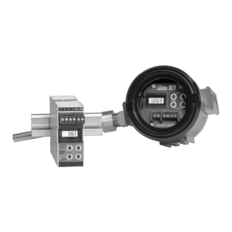
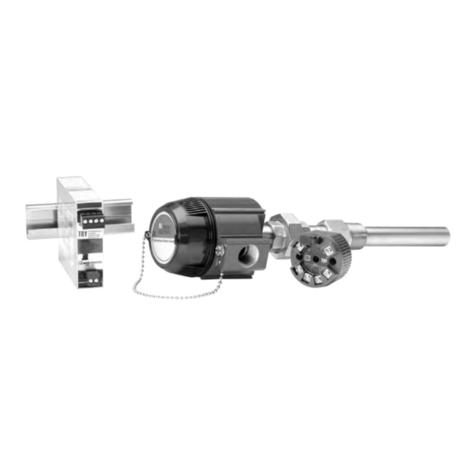
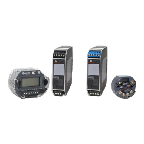
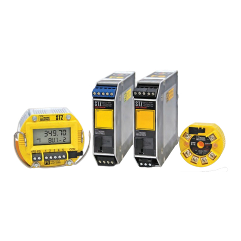
THZ &TDZ
AdditionalParts
Every THZ or TDZ order comes with one copy of our
Configuration Software on a 3½-inch floppy disk
(Windows®95, 98, and NT 4.0 compatible). The
HART RS-232 Modem and the HART Communicator
must be purchased separately. However, the THZ
and TDZ transmitters work with any standard, third-
party communicator, such as the Fisher-Rosemount
Model 275.
IntelligentPCConfigurationSoftware
(One copy comes free with each order)
HART-to-RS232SmartInterfaceCable
with HART Modem
PartNumber
235-75120-05
PartNumber
803-048-26
Additional accessories are available as follows:
OrderingInformation
Unit
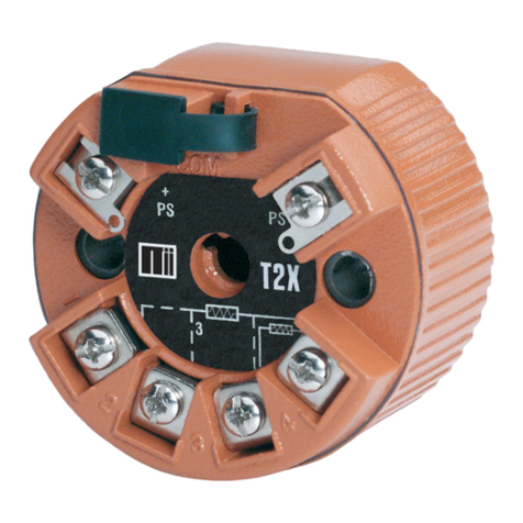
THZ
SmartHART
Temperature
Transmitter
THZ
(DHHousing)
Dual-
Compartment
SmartHART
Temperature
Transmitter
withDisplay
TDZ
SmartHART
Temperature
Transmitter
with
Display
Input
PRG
Programmable
withstandard
HART
Communicator,
HART-based
control system,
orMoore
Industries’
PC-based
Configuration
Software
Output
4-20MA
Scaleable
tonarrower
ranges
Power
12-42DC
12-30DC
for I.S.
applica-
tions
Housing
DIN DIN-style aluminum housing mounts on 32mm G-type (EN50035) and
35mmTopHat(EN50022)
HPP Hockey-puck housing for mounting in connection heads
LH1NS LH1 head with two entry ports: ½-inch NPT conduit and process–black
PBT polyester cover
LH1MS LH1 head with two entry ports: M20 cable and ½-inch NPT
process–black PBT polyester cover
LH1CS LH1 head with two entry ports: M20 cable and G½ (BSP)
process–black PBT polyester cover
LH2NS Explosion-Proof LH2 head with two entry ports: ½-inch NPT conduit
and process–black metal cover
LH2MS Explosion-Proof LH2 head with two entry ports: M20 cable and ½-inch
NPT process–black metal cover
CH6 Polypropyleneconnectorhead
DH THZ [DH] replacement transmitter with no enclosure
DH2NG THZ [DH] enclosed in a 2-Hub, dual-compartment enclosure with two,
½-inch NPT entry ports and a glass cover
DH2TG THZ [DH] enclosed in a 2-Hub, dual-compartment enclosure with two,
¾-inch NPT entry ports and a glass cover
DH2MG THZ [DH] enclosed in a 2-Hub, dual-compartment enclosure with two,
M20 x 1.5 entry ports and a glass cover
BH2NG 2-Hub,explosion-proof enclosure with two, ½-inch NPT entry ports
and a glass cover
BH2TG 2-Hub, explosion-proof enclosure with two, ¾-inch NPT entry ports
and a glass cover
BH2MG 2-Hub, explosion-proof enclosure with two, M20 x 1.5 NPT entry ports
and a glass cover
BH3NG 3-Hub,explosion-proof enclosure with three, ½-inch NPT entry ports
BH3TG 3-Hub,explosion-proofenclosure with two, ¾-inch side-entryNPT
ports, one ½-inch bottom port, and a glass cover
BH3MG 3-Hub, explosion-proof enclosure with two, M20 x 1.5 side-entry ports,
one ½-inch bottom-entry port, and a glass cover
D2LC 2-Hub, low base, clear cover, NEMA 4X (IP66) enclosure
HP Hockey-puck housing and spring clips
DNSnap-in mounting for HP case on TS-32 DIN-rail
FL Mounting flanges on HP suitable for relay track or screw mounting
FLD Mounting flanges on HP suitable for 3½” relay track mounting
Psuffix indicates enclosure comes equipped with base and U-bolts for mounting on a 2-inch pipe
(i.e. BH2NGP)
To order, specify: Unit / Input / Output / Power [Housing]
ModelNumberExample: THZ / PRG / 4-20MA / 12-42DC [DH2NG]
