4 The Interface Solution Experts
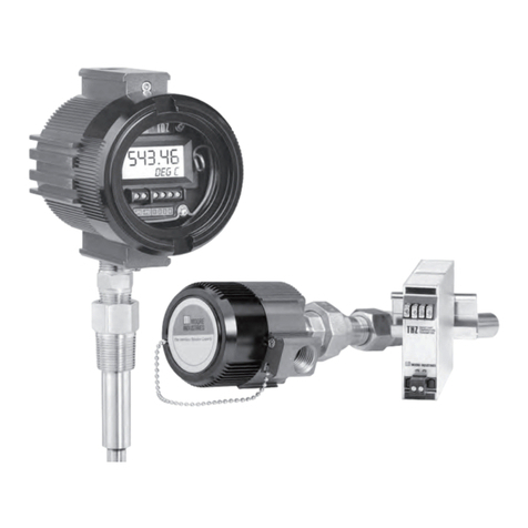
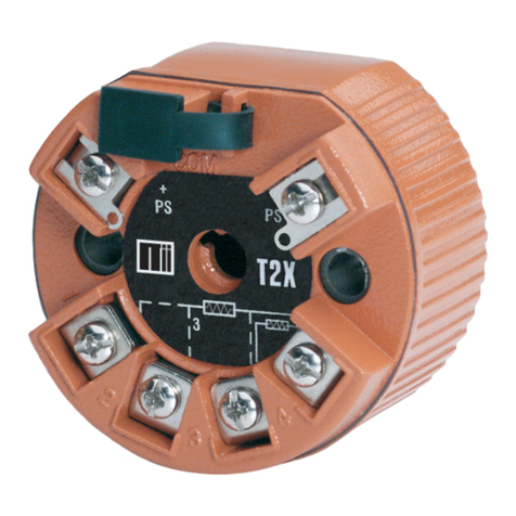
TRZ
Unit Input Output Power Housing
TRZ
Smart
HART
Temperature
Transmitter
PRG
Programmable
with standard
HART
Communicator,
HART-based
control system,
or Moore
Industries'
PC-based
Configuration
Software
(included)
4-20MA
output with
HART digital
data
superimposed
12-28Vdc
(loop-powered
from output
side)
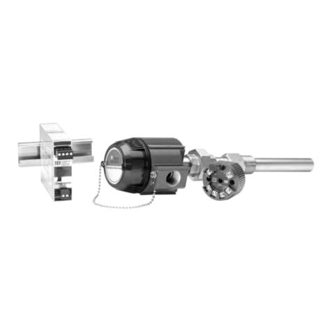
HPP Hockey-puck housing for mounting in standard connection heads
LH1NS* Connection head (FM approved, NEMA 4X, IP66) with two
entry ports: ½-inch NPT cable and process—black PBT polyester
cover
LH1NA* Connection head (FM approved, NEMA 4X, IP66) with two
entry ports: ½-inch NPT cable and process—black aluminum cover
LH1MS* Connection head (FM approved, NEMA 4X, IP66) with two
entry ports: M20 cable and ½-inch NPT process—black PBT
polyester cover
LH1CS* Connection head with two entry ports: M20 cable and G½
(BSP) process—black PBT polyester cover
LH2NS*‡ Explosion-proof connection head (FM approved, Class I,
Div 1, Groups A**,B,C,D; Class II, Groups E,F,G; Class III) with two
entry ports: ½-inch NPT cable and process—black metal cover
LH2MS*‡ Explosion-proof connection head (FM approved, Class I,
Div 1, Groups A**,B,C,D; Class II, Groups E,F,G; Class III) with two
entry ports: M20 cable and ½-inch NPT process—black metal cover
CH6 Plastic polypropilene connection head
* For alternate cover color, replace the fifth designator in the LH1 model number with
appropriate letter from below (i.e. LH1NG): C= Clear (LH1 only), B= Blue, R= Red,
Y= Yellow, G= Green.
NOTE: Add "P" suffix to any LH or CH housing for 2-inch pipe mounting hardware (e.g.,
LH1NSP).
** For Group A (only) all conduit must be sealed within 18 inches.
‡LH2 Explosion-proof certification carries 60°C (140°F) max ambient
temperature restriction.
Other connection heads, cabinets, and enclosures are also available.
Ask your Interface Solutions Expert for details.
When ordering specify: Unit / Input / Output / Power [Housing]
Model Number Example: TRZ / PRG / 4-20MA / 12-28DC [LH1NSP]
Ordering Information
ModelandSerialNumbers
Moore Industries uses a system of model and serial
numbers to keep track of all of the information on
every unit it sells and services. If a problem occurs
with a TRZ, check for a tag affixed to the unit listing
these numbers. Supply the Customer Support repre-
sentative with this information when calling.
If additional units are needed, use the information
printed in bold text in the table above to “build” a
model number for the type of transmitter required.
AdditionalParts
Each TRZ order comes with one copy of our Configu-
ration Software on a 3½-inch floppy disk (Windows
‘95, ‘98, and Windows NT compatible). A HART Com-
municator is not included with the TRZ. The TRZ unit
will work with any standard, third-party unit, such as
the Fisher-Rosemount model 275.
TRZIntelligentPCConfigurationSoftware
(One copy comes free with each order)
HART-to-RS232SmartInterfaceCable
withHART Modem
PartNumber
235-75120-03
PartNumber
803-048-26
PC-ProgrammingKit
Includes one copy of the TRZ Intelligent PC
ConfigurationSoftwareandoneHART-to-RS232
CablewithHARTModem.
PartNumber
235-829-01
Additional accessories are available as follows:
