Page 1
SPT
The Interface Solution Experts
Introduction
This is the Users’ Manual for Moore Industries’ SPT,
Site-Programmable Temperature Transmitter. The SPT
accepts inputs from thermocouples, RTDs, or millivolt
or resistance (ý) sources in a host of sensor types and
connection schemes. It provides isolated, linearized (or,
selectably, non-linearized), process-ready output in
several common ranges, and can be readily switched to
operate as either a current or voltage source, or as a
current sink.
The SPT’s configurability makes it practical for use as
a “generic” transmitter — a single unit that can be
stocked, and set on-site to fulfill the requirements of
several different signal conditioning applications within
a process or plant. SPTs can also serve as replace-
ments for installed transmitters from other manufactur-
ers.
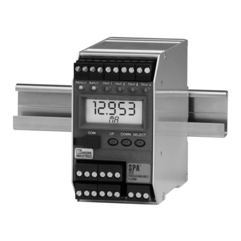
Unit setup is quick, intuitive, and flexible. Most opera-
tion settings can be viewed and/or changed using push
buttons and a series of simple menus displayed on the
unit’s front panel LCD. Source/sink output settings, as
well as failsafe or non-failsafe alarm function (with the
optional alarm output) are controlled by a set of DIP
switches that are located with a security jumper inside
the housing behind a sliding panel. This makes disas-
sembly of the unit unnecessary.
The following guidelines are used throughout the
manual:
WARNING
– Hazardous procedure or condition that
could injure the operator.
Caution
– Hazardous procedure or condition that could
damage or destroy the unit.
Note
– Information that is helpful for a procedure, con-
dition, or operation of the unit.
Total Sensor Diagnostics
The SPT incorporates a patented input circuit that elimi-
nates much of the time consuming, trial-and-error work
of troubleshooting sensor networks. Total Sensor Di-
agnostics (TSD) continuously monitors the status of both
the input sensor (or sensors) and wiring.
If a wire breaks, or the sensor fails, a front panel LED
changes color to flag the problem, and the LCD displays
a message telling
where
the failure has occurred. In
multiple RTD or direct ohms input applications, the SPT
messages indicate which sensor has failed, or if a wire
is broken.
These diagnostic messages allow the user to distinguish
between failures of one of the wires or in the sensor itself.
In multiple sensor applications, the SPT can even dif-
ferentiate between one wire and another.
In addition to these indications, the C option enables
the SPT to provide a contact-closure alarm output that
trips in the event of a sensor failure.
Universal Mounting Capability
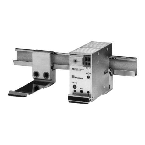
The unit is housed in a “universal” DIN case that can be
mounted on both 32mm G-type (EN50035) and 35mm
Top Hat (EN50022) DIN rail. The Installation section of
this manual gives unit dimensions.
Programmable Features
No hand-held configurator or sophisticated bench equip-
ment is needed to get the SPT up and running. Unit
control is done with four push buttons on the front panel.
The standard SPT handles a variety of inputs, outputs,
and multi-sensor applications:
•Inputs – RTD type and number of wires, T/C
type, direct mV or resistance (ohms); reference
junction compensation on/off, linearization on/off.
• Outputs – 4-20mA (source or sink), or 1-5V,
configurable to drive upscale or downscale on
sensor failure. Optional SPDT relay is
configurable as failsafe or non-failsafe, with high
or low alarm function.
• Differential or Averaging – Multiple sensors
(direct ý or RTDs) can be connected to provide
output based on differential inputs, or the
averaging of two or more sensors.
• Smart-Ranging – An innovative operating
feature allows the user to “program in” zero and
full scale values. This eliminates the need for
elaborate calibration setups.
