Mopar CHRYSLER 300C User manual

1
REMOTESTART
CHRYSLER300C/DODGECHARGER
Dec01,2009K6860933
4280189

2
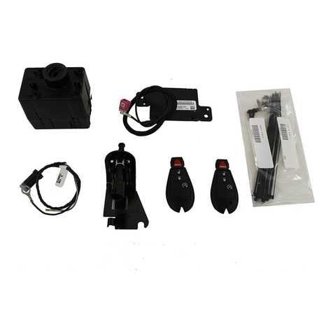
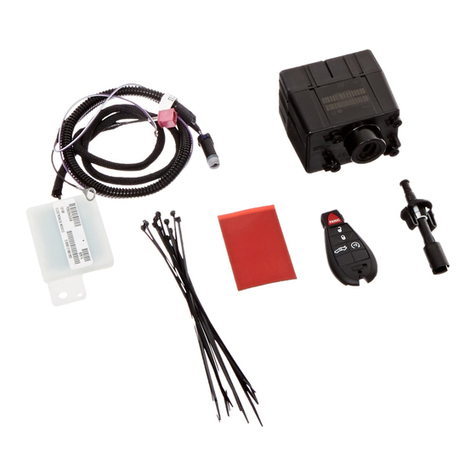
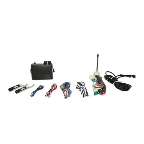
CALLOUTDESCRIPTIONQUANTITY
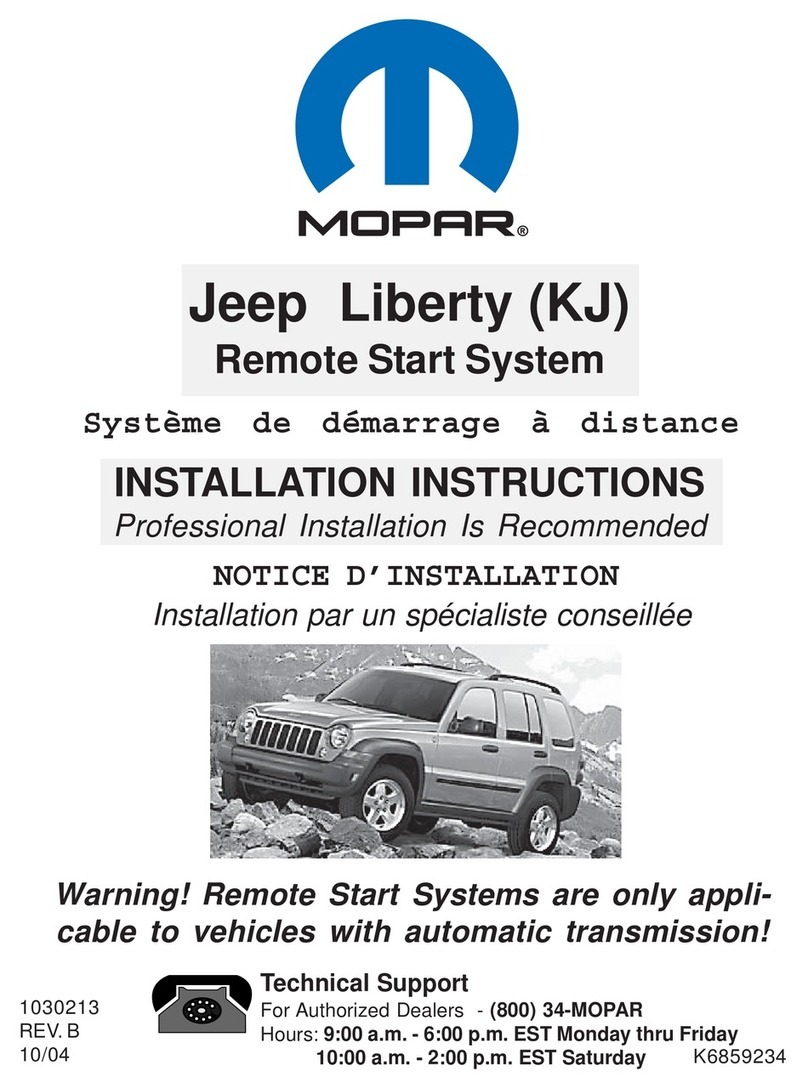
1HoodSwitchHarness1
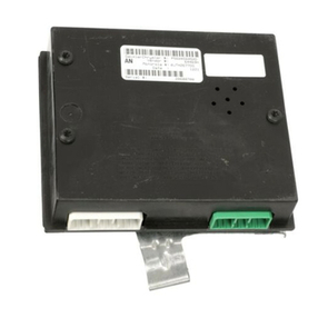
2WirelessIgnitionModule(WIN)1
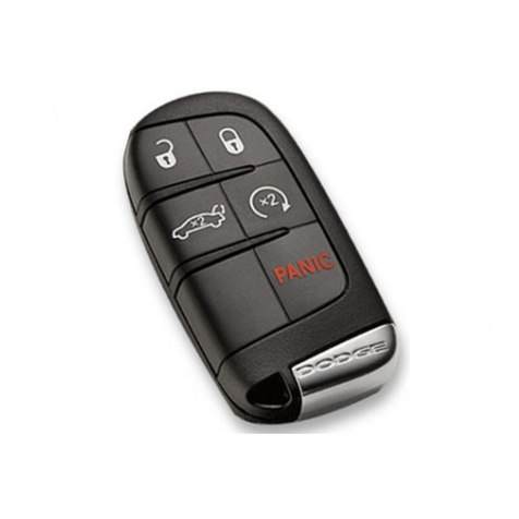
3FOBIK2
4WINAntenna1
5HoodAjarSwitch1
6ZipTies10
CAUTION:
XBMremotestartcanONLYbeinstalledonvehiclesthathavethefollowingfactoryoptions:AutomaticTrans
mission,RemoteKeylessEntryandImmobilizer.
WinFobikbasedvehicles,thesalescodemustbeaddedtothedatabaseandtheRestoreVehicleConfiguration
(usingadiagnosticscantool)mustbeperformedpriortoinstallingthenewWINmodule.Failuretodosowill
rendertheWINmodule’sremotestartfunctioninoperative.
Thetechnicianshouldwait1/2hourbetweenaddingXBMsalescodeinDealerConnectbeforeinstallingtheWIN
module&restoringvehicleconfiguration.Intheinterim,thetechniciancaninstallallothercomponentsexcept
theWINmodule.
NOTE:Priortoinstallation,obtainthefourdigitPINfromthedealership'spartsdepartment.
RESTOREVEHICLECONFIGURATION
NOTE:ThewiTECHsoftwarelevelmustbeatthelatestreleasetoperformthisprocedure.
1.VINmustbeupdatedwiththesalescodeoftheaddedaccessoryinordertoenablesystemfunctionality.Usingthe
DealerCONNECTwebsiteandthewiTECHdiagnosticapplication,completethevehicleconfiguration.
2.Logontohttps://dealerconnect.chrysler.com.
3.Inthe"VehicleOption"screenunderthe"GlobalClaimsSystem"categoryinthe"Service"tab,enterthevehicle
VIN,fourdigitpinnumberobtainedfromthedealershippartsdepartmentandaddsalescode(s)notedbelowasa
"DealerInstalledOption".
XBM(REMOTESTART)
4.ConfirmthatthenewsalescodehasbeensuccessfullyaddedtotheVIN.
5.WiththewiTECHdiagnosticapplication,performthefollowingstepsformtheInitialStartUpScreen:
•Selectthe"DIAGNOSTICPROCEDURES"tab
•Highlight"RESTOREVEHICLECONFIGURATION"
•Selectthe"RunDiagnostic"button
•Select"CONTINUE"
•VerifythatthevehicleVINnumberiscorrect
•Onceverified,selectthe"CorrectVIN"button
•NoteOnScreeninstructionsandselectthe"Close"button
PROCEDURESTEPS:
Dec01,2009K6860933
4280189

3
1.Disconnectandisolatethenegativebatterycable.
2.Openthehood.
3.Locatetheopening(1)designatedforthehoodajar
switchonthebraceneartherearpassengersideof
theenginecompartment.
4.Routethehoodswitchharness(1)underneaththe
braceandthroughtheopeningdesignatedforthe
hoodswitch.
5.Connectthehoodswitch(2)tothehoodswitchhar
ness(1).
6.Onceconnected,insertthehoodswitch(2)intothe
opening,turnthehoodswitch(2)untilproperlyseated.
7.Routethehoodswitchharness(2)intotheengine
compartment.
8.Locatethefactorygroundlug(1)onthepassenger
wheelwell/shocktower.Removethenut.
9.Installthehoodswitchgroundterminalontothefac
torygroundlugandreinstallthenut.
10.Securethehoodswitchharness(2)tothevehiclehar
nessusingthetiestrapssuppliedinthekit.
Dec01,2009K6860933
4280189

4
11.OpenthepositivebatterycablenutcoverontheTIPM
toexposenut.
12.Removethebatterycablenutandthebatterycable
fromtheTotallyIntegratedPowerModule(TIPM).
13.RemovetheTIPMcover.
14.Disengagethethreeretainingtabs(1)toremovethe
TIPMfromit'smountingbracket.
15.LifttheTIPMtogainaccesstotheconnectors..
16.LocatetheconnectorlabeldB(1).
17.DisconnecttheconnectorlabledB(1)fromtheTIPM.
Dec01,2009K6860933
4280189

5
18.Removethesecondarylockfromthefrontofthecon
nector(1).
19.Locatepincavity10(10)ontheconnector'smating
side.
20.Lookingintotheconnector'srear/wiresideview,insert
theviolet/lightbluewire(1)fromthehoodswitchhar
nessintothepin10cavity.
Dec01,2009K6860933
4280189

6
21.Installthesecondarylocktothefrontoftheconnector
(1).
22.ConnecttheconnectorlabledB(1)totheTIPM.
23.PositiontheTIPMoverthemountingbracket.
24.Engagethethreeretainingtabs(1)bypushingdown
ontheTIPM.Makesurethethreeretainingtabs(1)
snapintoplace.
25.InstallthecovertotheTIPM.
Dec01,2009K6860933
4280189

7
26.Installthebatterycablenutandthebatterycableto
theTotallyIntegratedPowerModule(TIPM).
27.ClosethepositivebatterycablenutcoverontheTIPM.
28.UsingtrimstickC4755orequivalent,removethecen
tertrim/radiobezel.
29.UsingtrimstickC4755orequivalent,removethetrim
panellocatedontheleftsidedooropening.
30.Removethescrewsecuringthelowerinstrument
panelcovertotheleftsidedooropening.
31.Removethescrewsecuringthelowerinstrument
panelcovernearthehoodlatchswitch.
32.Removethelowerinstrumentpanelcover(2)anddis
connectthetrunkreleaseswitch.
33.Removetheboltsthatsecuretheinstrumentpanel
steeringcolumncoverreinforcement(1)tothe
bracketandremovethereinforcement(1)fromthe
vehicle.
34.Usingatrimstickorequivalent,gentlypryalongthe
edgeofthetrim(1)toremovetheinstrumentcluster
trim.
Dec01,2009K6860933
4280189

8
35.Removeadhesivebackingononesideandapplythe
twosidedtape(1)tothebottomoftheremotestart
antenna(2).
36.Pressthetape(1)firmlyfor30seconds.
37.Usingafishtapeorequivalent,routetheantennahar
ness(3)downthroughtheopeningneartheaircondi
tionerducts.
38.Finishroutingtheremotestartantennaharnesstothe
dashareaneartheignitionWINmodule.
39.Removetheremainingadhesivebackingfromthetwo
sidedtapeandplacetheremotestartantennatothe
topoftheairconditioner/heatingduct.Pressfirmlyfor
30seconds.
Dec01,2009K6860933
4280189

9
40.Removethe4screwsfromtheWIN(1).
41.RemovetheWIN(1)fromtherearoftheinstrument
panelbringingitthroughtheopeningbelowthesteer
ingcolumnanddisconnecttheelectricalconnector(2)
fromtheWIN.DiscardthefactoryWINmodule(1).
42.Connecttheelectricalconnectorandremotestartan
tennaharnessconnectortotheWINsuppliedinthe
kit.
43.InstalltheWINintotheinstrumentpanel.
44.Installthefourscrews(1)securingtheWINtothein
strumentpanel.
Dec01,2009K6860933
4280189

10
45.Reinstallthecentertrim/radiobezel.
46.Reinstalltheinstrumentclustertrim.
47.Installthescrewsthatsecuretheinstrumentpanel
steeringcolumncoverreinforcement(1)tothe
bracket.Tightenthescrewssecurely.
48.Connectthetrunkreleaseswitchandinstallthelower
instrumentpanelcover(2).
49.Installandtightenthescrewsecuringthelowerinstru
mentpanelcovernearthehoodlatchswitch.
50.Installandtightenthescrewsecuringthelowerinstru
mentpanelcovertotheleftsidedooropening.
51.Installthetrimpanellocatedontheleftsidedooropen
ing.
PROGRAMMINGTHEWIN
CAUTION:Readallnotesandcautionsforprogrammingprocedures.
NOTE:HavethevehiclePINreadilyavailablebeforerunningtheroutine
CAUTION:IfthePCMandWINarereplacedatthesametime,thePCMMUSTbeprogrammedbeforetheWIN.
1.Connectabatterychargertothevehicle.
2.WiththewiTECHdiagnosticapplication,performthefollowingsteps:
•Select"WIRELESSCONTROLMODULE(WCM)"
•Selectthe"MISCELLANEOUSFUNCTIONS"tab
•Highlight"WINREPLACED"
•Selectthe"StartMiscFunction"button
•Select"NEXT"
•EnterthePINwhenprompted.
•Select"NEXT"
•VerifythatthePINnumberiscorrect
•Onceverifiedselect"NEXT"
•Select"NEXT"
•NoteOnScreeninstructionsandselectthe"FINISH"button
Dec01,2009K6860933
4280189

11
•Cycleignitionkeyafterthesuccessfulroutinecompletion.
PROGRAMMINGIGNITIONKEYSTOTHEWIN
CAUTION:Readallnotesandcautionsforprogrammingprocedures.
NOTE:HavethevehiclePINreadilyavailablebeforerunningtheroutine
1.Connectabatterychargertothevehicle.
2.WiththewiTECHdiagnosticapplication,performthefollowingsteps:
•Select"WIRELESSCONTROLMODULE(WCM)"
•Selectthe"MISCELLANEOUSFUNCTIONS"tab
•Highlight"PROGAMMINGIGNITIONKEYSORKEYFOBS"
•Select"NEXT"
•EnterthePINwhenprompted.
•Select"NEXT"
•VerifythatthePINnumberiscorrect
•Onceverifiedselect"NEXT"
•NoteOnScreeninstructionsandselectthe"FINISH"button
•Cycleignitionkeyafterthesuccessfulroutinecompletion.
NOTE:IftheoriginalkeysdonotsuccessfullyprogramtothenewWINaftertheproperproceduresarefollowed
correctly,programmingnewkeyswillbenecessary.
NOTE:AmaximumofeightkeyscanbelearnedbytheWIN.OnceakeyislearnedbyaWIN,thatkeyhasac
quiredtheSecretKeyforthatWINandcannotbetransferredtoanyothervehicle.
ECURESET
NOTE:ThewiTECHsoftwarelevelmustbeatthelatestreleasetoperformthisprocedure.
CAUTION:Readallnotesandcautionsforprogrammingprocedures.
1.Connectabatterychargertothevehicle.
2.WiththewiTECHdiagnosticapplication,performthefollowingsteps:
•Select"WIRELESSCONTROLMODULE(WCM)"
•Selectthe"MISCELLANEOUSFUNCTIONS"tab
•Highlight"RESETECU"
•NoteOnScreeninstructionsandselectthe"NEXT"button
•Select"FINISH"
WINDOWCALIBRATION
NOTE:Vehiclesequippedwiththeautoupfeaturemusthavethewindowscalibratedafterabatterydisconnect.
NOTE:Thedoormustbecompletelyclosedwhenstartingthisstep.
1.Sitinthedriverseatandclosethedoor.
2.Lowerthewindowpartofthewaydown.
3.Runthewindowtothefulluppositionandcontinuetoholdtheswitchforanadditionaltwoseconds.
4.Runthewindowtothefulldownpositionandcontinuetoholdtheswitchforanadditionaltwoseconds.
5.Raisethewindowtothefullupposition.
6.Repeatthestepsfortheremainingwindows.
UPDATEPRESSURETHRESHOLDS
NOTE:ThewiTECHsoftwarelevelmustbeatthelatestreleasetoperformthisprocedure.
NOTE:ThevehiclemustbedrivenbeforetheTPMSlightwillturnoff.
CAUTION:Readallnotesandcautionsforprogrammingprocedures.
NOTE:HavethevehiclePINreadilyavailablebeforerunningtheroutine
1.Connectabatterychargertothevehicle.
Dec01,2009K6860933
4280189

12
2.WiththewiTECHdiagnosticapplication,performthefollowingsteps:
•Selectthe"TIPMCGW"
•Selectthe"MISCELLANEOUSFUNCTIONS"tab
•Highlightandselect"UPDATEPRESSURETHRESHOLDS"
•NoteOnScreeninstructionsandselectthe"NEXT"button
•Verifycurrentsettings,selectthe"NEXT"buttontochangesettings
•Select"NEXT"
•EnterthePINwhenprompted.
•Select"NEXT"
•VerifythatthePINnumberiscorrect
•Onceverified,select"NEXT"
•Select"NEXT"
•WaitfortheWCM/WINtoupdateit'sconfiguration
•OncetheWCM/WINconfigurationiscomplete,select"NEXT"
•NoteOnScreeninstructionsandselectthe"FINISH"button
TEMPORARYREMOTESTARTDISABLE
NOTE:ThewiTECHsoftwarelevelmustbeatthelatestreleasetoperformthisprocedure.
CAUTION:Readallnotesandcautionsforprogrammingprocedures.
1.Connectabatterychargertothevehicle.
2.WiththewiTECHdiagnosticapplication,performthefollowingsteps:
•Selectthe"TIPMCGW"
•Selectthe"MISCELLANEOUSFUNCTIONS"tab
•Highlightandselect"TEMPORARYREMOTESTARTDISABLE"
•NoteOnScreeninstructionsandselectthe"NEXT"button
•Selectthe"DISABLE"buttontoactivatetheremotestartfunction
•Select"YES"toresetthemoduleandexittheroutine,select"NO"totogglethevalueback
•Select"FINISH"
CLEARALLDTC'S
NOTE:ThewiTECHdiagnosticapplicationisthepreferredmethodforclearingallDTC's.
NOTE:ThewiTECHsoftwarelevelmustbeatthelatestreleasetoperformthisprocedure.
ACTIVATETHEREMOTESTART
Toactivatetheremotestartthevehiclemusthavebeendrivenatleast35MPH.
Withthevehicleoff,andthedoorsclosedandlocked,verifytheremotestartisfunctioningproperly.
Dec01,2009K6860933
4280189

1
DÉMARRAGE À DISTANCE
CHRYSLER 300C / DODGE CHARGER
Dec. 1, 2009 K6860933
4280189

2
LÉGENDE DESCRIPTION QUANTITÉ
1 Faisceau du commutateur de capot 1
2Noeud d'allumage sans fil(WIN) 1
3FOBIK 2
4Noeud d'allumage sans fil - antenne 1
5Contacteur de capot entrouvert 1
6 Attaches mono-usage 10
ATTENTION:
Le démarrage à distance XBM peut être installé SEULEMENT sur les véhicules qui sont dotés des options sui-
vantes installées en usine : boîte automatique, télédéverrouillage et antidémarreur.
Pour les véhicules dotés d'une clé Fobik et du WIN, le code de ventes doit être ajouté à la base de données et
la fonction Restaurer la configuration du véhicule (à l'aide de l'analyseur) doit être effectuée avant d'installer le
nouveau module WIN. Le défaut de suivre cette consigne entraînera le non-fonctionnement de la fonction de
démarrage à distance du module WIN.
Le technicien devrait attendre 1/2 heure avant d'ajouter le code commercial XBM dans DealerConnect avant de
poser le module WIN et de restaurer la configuration du véhicule. Pendant ce temps, le technicien peut poser
tous les autres composants sauf le module WIN.
REMARQUE: Avant la pose, se procurer le NIP à quatre chiffres du service des pièces du concessionnaire.
RESTAURER LA CONFIGURATION DU VÉHICULE
REMARQUE: La version du logiciel wiTECH doit être à la plus récente version pour effectuer cet essai.
1. Le NIV doit être mis à jour avec le code de vente de l'accessoire ajouté, afin de permettre la fonctionnalité du sys-
tème.À l'aide du site Web DealerCONNECT et de l'application de diagnostic wiTECH, compléter la configuration du
véhicule.
2. Connecter à https://dealerconnect.chrysler.com.
3. Dans l'écran «Vehicle Option» (option de véhicule) sous la catégorie «Global Claims System» (système de récla-
mations global) dans l'onglet «Service», entrer le NIV, numéro d'identification à quatre chiffres obtenu du service
des pièces du concessionnaire et ajouter le(s) code(s) de vente noté(s) ci-dessous en tant que «Dealer Installed
Option» (option installée en concession).
XBM (DÉMARRAGE À DISTANCE)
4. Confirmer que le nouveau code de vente a été ajouté au NIV (numéro d'identification du véhicule) avec succès.
5. À l'aide de l'application diagnostic wiTECH, effectuer les étapes suivantes à partir de l'écran Initial Start Up (démar-
rage initial) :
• Sélectionner l'onglet «DIAGNOSTICS PROCEDURES» (procédures de diagnostic).
• Mettre en surbrillance «RESTORE VEHICLE CONFIGURATION» (récupérer la configuratin du véhicule).
• Sélectionner le bouton «Run Diagnostic (procéder au diagnostic).
• Sélectionner «CONTINUE« (continuer).
• S'assurer que le NIV est exact et correct.
• Une fois la vérification terminée, sélectionner le bouton «Correct VIN» (NIV correct).
• Noter les instructions à l'écran instructions et sélectionner le bouton «CLOSE» (fermer).
Dec. 1, 2009 K6860933
4280189

3
ÉTAPES DE PROCÉDURE :
1. Déconnecter et isoler le câble négatif de la batterie.
2. Ouvrir le capot.
3. Placer l'ouverture (1) désignée au contacteur de capot
entrouvert sur l'entretoise, près de l'arrière du côté
passager du compartiment moteur.
4. Faire passer le faisceau du contacteur de capot (1) sous
la bride et à travers l'ouverture du commutateur de capot
désigné.
5. Brancher le commutateur de capot (2) sur le capot du fais-
ceau (1).
6. Une fois raccordé, insérer le commutateur de capot (2)
dans l'ouverture, tourner le commutateur de capot (2) jus-
qu'à ce qu'il soit bien en position.
7. Faire passer le faisceau du commutateur (2) dans le com-
partiment moteur.
8. Localiser l'attache de masse d'origine (1) de la roue/tou-
relle d'amortisseur du côté passager.Déposer l'écrou.
9. Poser la borne de masse de commutateur du capot sur
l'attache de masse d'origine reposer l'écrou.
10. Fixer le faisceau de câblage du contacteur du capot (2)
dans le faisceau du véhicule à l'aide des serre-câbles four-
nis dans la trousse.
Dec. 1, 2009 K6860933
4280189

4
11. Ouvrir le capuchon d'écrou de câble positif de batterie sur
le module d'alimentation totalement intégré (TIPM) pour
exposer l'écrou.
12. Déposer l'écrou du câble de la batterie et le câble de la bat-
terie du module d'alimentation totalement intégré (TIPM).
13. Déposer le couvercle du module d'alimentation totalement
intégré (TIPM).
14. Dégager les trois pattes de retenue (1) pour retirer le TIPM
de son support de montage.
15. Soulever le module d'alimentation totalement intégré
(TIPM) pour accéder aux connecteurs.
16. Repérer le connecteur marqué B (1).
17. Débrancher le connecteur marqué B (1) du module d'ali-
mentation totalement intégré.
Dec. 1, 2009 K6860933
4280189

5
18. Déposer la serrure secondaire de l'avant du connecteur
(1).
19. Localiser la cavité 10 broches (10) sur le côté du connec-
teur correspondant.
20. En regardant dans l'arrière du connecteur de filenvue
latérale, insérer le fil violet/bleu clair (1) du faisceau du
contacteur de capot dans la cavité 10 broches.
Dec. 1, 2009 K6860933
4280189

6
21. Poser la serrure secondaire à l'avant du connecteur (1).
22. Brancher le connecteur marqué B (1) au module d'alimen-
tation totalement intégré (TIPM).
23. Placer le TIPM sur le support de montage.
24. Engager les trois pattes de retenue (1) en poussant vers le
bas sur le TIPM.S'assurer que les trois pattes de retenue
(1) s'enclenchent en place.
25. Poser le couvercle sur le TIPM.
Dec. 1, 2009 K6860933
4280189

7
26. Poser l'écrou du câble de batterie et le câble de batterie
au module d'alimentation totalement intégré (TIPM).
27. Fermer le capuchon d'écrou de câble positif de batterie
sur le TIPM.
28. À l'aide de la baguette de garnissage C-4755 ou d'un
outil équivalent, déposer le garnissage central de
l'encadrement de la radio.
29.Àl'aided'unebaguettedegarnissageC-4755oud'un
outil équivalent, déposer le panneau de garnissage du
côté gauche situé sur l'ouverture de la porte.
30. Déposer les vis fixant le couvercle inférieur du tableau de
bord au côté gauche de l'ouverture.
31. Déposer les vis fixant le couvercle inférieur du tableau de
bord, près du loquet du capot.
32. Déposer le couvercle inférieur du tableau de bord (2) et
débrancher le commutateur d'ouverture du coffre.
33. Déposer les boulons qui fixent le renfort de couvercle de
colonne de direction du tableau de bord (1) sur le support
et déposer le renfort (1) du véhicule.
34. À l'aide d'une baguette de garnissage ou d'un outil équi-
valent, soulever délicatement le long du bord du garnis-
sage (1) pour déposer le bloc d'instruments.
Dec. 1, 2009 K6860933
4280189

8
35. Retirer l'endos adhésif sur un côté et appliquer du ruban
double face (1) à la base de l'antenne du démarreur à dis-
tance (2).
36. Presser le ruban adhésif (1) fermement pendant 30
secondes.
37. À l'aide d'un ruban de tirage ou un équivalent, faire passer
le faisceau de l'antenne (3) vers le bas à travers l'ouver-
ture près des conduits du climatiseur.
38. Terminer l'acheminement du faisceau de l'antenne de
démarrage à distance dans l'aire du tableau de bord près
du module d'lumage WIN.
39. Déposer l'endos adhésif qui reste du ruban double face
et placer l'antenne de démarrage à distance et le sommet
du conduit de climatisation/chauffage.Appuyer fermement
pendant 30 secondes.
Dec. 1, 2009 K6860933
4280189
Table of contents
Languages:
Other Mopar Remote Starter manuals

Mopar
Mopar 82212517 User manual

Mopar
Mopar 82215277AB User manual

Mopar
Mopar Remote Start System User manual

Mopar
Mopar 82209870AG User manual

Mopar
Mopar 82213587 User manual

Mopar
Mopar XBM User manual

Mopar
Mopar 82212895 User manual

Mopar
Mopar EVS II User manual

Mopar
Mopar 82210888xx User manual
Mopar
Mopar 82209982AH User manual

Mopar
Mopar Jeep Commander 82211019xx User manual

Mopar
Mopar K6861211 User manual

Mopar
Mopar 82212423AB User manual

Mopar
Mopar 82212610AB User manual

Mopar
Mopar DR User manual

Mopar
Mopar 82208859 User manual

Mopar
Mopar 82211023 Series User manual
Mopar
Mopar 82211019xx Jeep Commander (XK) 2008 User manual

Mopar
Mopar 82208861 User manual

Mopar
Mopar 82215575AB User manual