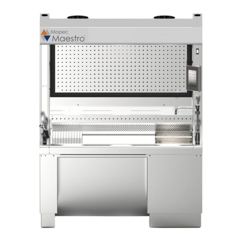
Mopec MB800 User manual

USER MANUAL
www.mopec.com
MB800
Grossing Station
Rev 10-7-16 ©

P a g e | 2

P a g e | 3
TABLE OF CONTENTS
UNPACKAGING YOUR PRODUCT ..………………………………………………4
INSTALLATION ………..……………………………………………………………..5
ROUGH IN DRAWING ……………………………………..………………..7
INTRODUCTION ……………………………………………………………………...9
MB800 DRAWING …………………..…………………………………….....10
FEATURES ………………….………………………………………………………....11
TOUCH SCREEN OPERATION
Overview ………………………………………………………………………12
Main Screen …………………………………………………………………..13
Ventilation ……….……………………………………………………….…...18
Filter Hour Meter ………………………………………………………….....19
Alarm Configuration …………………………………………………….…..20
Energy Saving Mode ……………………………………………………..….21
Mopec Screen ………………………………………………………….….….22
Feature Configuration ……………………………………………….……...23
Calibration …………………………………………………………….………23
Product Information Screen ……………………………………….………24
System Security ………………………………………………………..…....25
Touch Free System …………………………………………………..……...26
Touch Screen Usage ………………………………………………..…….…27
Troubleshooting Controls …………………………………………..……...27
Component Testing and Diagnosis ………………………………..….….29
Operating Logic ………………………………………………………..……..31
OPTION INFORMATION ………………………..………..………………..………....46
AIR HANDLING ……………………………………………………………….……….59
CLEANING AND MAINTENANCE
Disinfecting and Cleaning ………………………………..………………..61
Clear Disposal Jam ..………………………………………………..……....64
Lift Reset Procedure ………………………………………………..……....65
Filter information and evaluation …………………………………...…….66
Parts ………………………………………………………………………...….67
Preventive Maintenance
Touch Controller ……………………………………………...……..68
Unit ……………………………………………………………………..69
Calibration Log ……………………………………………………….71
Filter Change Log …………………………………………………….72
Maintenance Log ……………………………………………………..73
WARRANTY………………………………………………………………………..…….74
SAFETY LABELS ………………………………………………………..……..………75
TROUBLE SHOOTING ……………………………………………………………..…..76
ELECTRICAL DIAGRAMS ………………………………………………………..…...77
CERTIFICATES ..…………………………………………………………………..……82

P a g e | 4
UNPACKING
1) Carefully inspect the exterior of the shipping container before opening. If the crate is damaged and
the product has sustained damage then immediately contact Mopec and the freight carrier. Never
discard the shipping container even if it is damaged beyond recognition.
2) Have the delivery driver note any suspected damage on the Bill of Lading and sign it. Mopec will help
assist in filing a claim for product repair and/or replacement.
3) Carefully open the containers and inspect the equipment for concealed damage. If visible damage is
noticed (i.e. broken welds, dented stainless, scratches, etc.) follow through as noted above. Do not
discard the shipping material. They are important in settling claims.
CAUTION: There are loose components in the packaging of your product. Be very careful in examining
the packaging material as it may contain installation parts and/or product components.
INSPECTION
1) After carefully unpacking your Mopec Grossing station please inspect the items in the list below prior
to installing the unit. The Grossing station should be thoroughly checked for loose screws, defects, or
damage that may have occurred during shipping or packaging.

P a g e | 5
INSTALLATION
MB800 Grossing Station Installation Instructions
Locate package of smaller items (dissection board, tissue boxes, duct hose or filters)
When removing from the shipping platform, be careful if the unit has a foot pedal. The unit should be removed from
the shipping platform as to not cause damage to the copper plumbing attached to the foot pedal
Leveling and Setting Unit in Place
The unit should be off the floor and resting on the leveling pads. The unit should be leveled to ensure proper drainage.
This allows water to evaporate or dry in case of a leak without getting trapped by the base of the unit Ensure there is a
Minimum of 6.5” from the wall to the back of the unit. This allows for elevating units to move freely without any
obstructions to the wall.
Utility Connections
The only connections necessary are the Electric, Cold and Hot water supply, the drain connection and the HVAC
connections if in house ventilation. If the disposal option is ordered the disposal will need to be installed prior to the
electrical hook up. The unit is already pre wired and plumbed for the options ordered.
Electrical Connection
All electrical, water and ventilation stubs should be prepared in accordance with our rough-in dimensions shown on
rough in diagram of this manual.
The electrical service provided for the MB600 must include:
1) A switch or circuit breaker for each circuit to which the wiring harnesses from the workstation will be
connected.
Remove the access panels (see photo on next page). Elevate the unit to its maximum upper position using the Vertical
Position Switch. If ordered, install the optional disposal and make all connections that apply, including the additional
115V, Single Phase, 60 Hz, 20 Amp circuit to your electrical service. (This should be on a separate dedicated line.)
Replace the access panels.
Each MB Series Grossing Station has a three foot whip for attachment to the facility, unless a plug and cord are
requested. The whip leads are labeled. And depending on the options selected there are either 3 wires or 5 wires. L1
and C1 are for the unit electrical options such as lights, lifts and fans if a recirculation unit. L2 and C2 are for the
disposal.
115V Info
Without a disposal there are three wires:
Black Labeled as L1
White Labeled as C1
Green w Yellow Stripe Ground
With the Disposal there are five wires
Black Labeled as L1
White Labeled as C1
Green w Yellow Stripe Ground
Red Labeled L2
White Labeled C2
The flexible water tight conduit and connections is the preferred conduit and is not provided with the unit. This is due
to an unknown length needed and variances possible in the rough in process. If the disposal option is purchased there
MUST be two separate circuits for the two circuits on the grossing station. You must have separate circuits for the
disposal and unit.

P a g e | 6
Drain Connection
The MB Grossing stations are equipped with 1.5” Diameter drain and connections. DO NOT modify the drain line or
connections without contacting MOPEC first. The Units are built in accordance with the rough in drawings specific to
the unit. The drain connection provided unless specifically requested otherwise is Orion Acid Waste Pipe 1.5”
Diameter. The height is per the rough in drawings provided at the time of the order.
Water Supply Connection
The water supply connections are ½” DIA copper pipe. The unit has been cleared of water and debris during the
manufacturing and testing of the unit. The rough in drawing for the unit suggests a 1/4 turn valve to be connected to
the wall. This is to allow the water to be localized and disconnected should the need arise to work on plumbing in the
future. Before connecting the unit to the facility water supply, check the lines in the facility for debris by flushing the
lines for a moment. After the connections are made remove the aerator from the faucet and turn the water on and
open the faucet and other water options after the faucet to allow any debris to evacuate the system. Then one option
at a time, open the valves for the other water options (i.e. Perimeter Rinse, Spray Hose and then the Disposal). This is
the time to look for leaks or other plumbing issues. The plumbing is tested for leaks and function at the facility and is
put under pressure for 45 minutes to check for leaks. However the plumbing is hard copper and soldier connections.
During transport a unit may experience a failed soldier joint. Contact MOPEC immediately if there is a leak.
Ventilation Connection
Ventilation is one of two types for the MB Grossing stations; In House Ventilation or Recirculation. For in house the
unit is connected to the facility ventilation system via duct work. The duct work will vary depending on the model of
grossing station.
In House
If your unit elevates, it will have two 8” diameter flexible duct hoses. The duct hoses are connected to the grossing
station chamber door on top of the unit and to corresponding stubs at the ceiling per the rough in drawing. The ducts
are provided as well as the stainless steel band clamps. The typical flexible duct hose length is 3 foot. If your unit does
not elevate the ventilation connection is on the top back of the unit and will vary by model.
MB100/MB200 (48” wide models) the connection is a 3” x 46” rectangular stub on the top back of your unit. The duct
work is not provided by Mopec unless specifically ordered.
MB400 (60” wide models) the connection is a 3” x 58” rectangular stub on the top back of your unit. The duct work is
not provided by Mopec unless specifically ordered.
MB600/MB650, MB670 and MB700 the connection is an 8” round duct supplied with the unit. MB600. MB650 and
MB700 have two ducts the larger MB670 has three 8” round ducts. Clear PVC flexible duct is provided with the unit as
well as mounting clamps.
Recirculation
For recirculation models, the filters will need to be installed and the clearance above the unit verified at its highest
elevation if the unit elevates. You should have a minimum of 12 inches or more above the grossing station at its
highest position. Air flow is generated by multiple fans in the recirculation models. They are set up so one fan is on
constantly when the unit is on and the other fan is controlled by a rheostat to control volume/speed.
** Caution ** These are general guidelines and installation is specific for each of the MB units.
Professional installation is recommended.

P a g e | 7
Rough In Drawings
REFERNCE ONLY for specifics refer to your approval drawing
The electrical service provided for the MB600 must include:
1.) A switch or circuit breakers to which the wiring harnesses
from the workstation will be connected.

P a g e | 8
MB800

P a g e | 9
INTRODUCTION
Mopec’s MB800 grossing station is available with a variety of options which make them advantageous for a
wide variety of users.
The MB800 workstation provides a safe work area free from toxic formaldehyde fumes. The MB800 may be
ducted to an existing laboratory exhaust system or the option of “Filtration/Re-circulation” system requires no
ducting and incorporates variable speed exhaust fans that evacuate the work surface of harmful
formaldehyde fumes. Toxic formaldehyde fumes from the work area are filtered through potassium
permanganate impregnated filters which safely absorb and neutralize those fumes. The disposable filters are
easily accessible through a specially designed front filter access panel.
The MB800 incorporates an advanced adjustable height technology into an all stainless steel workstation.
From its lowest counter height of 29 ½” to a maximum counter height of 41 ½”. With the capability to preset 3
elevating positions in memory.
With the Industrial Touch Screen Controller the unit can be set, adjusted and functions such as fan speed, air
flow, optional formalin dispensing and collection, all monitored from a central touch screen.
Manual or hands free control of lights, fans for a more ergonomic environment and single lever mixing valve
faucet. Recessed 7” LED Lights. GFCI with 5 Amp USB Ports, and additional USB ports and camera ready
integration. With functions like air speed, programmable lights, motion sensor to shut the MB800 off or on
automatically when walking up to the unit.
The MB800 also features a modular back splash design to allow the user to move items they use to where
they would like them or add additional items from the tissue boxes to the paper towel dispenser, magnetic
tool bar and shelves.
Grid plates and optional work surface grid plates provide a level stable work surface while allowing fluids to
be flushed or drain from the work surface
.

P a g e | 10
UNIT DRAWING
MB800

P a g e | 11
FEATURES
The “MB800”consists of the following:
Work Grid: 14 Gauge, type 304 Stainless Steel with a # 4 Satin Finish
Housing: 18 & 20 Gauge, Type 304 Stainless Steel with a # 4 Satin Finish
Electrical: 115 v / 1ph / 60 Hz Current Draw: 20 Amp maximum
Electrical: 230 v / 1ph / 50 Hz Current Draw: 10 Amp maximum
Standard Features
Adjustable Magnetic Instrument Tool Bar
Adjustable Paper towel Holder
Adjustable Stainless Steel Shelves
Adjustable Storage Shelf
Backdraft Ventilation
Built In USB Data Ports
Dissection Board Grid Plate
Elevating Workstation w/3 memory positions
G.F.C.I. Outlet with USB 5V plugs
Hand Spray Rinse
Large Rinse Sink
Modular Backsplash
Perforated Vent Grill
Recessed LED Lighting
Single Lever Hot/Cold Water Fixture
Stainless Steel Paper Towel Holder
Washable In/Cm Ruler
Work Surface Grid Plates
Optional Features
1 HP Waste Disposal
Additional Adjustable Backsplash items
Built in Camera –Multiple Available Options
Computer Monitor/Keyboard Ultra
CPU Mounting Bracket
Dictation Equipment Stand
Dissection Board Grid Plate
Elevated Grid Plate (1” taller in Height)
Foot Pedal
Formalin Collection System
Formalin Dispensing Container 2.5 Gal
Formalin Dispensing Cubetainer Style
Perimeter Rinse
Safety Splash Shield
Self-Contained Exhaust System
Ventilated Trash Container
Video Camera Arm

P a g e | 12
TOUCHSCREEN OPERATION
The GS1 is a microprocessor based system designed to enhance the functionality and user experience of a
grossing station. The GS1 system also adds new features to improve the grossing station performance while
providing a safe work environment.
The GS1 is a control system designed specifically for grossing stations to consolidate different features and
options into one system. The GS1 is a feature-rich system that includes touch-free lighting and ventilation
activation, filter usage tracking and maintenance alert, ventilation flowrate (CFM) monitoring with low
performance warning, energy saving mode, Formalin level monitoring with warning alarm, waste level
monitoring with warning alarm, touch-free water dispensing, and remote diagnostics. The GS1 system comes
with industrial grade sensors and a color touchscreen for improved reliability and user interface.
The GSC uses a color touchscreen to allow the user to scroll through multiple screens to access
configuration parameters and monitor the grossing station performance. This document includes step by step
explanations on how to configure and use the GS1 system.
The GS1 at a glance
The GS1 has multiple screens that can be viewed by pressing the upper left and right arrows. Each screen
displays information about the system. Some screens, when accessed with the proper password, allow
parameter changes and system calibration.

P a g e | 13
Main screen
When the GS1 is first powered up, the main screen, shown above, is displayed. This main screen is divided
into two sections: The upper section containing small icons and the lower section containing larger icons.
Main screen upper icons
The main screen upper section contain small icons. These icons also referred to as actuator icons. When the
user activates a device, the corresponding actuator icon will acknowledge the request and change its image
to display the device status. The purpose of these icons is to provide user feedback and to display the status
of the different devices in the grossing station. These icons do not set any alarms and do not react to user
touch.
Actuator icons indicate the status of their corresponding device by their appearance. Most icons can take on
up to 4 different appearances: the first would be to indicate that the device or feature is OFF, the second that
the device is ON, the third that the system is not equipped with the feature or that the feature is disabled, and
finally the fourth would be to indicate that the device is transitioning from one state to another (meaning from
ON to OFF or OFF to ON).
The table below gives an overview of the different icon appearances based on device status.

P a g e | 14

P a g e | 15

P a g e | 16
Main screen lower icons
The lower section of the main screen contains larger icons. These are indicator icons displaying the status of
the formalin level, the waste container level, the filter usage, and the ventilation status.
These icons can display multiple images describing the related system state. The table below gives an
overview of the different icon appearances based on system status.

P a g e | 17

P a g e | 18
Ventilation screen
The purpose of the flowrate (CFM) meter is to approximate the air flow rate. This meter is not a substitute for
an anemometer instrument. The ventilation air flow rate meter screen can be displayed by scrolling to the
right once. This screen shows the CFM meter and a few ventilation parameters.
The gauge provides a visual indicator for the CFM. The Min CFM parameter and the “Delay” parameter can
both be modified to customize the meter and its alarm triggers.
MIN (CFM): This parameter sets the minimum CFM value that is allowed before an alarm is triggered. Unlock
the system in the security screen to edit this parameter.
Delay (sec): This parameter sets the delay before setting the alarm. Unlock the system in the security screen
to edit this parameter.
Turbulence: This is a unit-less indicator to quantify how much flow fluctuations are present.
Note: All parameters that can be edited are highlighted in green. See security screen to unlock / lock the
system.

P a g e | 19
Filter hour-meter
The filter hour-meter tracks the filter run time. This is the time the ventilation CFM level is above the CFM
trigger point. Scroll to the filter usage screen to view and configure this feature
Current usage: This parameter shows the current filter usage in hours. Once this value exceeds the
maximum usage time, the alarm will sound if equipped and the filter icon will change state to Not OK.
Max usage: This parameter holds the maximum number of hours a filter can operate before replacement.
This value must be adjusted by the user based on the work environment air quality data. Below are the
default factory values for this parameter based on CFM. System security must be unlocked to edit this
parameter.
Trigger point: This parameter holds the minimum CFM level before the filter timer starts to count. This is
used to stop the timer if the ventilation is turned OFF. Unlock the system and touch the parameter to edit.
Reset timer button: When pressed, this button will reset the current filter usage hours to zero. This button is
only active when the system is unlocked.
Note: All parameter that can be edited are highlighted in green. See security screen to unlock / lock the
system.

P a g e | 20
Alarm configuration
The alarm screen can be reached by scrolling through the screens using the left or right arrows.
The alarms for the different features can be enabled / disabled by pressing on the related buttons. The
system does not have to be locked to change this configuration. A regular user can change how the alarms
are configured. A green check mark will be displayed next to the features that are configured to alarm. The
screen above shows an example where the waste level monitor has been set to alarm.
Security unlock is not needed for this configuration.
Note: When the alarm is triggered, touching the screen will mute the alarm. It is important to address the
alarm triggers and resolve the issues. The alarm will automatically turn OFF is the issue is resolved.
Table of contents
Other Mopec Laboratory Equipment manuals