Morgan MDH-930STOC User manual

USER MANUAL
Desig er
Hood
MDH-930STOC
E-mail: electrical.appliance@dksh.com
www.morgan.my
Market Expansion
Services by
www.dksh.com.my
facebook.com/morganappliances
MDH-930STOC(IM)281216.qxp_Lay ut 1 12/29/16 5:10 PM Page 1
32
C O N T E N T S
4
5
6-8
9
10
11
PARTS IDENTIFICATION AND SPECIFICATION
SAFETY PRECAUTIONS
INSTALLATION
OPERATING INSTRUCTIONS
CLEANING AND MAINTENENCE
TROUBLESHOOTING
MDH-930STOC(IM)281216.qxp_Lay ut 1 12/29/16 5:10 PM Page 2
4 5
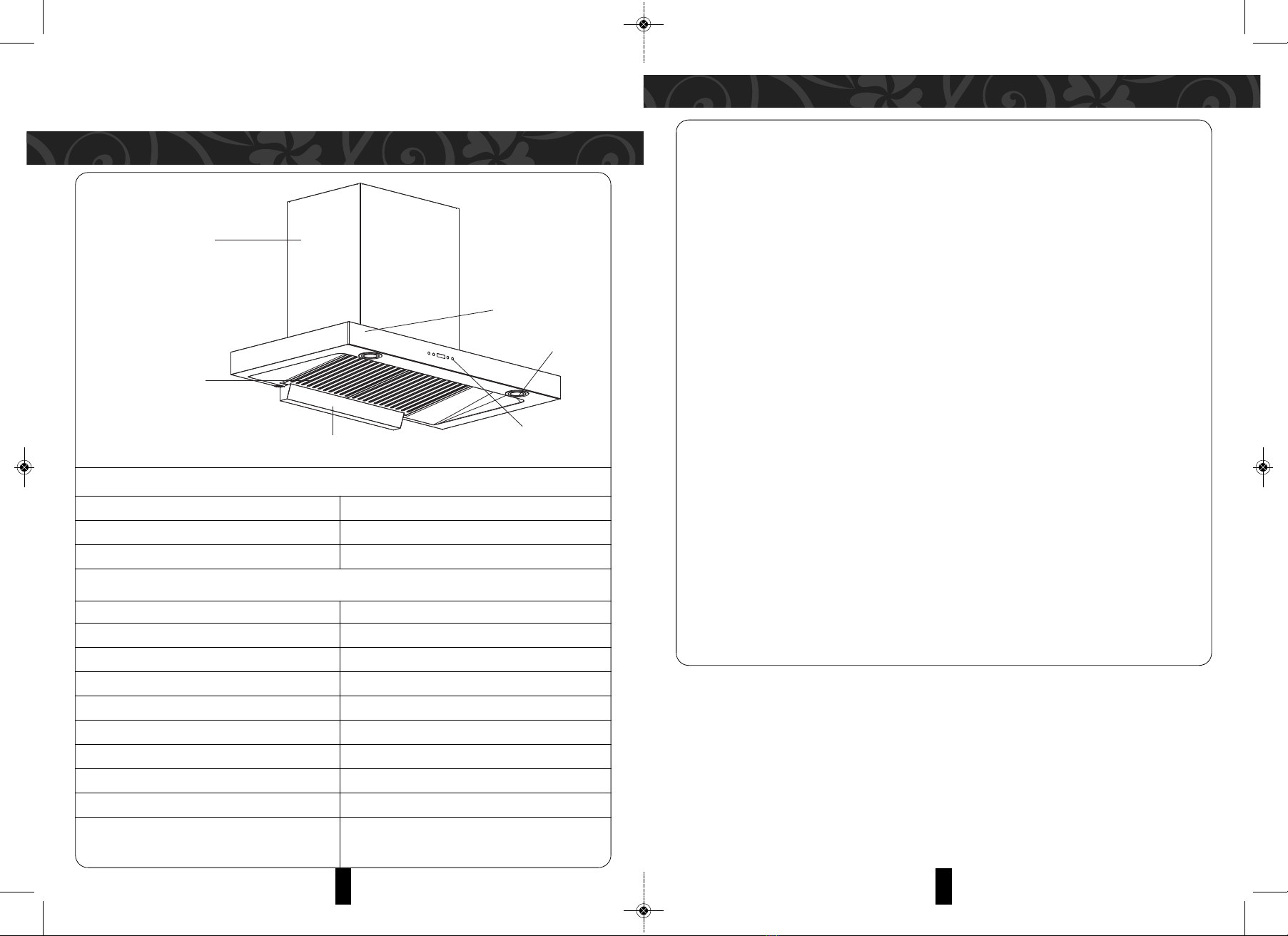
PARTS IDENTIFICATION AND SPECIFICATION
SAFETY PRECAUTIONS
Before starting the installation, consideration should be given to the difficulties to be found during
installation. Installation ust be undertaken by a qualified and co petent person confor ing to the rules
concerning the evacuation of conta inated air. The anufacturer disclai s all liability for any da age or
injury caused because of not following the instructions for installation contained in the following text.
1. Always ensure that the appliance is disconnected from the power supply and allow it to cool down completely before
cleaning and do not unplug the appliance with wet hands.
2. Before connecting to the power supply ensure that the power voltage corresponds with the voltage on the rating
plate inside the hood.
3. Ensure that the installation of any earthing cable is not connected to water pipes, lightning rod or telephone lines to
avoid electric shock.
4. Ensure that the wall must have sufficient strength to support the weight of the appliance.
5. Ensure that the appliance is horizontally.
6. Distance between exhaust holes on the wall shall be less than 1.5m. Do not install the exhaust pipe too high to avoid
oil flowing backwards.
7. Ensure that the room is has adequate ventilation when operating the appliance.
8. The air exhaust from this appliance should not be channeled to the flue of burning gas or other fuels.
9. If the power cord is damaged, it should be inspected and repaired by a suitably qualified technician or returned to
the manufacturer for further action.
10. Always turn off the power supply when replacing lamps. New lamps must be the same specification as the current
ones.
11. It is dangerous to alter the specifications or to modify this appliance in any way. Do not tamper with it or attempt to
alter it in the attempt to customize it further.
12. This appliance is not intended for use by persons (including children) with reduced physical sensory or mental
capabilities, or lack experience and knowledge, unless they have given supervision or instruction concerning the use
of the appliance by a person responsible for their safety.
13. Children should be supervised to ensure that they do not play with the appliance and its parts and accessories.
14. Educate children about the danger and safety rules associated with operating electrical appliance.
15. Do not operate any appliance with a damaged cord or plug, or after the appliance malfunctions or has been damaged
in any manner. Repairs and services should only be carried out by suitably qualified technicians or by the authorized
service center.
1
2
3
4
5
6
Thank you for purchasing a quality MORGAN appliance. We trust that you will have a pleasant experience
with your new product. To guarantee safety and best efficiency, please read this anual carefully and keep
a copy for future reference.
DIMEN ION
WIDTH (CANOPY) 895mm
HEIGHT (WITH CHIMNEY) 510+485mm
DEPTH (CANOPY) 500mm
PECIFICATION
MODEL MDH-930 TOC
MATERIAL tainless teel + Tempered Glass
VOLTAGE / FREQUENCY 220-240V~ 50/60Hz
TRAN MI ION TYLE ingle Motor
LED LIGHTING POWER (LAMP) 2 x 1.5W
CONTROL 3 peed Touch witch
FILTER Baffle Filter
MOTOR PEED 3 peed
MOTOR POWER 280W
EXTRACTION CAPACITY 1500m³/hr
1. Hood
2. Glass Panel
3. Lamp
4. Filter
5. Control Panel
6. il Cap
MDH-930STOC(IM)281216.qxp_Lay ut 1 12/29/16 5:10 PM Page 3

6 7
INSTALLATION INSTALLATION
4. PRODUCT INSTALLATION (SINGLE HOOD)
• Align the appliance to the hanger holes and secure the appliance on the wall.
• Connect the one end of exhaust pipe diameter 153mm to exhaust hole of appliance and the other end connect to the
exhaust outlet.
Note: Ensure that the range hood is hanging vertically and horizontally. Do not tilt it.
5. PRODUCT INSTALLATION (DOUBLE HOOD)
• Loosen screws and align the appliance to the hanger holes and secure the appliance on the wall.
• Align the upper hood to the proper position.
• Mark the position of the upper hood screw holes at upper side on the wall. Put the upper hood back.
• Mark the position of the upper hanger side holes. Mark the position of two middle holes of upper hanger.
• Drill marking holes, insert plastic expansion bolts, fix upper hanger, install exhaust pipe on exhaust outlet, secure
appliance, connect the exhaust pipe to air outlet of the kitchen, pull the upper hood upwards and secure the side
holes with screws.
1. INSTALLATION
• D N T earth the appliance to any water pipes, lightning rod or telephone lines or come into contact with steel and
wires to avoid the risk of electric shock.
• This appliance must be properly earthed to avoid electric shocks in the event of electricity leakage.
• Ensure that the power supply system in your home (current, voltage, connecting wires) meets the requirements of the
appliance’s power supply load.
• D N T use high capacity fuse in electrical circuit. Always select the correct ones as specified on the rating label.
2. PRECAUTIONS BEFORE
INSTALLATION
• WALL: Ensure the wall that the
appliance is to be mounted must be
hard enough to bear the weight of
the appliance.
• HEIGHT OF MOUNTING: The
recommended mounting height
should preferably be 650-750mm
above the cooking stove but is
subject to the construction of the
user’s kitchen dimensions.
3. INSTALLATION HANGER
• Measure the installation height by marking the position of the hanger on the wall. Drill holes for fixing hanger and
insert plastic expansion bolts into the holes to enhance the hanger.
MDH-930STOC(IM)281216.qxp_Lay ut 1 12/29/16 5:10 PM Page 4
98
INSTALLATION OPERATING INSTRUCTIONS
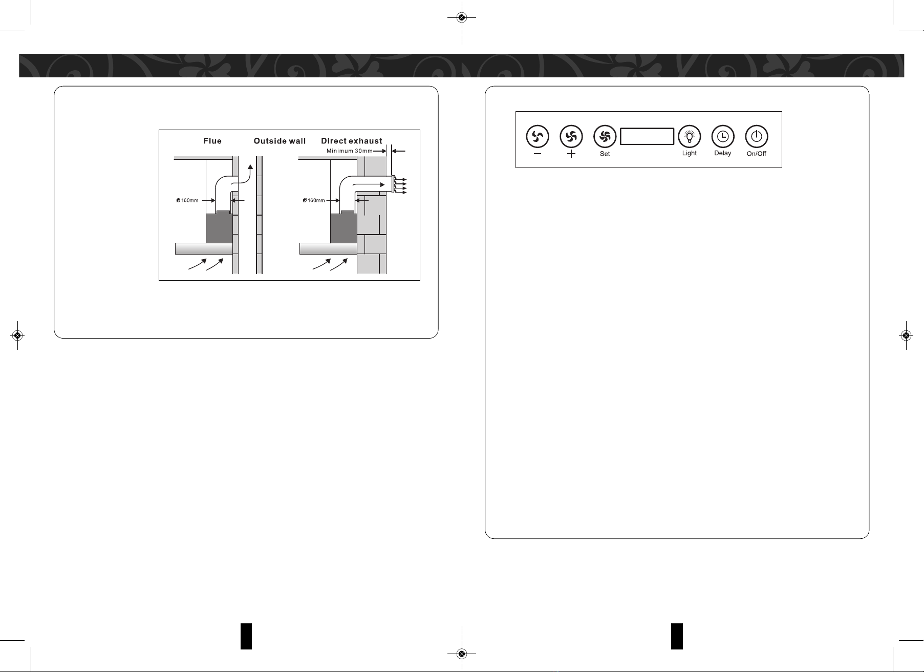
FUNCTION ILLUSTRATION
1. TO SET THE CLOCK:
• When the appliance is connected to the power supply, the display will show 12:00.
• Touch the “DELAY” button and hold for 3 seconds.
• The “12” on the hour side will start flashing. Touch “+” or “–“ button to set hour.
• Then touch the “DELAY” button again and “00” on the minute side will start flashing.
• Touch “+” or “–“ to set the minute.
• Touch the “DELAY” button to finalize timer setting.
NOTE: The ti er setting will need to be reset again in the event of a power interruption.
2. OPERATING THE APPLIANCE:
• Touch the “ N/ FF” button. The appliance will enter standby mode.
• The blower has three speeds - “SL W”, “MEDIUM” and “HIGH”. These three speeds can be toggled in-between
each other.
• Touch the “+” button to start operating at slow speed.
• Touch the “-“ button to switch to medium speed.
• Touch the “SET” button to switch to high speed.
NOTE:
– You can toggle between the speeds by touching the respective buttons.
– To switch off the appliance, touch the “ N/ FF” button, the blower will power off immediately. Touch the “DELAY”
button, the fan will continue to operate for 5 minutes and the appliance will then switch off.
3. OPERATING THE LIGHTS:
• The lights operate separately from the “ N/ FF” button.
• When the appliance is connected to the power supply, the lights can be switched N / FF by touching the “ N/ FF”
button.
• When the lights are turned on during the motor operation, touch the “DELAY” button. The fan and lights will
continue to operate for 5 minutes before switching off.
CONTROL PANEL
6. E HAUST PIPE CONNECTING TO THE WALL OUTSIDE
• The other head of exhaust pipe should be connected to the hole of wall outside (Diameter of the hole should
be 85mm)
7. CHECKING AND TESTING
• After installation, connect appliance to the power supply and turn on the appliance. Check if all functions of the
appliance are working normally, i.e.no vibration and no exhaust resistance.
MDH-930STOC(IM)281216.qxp_Lay ut 1 12/29/16 5:10 PM Page 5

1110
CLEANING AND MAINTENENCE
PROBLEM CAUSE SOLUTION
Lamp is ot tur ed ON Bad wire co ectio . Repair or replace wires.
Motor is ru i g
Lamp is fused. Cha ge lamp.
No co ectio betwee lamp a d power Repair or replace.
socket.
The quartz lamp tra sformer has bur ed out. Replace tra sformer.
Lamp is ot tur ed ON Bad co ectio betwee power plug a d Repair or replace.
Motor is ot ru i g power socket.
Power cord is damaged. Replace power cord.
Fuse of power board is damaged. Replace fuse.
Lamp is ON Motor is ot Thermal cutout of motor is worki g. Wait for a while a d tur o agai .
ru i g
Co de ser malfu ctio . Replace co de ser.
Motor malfu ctio . Replace motor.
Faulty power board a d co trol board. Co tact service ce ter
Excessive vibratio oise E sure applia ce is securely mou ted. Check a d e sure applia ce is properly
i creases mou ted.
The co ecti g pieces of the fixed screws Tighte screws.
are loose.
Volute sta di g fixed screws are loose. Tighte screws.
Motor fixed screws are loose. Tighte screws.
Impeller i stallatio is ot i place. I stall i place.
Impeller is damaged a d bala ce piece Replace impeller.
is lost.
Poor suctio Too much oil i filter. Clea filter.
The air co vectio i the kitche is too big Reduce air co vectio a d ope doors a d
or space seali g is too tight. wi dows moderately.
Higher i stallatio height. Adjust to appropriate height.
Exhaust pipe is too lo g or has too ma y I stall accordi g to the ma ual.
tur s.
Outdoor wi d is too stro g. No -tech ical faults.
TROUBLESHOOTING
1. FOR BEST PERFORMANCE:
• Clean the exterior of the appliance once every three days.
• Clean and empty the oil inside the filter regularly.
• It is recommended to carry out a full maintenance service once every half yearly by qualified personnel
2. IMPORTANT STEPS TO REMEMBER FOR INTERNAL MAINTENANCE
• Turn off power supply.
• Remove filter and clean using a soft brush and reassemble after drying for next maintenance.
• Remove the smoke cover by pulling it upwards. Unscrew the air inlet cover and air frame to remove it. Loosen the
knob clockwise. Hold the wheel axle and pull out the impeller. Immerse the impeller into cleaning fluid around 10
minutes. Clean the oil on impeller with soft brush.
NOTE: These steps should preferably be carried out by a qualified person.
• Install the impeller back in place. Tighten the knob counter clockwise. Then install air inlet board, air inlet cover and
smoke cover in order.
• Regular maintenance is required to ensure optimum performance of the appliance.
MDH-930STOC(IM)281216.qxp_Lay ut 1 12/29/16 5:10 PM Page 6
Table of contents
Other Morgan Ventilation Hood manuals

Morgan
Morgan MDH-915ST User manual

Morgan
Morgan MDH-936STHC User manual

Morgan
Morgan MDH-950ST User manual

Morgan
Morgan MDH-922OC User manual

Morgan
Morgan MDH-916 User manual

Morgan
Morgan MDH-996MHC User manual
 User manual")
Morgan
Morgan MCH-NC276(DM) User manual

Morgan
Morgan MDH-923STOC User manual

Morgan
Morgan MDH-912ST User manual

Morgan
Morgan MDH-921STOC User manual


