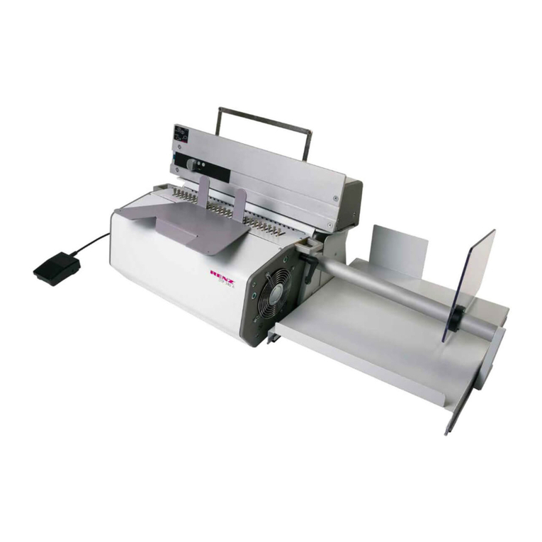
Morgana FRN 5 Manual

ISSUE 2 APRIL 1994
OPERATORS GUIDE
ROTARY NUMBERING
MACHINE
Morgana Systems Limited Snowdon Drive WinterHill
Milton Keynes Buckinghamshire MK6 1AP United
Kingdom Telephone: ( 01908 ) 608888 Facsimile:

ROTARY
PAGE 2
INTRODUCTION
ROTARY NUMBERING MACHINE

NUMBERER PAGE 3
Section.. 1 .......Installation ................................Page 4
1.1 Guards 4
1.2 Feed Bed 4
1.3 Stacker 5
Section.. 2 .......Controls ....................................Page 6
2.1 Switches 6
2.2 Knobs 7
Section.. 3 ........Setting ......................................Page 8
3.1 Feed Bed 8
3.2 Numbering 10
3.3 Numbering Digits 10
3.4 Hold Down Wheels 11
3.5 Advance Cam 12
3.6 Stacker 13
Section .4 .......Inking ......................................Page 14
4.1 Setting 14
4.2 Fitting Ink Roller to Pod 14
4.3 Fitting Ink Pod to Machine 15
4.4 Re-Inkable Ink Roller 16
4.5 Secondary Inking Position 18
Section .5 .......Make Ready ............................Page 20
Section.. 6 .......Specifications .........................Page 21
6.1 Technical Specifications 21
6.2 Spacing of Numbers 22
6.3 Sheet Sizes & Perforation Spacing 23
Section .7 .......Perforating...............................Page 24
Section.. 8 .......Slitting .....................................Page 26
Section.. 9 .......Scoring ...................................Page 27
Section.. 10 .....Maintenance ...........................Page 28
10.1 Paper Jams 28
10.2 Sensor 29
10.3 Transfer Roller 29
10.4 Numbering Head 30
10.5 Dismantling Numbering Head 31
10.6 Re-Assembling Numbering Head 33
Section.. 11 .....Troubleshooting ......................Page 34
INDEX

NUMBERER PAGE 5
Section 1
INSTALLATION
When the machine is not in use, the Feed Bed may be withdrawn
and hung on the stowage hooks.
1.3.......Stacker
The Stacker is fitted, by locating the support shafts each side into
the catch plates. Raising the end of the Stacker will allow it to fit. It
may then be lowered into position.
The height adjustment screws on each side may be positioned to
obtain the optimum height. It is recommended that only one screw
at a time (using a 5mm Allen key), is released when adjusting the
Stacker height.
When not in use, the Stacker may be hung on the stowage hooks on
the base of the machine.
With the Stacker removed,the exit guard will drop fully for the best
access to the output shafts.
NOTE...... The machine will not run with the Guards open or with the
Feed Bed removed.
Stacker Installation ....................................................Fig 1.31

ROTARY
PAGE 4
Section 1
INSTALLATION
1.1 .......Guard
The Main Guard is normally opened at the stacker end, and is
pivoted all the way over, until it rests on the feeder. The complete
guard may be removed from the machine by lifting it off it's guides,
as shown in Fig. 1.11
1.2 .......Feed Bed
The Feed Bed slots into position below the feed shaft housing
blocks. When correctly fitted, the Bed will rest flat against the
bottom edge of these blocks. The back of the Bed has to be raised
slightly, so that it can be fitted, and removed, but do not raise it too
high. Ensure that the Bed is fully forward to the stops on both
sides.
The Feed Bed will not fit, if the friction nip wheel ( Fig. 3.11 page 8 )
has been raised or lowered too far. Adjust the wheel accordingly.
Feed Bed & Guards .................................................... Fig 1.11

ROTARY
PAGE 6
Section 2 CONTROLS
2.1 .......Switches
Isolator This is the main switch to isolate the machine from the
power supply.
Motor Switches the drive on or off. If a guard is open, or the
feed bed removed, this switch will not latch. If the
guard is opened while the machine is running, this
switch will trip and stop the machine.
Feed This switch will engage the paper feed drive.
Auto/Man This switch will release the main print shaft, to allow
setting of the numbering heads.
WARNING
NEVER OPERATE THE AUTO / MAN SWITCH WHILST THE
MACHINE IS RUNNING.
Controls .................................................................... Fig 2.11

NUMBERER PAGE 7
Section 2CONTROLS
2.2.......Control Knobs
Handwheel. The handwheel is located at the rear of the
machine, and is used when setting-up.
Print position The fine adjust control which gives +7mm or -7mm
( +¼” or -¼” ) of movement to the print position.
The three rings indicate the general position of the
control and clockwise rotation will move the number
down the sheet.
One full revolution moves the print position 1mm
(3/64”) The control may be adjusted whilst the machine
is running.
Platen Pressure & Lock The printing pressure may be adjusted
as follows:-
Fit a 4mm Allen key into the lock and a 5mm Allen key
into the pressure control.
Loosen the lock and turn the pressure control, either
towards minimum or maximum, as required.
Hold the pressure control and tighten the lock, using
LIGHT pressure.
The pressure control has a small mark to indicate it's
position.
NOTE ..... It is not necessary to overtighten the lock as this can
damage the mechanism.
WARNING
ALWAYS OPERATE THE MACHINE AT THE LOWEST
PLATEN PRESSURE NECESSARY TO MAKE A
SATISFACTORY PRINT. DAMAGE TO THE MACHINE WILL
OCCUR IF EXCESSIVE PRINTING PRESSURES ARE
USED.

ROTARY
PAGE 8
3.1 .......Feed Bed
The Feed Bed is set as follows:-
-Raise the feed cover.
-Raise the primary sheet feeder.
-Loosen both side guide locks and open up the side guides, to
allow one sheet of your job to be placed on the Feed Bed.
-Paper is normally fed centrally on the machine, and setting the
near side-guide to the scales, will facilitate this. Set the inside
edge of the side guide to the scale. (See note 3 for feeding multi-
part sets with glued edge to the side).
Section 3
SETTING
Setting -Feed Bed...................................................... Fig 3.11

NUMBERER PAGE 9
Section 3
SETTING
-For odd or unknown sizes, fold the workpiece in half, along it's
length, place on the centre line, and move the near side-guide up
to the edge of the paper.
-Having set the near side-guide, set the far side-guide to the paper.
Accurate positioning of these guides is essential for reliable and
straight feeding.
-If set too tight, poor feeding will result. If set too loose,
inconsistent perforating and scoring will result, and to a lesser
extent, inconsistent numbering too.
-With both guides set, use a single piece of your work and pass it
below the friction feed tyre.
-If the work will not fit below the friction feed tyre, loosen the nip
wheel by turning the adjustment screw.
-Now tighten the nip adjustment until a very slight drag is felt on
the paper or set. The feed bed is now ready for loading with
paper.
-The paper must be spread out (shingled), so that the top sheet
approaches the friction tyre first.
-Now place the primary feeder on to the work and lower the feed
cover.
Note 1..... The scales are for guidance only, and the side guides
may have to be adjusted to obtain a straight perforation.
Note 2..... If double or multiple sheet feeding occurs, tighten the nip
adjustment.
Note 3..... For sets to be fed open edge leading, place the glued
edge nearer to the feed wheel, instead of central. Offset
by approximately 1/3 the width of the sheet.

ROTARY
PAGE 10
3.2 .......Numbering
Fit a Numbering Head to a collar, using the scale on the collar to
obtain the correct position. The scale relates to the distance from
the top of the sheet, to the top of the number. Line up the back
edge of the Numbering Head with the scale. (To make the scale
position accessible, operate the Auto/Man switch and turn the
machine using the handwheel at the rear of the machine See Fig
2.11)
Position the Numbering Head sideways, by releasing the collar
locking screw. This locking screw is only accessible by operating
the auto/man switch, (see 2.1) and rotating the machine by hand.
NOTE .....Every time the collars are moved, the advance cam will
need moving and the hold-down wheels checked , by
rotating the machine by hand. NEVER operate the
machine under power until the auto/man switch has been
released, and the Numbering Head has been turned one
complete revolution by hand, to ensure that the hold-
down wheels and advance cams are positioned correctly.
3.3 .......Setting Numbering Digits
Set the Numbering Head digit wheels using the pointed stylus,
supplied with your Numbering Head. The wheels can only be
turned in the direction shown in Fig. 3.21
To avoid having to reset the digit wheels after make-ready, set
them to a number somewhat lower than, (forward heads) or higher
than, (backward heads) your jobs required starting number.
Standard heads have seven digits. If less than seven digits are to
be printed, up to six zero's may be depressed so that they do not
print. ( This feature may not apply to all Numbering Heads )
To depress the digits, turn the digit wheel until the zero is at the top
of the head. Turn the wheel further while pressing the zero down
into the head. The zero will drop down and remain down.
To release the zero, turn the wheel further in the normal direction.
Section 3 SETTING


NUMBERER PAGE 11
Setting -Numbering Head & Hold Down Wheels..........Fig 3.21
3.4.......Hold-Down Wheels
Set the Hold-Down Wheels ( which are simply pushed into position )
so that they run on the work but will not be in the way of the
Numbering Heads.
It is important, particularly when Perforating or Slitting, that the
Hold Down Wheels are positioned equally about the centre of the
sheet. If this is not possible due to the position of the Numbering
Heads, then set one Hold Down Wheel to run on the centre of the
sheet.
NOTE...... If the Hold Down Wheels are not correctly positioned
sheets may become misaligned causing inaccurate
Perforating and possibly registration errors.
Section 3SETTING

ROTARY
PAGE 12
Setting -Advance Cam............................................... Fig 3.51
Section 3 SETTING
3.5 .......Advance cam
Set the advance cam to operate the numbering head as shown in
Fig. 3.51. Always operate the auto/man switch & rotate the
machine by hand until the numbering head is just past the cam for
setting. Position the sheet smoothers/strippers, to hold the work
flat, through the exit guard (see Fig 3.51).
WARNING
NEVER OPERATE THE MACHINE UNDER POWER UNTIL
THE AUTO/MAN SWITCH HAS BEEN RELEASED, AND
THE NUMBERING HEAD HAS BEEN TURNED ONE
COMPLETE REVOLUTION BY HAND, TO ENSURE
THAT THE HOLD-DOWN WHEELS AND ADVANCE
CAMS ARE POSITIONED CORRECTLY.

NUMBERER PAGE 13
Section 3SETTING
3.6.......Stacker
The Stacker Side Guides should be set to guide the sheets into a
neat pile. They are magnetic and are simply placed where required
but it is important to ensure that they do not come into contact with
the sheets before the sheets are free of the output shafts as this
may impair registration, particularly when perforating.
Adjust the Back Stop to allow the sheets to drop into the Stacker by
releasing its locking knob and sliding it into the required position.
For long sheets, remove the Back Stop by fully unscrewing it's
locking knob and manoeuvring it out of it’s slot. The Extensions
may now be extended to the required position after releasing their
locking knobs, which you will find under the Stacker Bed.
The sheet smoother may now be inserted into the centre slot in the
output guard. If two smoothers are required they should be
inserted into the outer slots. ( If perforating or slitting, see notes in
sections 5 & 8 ). Only use smoothers if sheets won’t stack without
them.
Setting -Stacker. ........................................................Fig 3.61

ROTARY
PAGE 14
Setting -Inking........................................................... Fig 4.11
4.1 .......Setting
Set the Ink Transfer Roller so that it runs fully over the numbering
head, by releasing it's locking screw with a 2mm Allen key.
Set the Inking Pod position by releasing it's thumb screw and
positioning it so that it inks up the Transfer Roller, in the area
above the numbering head.
Section 4 INKING
4.2 .......Fitting Ink Roller to Pod
The Inking Pod Assembly may be removed from the machine by
removing the locking thumb screw and lifting the Pod off the shaft.
There are two types of Ink Roller available, the standard preloaded
type and a re-inkable type. The Ink Roller may be replaced by
removing the ink roller screw, (see Fig 4.21) using a 4mm Allen key.

NUMBERER PAGE 15
4.3.......Re-fitting the Inking Pod
To re-fit the Inking Pod Assembly to the machine, slot it over the
locking collar and rotate the collar until the screw hole is visible
through the hole in the Ink Pod. Fit the locking screw and tighten.
When not in use, the Inking Pod Assemblies may be supported on
the sides of the machine. Re-inkable rollers MUST ALWAYS be
stored at the side when not in use, to prevent a flat spot occurring
on the roller. (see 4.4 on page 16)
The ink used in the pre-loaded ink rollers will not dry out when not
in use and therefore does not need special storage requirements.
NOTE...... Do not attempt to re-ink preloaded ink rollers
Re-inkable rollers will dry out and harden if not used regularly. If
drying out or hardening occurs, renew the Ink Roller.
Section 4INKING
Fitting Ink Wheel to Pod ..............................................Fig 4.21

ROTARY
PAGE 16
4.4 .......Re-Inkable roller
The inking system may be fitted with an optional Re-Inkable Roller
which if inked using the red and black inks developed for the
purpose, can give excellent results.
NOTE......Only use ink which has been supplied by your dealer
specifically for this system The ink formulation has been
carefully balanced to ensure optimum liquidity coupled
with a fast absorption capacity to ensure that it does not
dry out too quickly on the roller but does dry quickly once
in contact with the paper.
The following procedure should be used for loading the roller with
ink:
1. Squeeze 5 ml (a teaspoonful) ribbon of ink from the 30ml tube
of ink supplied, on to a metal plate. The plate should be at
least 300mm (12" ) long.
2. Install the roller into the inking pod (see section 4.2) and,
holding the pod firmly, roll the assembly over the ink from one
end of the plate to the other, as many times as necessary to
ensure that the ink is evenly distributed over the entire
circumference and width of the roller.
3. Allow the roller to stand for at least 8 hours (the pod may be
turned upside down and placed on a convenient non-slip
surface or installed on to the machine and stacked against the
sideframe) to allow the ink to penetrate the surface of the
cover and then re-ink the roller carrying out the procedure
described above. Less ink will be required this time.
Our tests have shown that approximately two hours of continuous
use can be achieved before re-inking becomes necessary and that
after subsequent re-filling longer time spans can be achieved. This
would indicate that the full capacity of the roller may not be
reached until several re-inking cycles have been carried out .
Section 4 INKING

NUMBERER PAGE 17
After running the inking system it is important that the pod is lifted
clear of the transfer roller and stacked on its stowage points
against the machine sideframe or removed from the machine and
placed upside down on a non-slip surface. If the roller is left in
contact with the transfer roller or left resting upon any other
surface, a flat may develop which will impair its efficiency and
make it noisy when running.
NOTE...... This re-inkable system is only recommended if you use
the machine frequently as the roller dries out and
solidifies making it impossible to re-ink if it is left without
inking for more than a week (depending on temperature).
Section 4INKING

ROTARY
PAGE 18
4.5 ......Secondary Inking Position
There are two positions for the inking assembly as shown in
Fig.4.51. The Primary Position is preferred because it allows better
access into the machine.
Both positions work equally as well but with the following
exceptions:-
-If, after setting a numbering head, it stops below or just in front of
the ink transfer roller, you must change the inking to the
alternative position. Refer to Figs 4.52 & 4.53 to establish the
exact point at which the position will need to be changed.
Failure to move the inking will cause the transfer roller to be
damaged (when the head stops below the roller), or poor quality
inking (when the head stops just before the roller).
To change from Primary to Secondary Positions or vice versa,
remove all Ink Pods, (see section 4.2) push the assembly to the
desired position, and then replace the Ink Pods. (See section 4.3)
Section 4 INKING
Primary & Secondary Inking Positions........................ Fig 4.51
PAPER DIRECTION
PRIMARY POSITION SECONDARY POSITION

NUMBERER PAGE 19
Section 4INKING
Primary Inking Position...............................................Fig 4.52
Head of Sheet
If Number Falls Within
Shaded Area, Use
Secondary Inking Position
Head of Sheet
If Number Falls Within
Shaded Area, Use
Primary Inking Position
Secondary Inking Position..........................................Fig 4.53

ROTARY
PAGE 20
5.1 ......Make ready
Having set the hold-down wheels (see note 2 below) and inking,
check the numbering position by switching on the system and
operating the feed switch, so that a sheet feeds through the
machine. (Remember to turn head by hand BEFORE switching on).
Set the stacker side-guides, back-stop and sheet smoothers (See
Fig. 3.61 and note 2 below).
If the first sheet does not print, try a second. If it still does not
print, check the platen pressure. (See section 2.2)
With one sheet numbered, it can then be seen if further adjustment
is required to the numbering head.
For sideways adjustment, operate the auto/man switch, rotate the
machine by hand and release the collar locking screw. Move the
collar as required and fully tighten the screw. For vertical
adjustment, use the print position control (See section 2.2).
NOTE 1 ...Everytime the collars are moved, check that the
numbering head will not hit the hold-down wheels or
advance cams, by operating the auto/man switch and
rotating the machine by hand.
NOTE 2 ...If you are intending to use the Perforating & Slitting
facility, it is important that particular attention is paid to
setting the Hold Down Wheels, Stacker Side Guides and
Sheet Smoothers. Any interference with the sheet whilst
it is running through the Perforating or Slitting Blades is
likely to have an adverse effect upon cutting accuracy.
Hold Down Wheels must be set on, or equally about, the
centre of the sheet and Side Guides should not touch the
sheets. You may need to experiment with the angle of the
Stacker Bed, (see section 1.3), and the position of the
Smoothers to obtain optimum results. Avoid using
Smoothers if possible.
Section 5 MAKE-READY
Table of contents
Other Morgana Office Equipment manuals
Popular Office Equipment manuals by other brands

hushoffice
hushoffice hushtwin HUS-BX-019 Maintenance and safety manual

Middle Atlantic Products
Middle Atlantic Products LD Series instruction sheet

NanaWall
NanaWall CSW75 owner's manual

Oka
Oka FrameWork MTA 0137K Assembly instructions

Evolve
Evolve EVPCP2 installation manual

ONELAN
ONELAN Reserva Edge 10T-W quick start guide