The Specialist In Drum Handling Equipment
MODEL 400A-96-124
Hydra-Lift, 96”, Air Power Lift, Manual Tilt
Operator’s Manual for Morse Hydra-Lift Karrier Model 400A-96-124
Serial Number 0409 to 1110 (MMYY)
MorseDrum.com
Copyright 2010 - Morse Mfg. Co., Inc. Form PL400A-96-124 (0409-1110) (Updated November 9, 2010 2:29 PM) 3
Machine Description
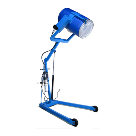
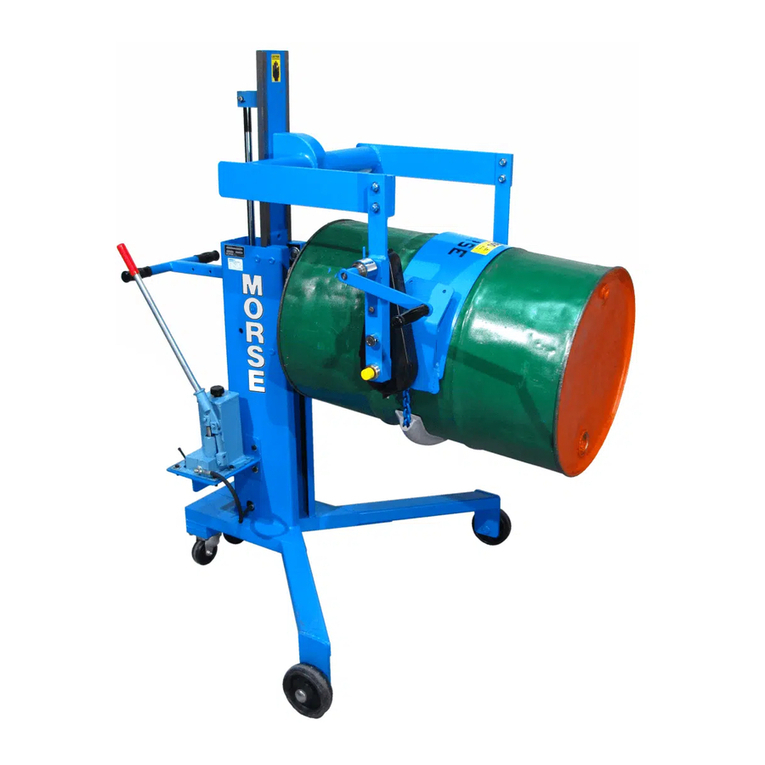
The Model 400A-96-124 Hydra-Lift Karrier will pour a drum up to 96”
high, measured from the oor to the lowest point of a horizontal drum.
It is designed to lift, transport, and dispense a 55-gallon steel or ber
drum 22” to 23.5” in diameter.
The maximum full-drum capacity is 800 Lb. The capacity is derated to
500 Lb. for a half-full drum. The half-full rating is based on the tilt mecha-
nism’s capacity for handling an unbalanced bottom-heavy drum.
Options
A smaller diameter drum can be handled with the correct size•
55/30 Series Diameter Adaptor installed (see Diameter Adaptor
literature).
The• Bracket Assembly (Part # 4556-P) is required to handle a
plastic drum without a top rim (see gure 2.1). It is also recommended
to more securely handle a ber drum. You can use the Bracket
Assembly with a 55-gallon plastic, steel or ber drum. The brace
at top and bottom of the drum prevent it from slipping lengthways
through the drum holder. It adjusts for a drum 31” to 39” tall.
The• Top Rim Clamp (Part # 4560-P) grips the upper rim of your
drum to prevent it from slipping through the drum holder (see gure
2.2). To handle a 55-gallon plastic drum with top rim, you must
install either the Bracket Assembly or the Top Rim Clamp. You can
use the Top Rim Clamp with a 55-gallon plastic, steel or ber drum
with suitable top rim.
Controls
The Morse Hydra-Lift Karrier is manually propelled and steered. The drum lift
is powered by an air motor with an on/off valve. There are two functions for the
operator to control (Figure 2.3):
1. LIFT and Lower Function to raise and lower the drum
Plug your air line into the on/off air valve.•
Turn the motor on by holding the valve handle in the on position. The drum•
will lift.
Release the valve handle when the drum is at the desired height.•
To lower the drum: With the motor off, push in the LOWER handle.•
2. TILT Function to tilt the drum
Pull down on one side of chain, rotating drum drum to the angle required •
for pouring.
For best control of drum pouring angle, pay out one side of the chain •
loop whiile pulling in the other side. This helps you to hold back the drum
rotation if contents of the drum shift.
The pull chain pin on the corner of the overhead assembly can be used•
to prevent drum rotation. Simply “tie-off” the chain by engaging it into the
pin.
If the drum handler is equipped with the MORStop Tilt-Brake, there is no •
need to hold tension on both sides of the chain loop. Braking is immediate
and self-actuating, without additional steps by the operator. To add the
MORStop Tilt-Brake to your drum handler, order part # 3900-P for a eld
installation kit.
Figure 2.3
Figure 2.2
Plastic drum being lifted
with part number 4560-P
Top Rim ClampAssembly
installed.
Figure 2.1
Plastic drum being lifted with
part number 4556-P Bracket
Assembly installed.

