morse 400A-72 User manual

The Specialist In Drum Handling Equipment
MODEL 400A-72
Hydra-Lift, 72”, Manual Lift & Tilt
MorseDrum.com
Copyright 2014 - Morse Mfg. Co., Inc. Form OM400A-72 (1210-0314) (Updated April 14, 2014 4:17 PM) 1
Contents
Page
Receiving Procedures. . . . . . . . . . . . . . . . . 1
Warranty. . . . . . . . . . . . . . . . . . . . . . . . . . . . . . . 1
Safety Information. . . . . . . . . . . . . . . . . . . . . 1 - 2
Machine Description. . . . . . . . . . . . . . . . . . . 3 - 4
Assembly Instructions. . . . . . . . . . . . . . . . . . . . 5
Operating Instructions. . . . . . . . . . . . . . . . . . 6
Maintenance. . . . . . . . . . . . . . . . . . . . . . . 6
Safety Information
While Morse Manufacturing Co. drum handling equipment is
engineered for safety and efciency, a high degree of respon-
sibility must be placed upon the machine operator to follow
safe practices, based primarily on common sense, upon which
true safety depends.
Failure to follow the safety precautions in this manual can
result in personal injury or property damage. Observe the
same precautions as with similar machinery where careless-
ness in operating or maintenance is hazardous to personnel.
Carefully read the safety precautions below and throughout
this manual.
Receiving Procedures
Every Morse drum handler is inspected prior to shipping.
However, damage may be incurred during transit.
• Check for visible damage. If you choose to accept dam-
aged freight, always sign noting the damage on the BILL
OF LADING.
• Document the damage and have the truck driver sign. We
recommend keeping a digital camera at your receiving dock
for this purpose.
• Open packages expeditiously to check the condition of the
goods. There is only a 24 hour window to notify the carrier
of any concealed damage.
• IMMEDIATELY REPORT ALL DAMAGE TO THE SHIPPING
COMPANY! Then you may contact Morse for assistance with
your freight claim.
• Morse Manufacturing will not be held responsible for any
damaged freight that is not signed for as damaged.
Delivery to non-business addresses without a loading dock
result in additional freight charges. Residential delivery fees,
inside delivery fees, re-delivery charges, and lift gate services
will be added by the truck line, and are non-negotiable.
Limited 2 Year Warranty
Morse drum handling equipment is guaranteed against defects
in workmanship or materials for TWO YEARS when used
properly within its rated capacity. Warranty does not cover
wear from normal use or damage from accident or abuse.
Motors and other purchased parts carry the warranties of their
manufacturers.
For warranty claims, contact your Morse Dealer to obtain a
return authorization number, and for return freight advice.
Return freight must be prepaid.
In all instances, liability is limited to the purchase price paid
or to repairing or replacing the product. Customer assumes
liability for any modications, unauthorized repairs or parts
substitution.
Operator’s Manual
for Morse Hydra-Lift Drum Karrier
with Manual Lift and Tilt
Model 400A-72
Serial Number 1210 to 0314 (MMYY)

The Specialist In Drum Handling Equipment
MODEL 400A-72
Hydra-Lift, 72”, Manual Lift & Tilt
Operator’s Manual for Morse Hydra-Lift Karrier with Manual Lift and Tilt
Model 400A-72 Serial Number 1210 to 0314 (MMYY)
MorseDrum.com
Copyright 2014 - Morse Mfg. Co., Inc. Form OM400A-72 (1210-0314) (Updated April 14, 2014 4:17 PM) 2
Safety Information (continued)
DANGER - Indicates a situation which, if not avoided, will result in
serious injury or death. This signal word is limited to the most extreme
situations.
WARNING - Indicates a situation which, if not avoided, could result in
serious injury or death.
CAUTION - Indicates a situation which, if not avoided, can result in
damage to the machine.
CAUTION – Do Not Transport with Drum Raised
ALWAYS LOWER THE DRUM HOLDER TO LOWEST POSITION BEFORE TRANSPORTING. The unit
can become unstable when transporting with a raised load.
DANGER - Stay Clear of Power Lines
KEEP WELL CLEAR OF POWER LINES. Never approach a power line. Current in a high voltage line
may arc some distance from the wire to the steel framed, grounded machine.
WARNING
The Hydra-Lift Karrier is designed to handle one drum of the types listed at the top of page 3, under 2.
Machine Description. DO NOT attempt to handle any other type of drum or object. DO NOT exceed
the weight capacity of 800 Lb.
WARNING - Level Floors Only
For operation only on clean, level oors of suitable bearing capacity. Do not use on sloped surfaces,
ramps, irregular or debris strewn oors.
WARNING - Do Not Modify the Unit
Under no circumstances should any modications be made to the Morse machinery without factory au-
thorization. Any modications may void the warranty. This machine was designed to perform a specic
job and alterations may result in injury to operator or machine.
WARNING - No Loose Fitting Clothing
Wear close-tting clothing and safety equipment appropriate to the job. Loose tting clothing may become
caught on the machinery and cause severe personal injury.
WARNING - Hydraulic Fluid Under Pressure Can Be Hazardous
Escaping hydraulic uid under pressure can penetrate the skin, causing serious injury. Avoid the hazard
by relieving pressure before disconnecting hydraulic lines. Keep hands and body away from pinholes
and nozzles, which eject uid under high pressure. Use a piece of cardboard to search for leaks. If an
accident occurs, see a doctor immediately and inform them of the nature of the accident.
CAUTION - Wear Safety Shoes
Wear safety shoes with non-slip soles and hard toe protection.

The Specialist In Drum Handling Equipment
MODEL 400A-72
Hydra-Lift, 72”, Manual Lift & Tilt
Operator’s Manual for Morse Hydra-Lift Karrier with Manual Lift and Tilt
Model 400A-72 Serial Number 1210 to 0314 (MMYY)
MorseDrum.com
Copyright 2014 - Morse Mfg. Co., Inc. Form OM400A-72 (1210-0314) (Updated April 14, 2014 4:17 PM) 3
Machine Description
The Model 400A-72 Hydra-Lift Karrier will pour a drum up to 72” high, mea-
sured from the oor to the lowest point of a horizontal drum. It is designed
to lift, transport, and dispense a 55-gallon steel or ber drum 22” to 23.5”
in diameter.
The maximum full-drum capacity is 800 Lb. The capacity is derated to 500
Lb. for a half-full drum. The half-full rating is based on the tilt mechanism’s
capacity for handling an unbalanced bottom-heavy drum.
Options
A smaller diameter drum can be handled with the correct size 55/30•
Series Diameter Adaptor installed (see Diameter Adaptor literature).
The adjustable Bracket Assembly (Part # 4556-P) is • required to handle
a plastic drum without a top rim (see gure 2.1). The Bracket Assembly
is also recommended when handling a ber drum. You can also use
the Bracket Assembly when handling a rimmed drum.
To handle a 55-gallon plastic drum with suitable top rim, you • must
install either the Bracket Assembly or the Top Rim Clamp (Part #
4560-P) (see gure 2.2). You can use the Top Rim Clamp to handle a
55-gallon plastic, steel or ber drum with suitable top rim.
Controls
The Morse Hydra-Lift Karrier is manually propelled and steered.
There are two functions for the operator to control (Figure 2.3):
“LIFT” and lower function for vertical positioning of the drum1.
“TILT” function to control the degree of rotation of the drum2.
LIFT and Lower Function
To raise the drum
Insert pump lever handle into pump socket.1.
With the release valve closed, begin to pump the lever handle. The drum will 2.
lift.
To lower the drum
Open the release valve slowly, a part of a turn. Allow the drum to descend at a 1.
controlled rate. The valve may be reclosed to hold the drum at any height.
TILT Function
To tilt the drum
Pull down on one side of chain, rotating drum to angle required for pouring.1.
For best control of drum pouring angle, pay out one side of the chain loop while 2.
pulling in the other side. This helps you to hold back the drum rotation if the
contents of the drum shift.
The pull chain pin on the corner of the overhead assembly can be used to3.
prevent drum rotation. Simply “tie-off” the chain by engaging in into the pin.
If the drum handler is equipped with the MORStop Tilt-Brake, there is no need 4.
to hold tension on both sides of the chain loop. Braking is immediate and
self-actuating, without additional steps by the operator. To add the MORStop
Tilt-Brake to your drum handler, order part # 3900-P for a eld installation kit.
Figure 2.3
Figure 2.2
Plastic drum being lifted
with part number 4560-P
Top Rim ClampAssembly
installed.
Figure 2.1
Plastic drum being lifted with
part number 4556-P Bracket
Assembly installed.

The Specialist In Drum Handling Equipment
MODEL 400A-72
Hydra-Lift, 72”, Manual Lift & Tilt
Operator’s Manual for Morse Hydra-Lift Karrier with Manual Lift and Tilt
Model 400A-72 Serial Number 1210 to 0314 (MMYY)
MorseDrum.com
Copyright 2014 - Morse Mfg. Co., Inc. Form OM400A-72 (1210-0314) (Updated April 14, 2014 4:17 PM) 4
WARNING - Watch Out for Pinch Points
Stay clear of moving parts. Operator should remain behind the push handle during the lift operation.
Floor Lock
The screw-down oor lock is located on the base of the tower (gure
3.1). Turning the oor lock clockwise until it locks in the down position
activates the oor lock. When the oor lock is activated it prevents
unwanted free wheeling of the unit. Floor conditions determine the
effectiveness of the oor lock. The operator should verify its holding
action before depending on it to hold.
MORcinch Drum Holder Assembly
The drum holder assembly (or “saddle assembly”) is the component
on the Hydra-Lift Karrier that is intended to hold the drum. The
MORcinch drum holder assembly is designed to secure a standard
ribbed 55-gallon steel drum around it’s middle using a cinch chain
and ratchet tightening system. The MORcinch drum holder accepts
accessories for handling a plastic drum, a ber drum, or smaller
diameter drums (see Options on pg. 3).
Figure 3.1

The Specialist In Drum Handling Equipment
MODEL 400A-72
Hydra-Lift, 72”, Manual Lift & Tilt
Operator’s Manual for Morse Hydra-Lift Karrier with Manual Lift and Tilt
Model 400A-72 Serial Number 1210 to 0314 (MMYY)
MorseDrum.com
Copyright 2014 - Morse Mfg. Co., Inc. Form OM400A-72 (1210-0314) (Updated April 14, 2014 4:17 PM) 5
Assembly Instructions
Step #1: Place tower on oor, push-handle down. See gure 1.
Step #2: Attach each leg (item 4) using two 3/8-16x3” grade 5 bolts
(item 2), at washers (item 3), and lock nuts (item 13) as shown.
Wheels should be parallel when assembled properly. See gures
1 & 2.
Please unpack and identify the following parts:
1 ea. Tower with hydraulic pump and cylinder, etc.
2 ea. Legs with wheels
1 ea. Overhead assembly with drum holder, etc.
1 ea. Package with hardware
NOTE: The clevis pins and mating surfaces at their
joints should be coated with grease during assembly.
Figure 1 Figure 2
Step #3: Tip the tower up so it stands on the casters and wheels.
Step #4: Lift overhead assembly into position. A drift pin can help align the holes. Insert a greased clevis pin (item 12) through mast cap
and boom. Install a 5/8” washer (item 9) and 3/16” roll pin (item 8) in the end of the clevis pin. See gure 3.
Step #5: Next, connect the cylinder (item 16) to the overhead assembly: Align ram eye with holes in boom clevis plates and insert a
greased clevis pin (item 12) with four 5/8” washers (item 9). Place another washer (item 9) on outer end of clevis pin and drive a 3/16” roll
pin (item 8) into the hole at the end of clevis pin. See gure 4.
Figure 3 Figure 4
Step #6: Remove sealing plug from the top of hydraulic reservoir and ll reservoir with included container of hydraulic uid. Replace seal-
ing plug with the included breather plug. Your Hydra-Lift Karrier is now ready for service. Please refer to the operating and maintenance
instructions provided.

The Specialist In Drum Handling Equipment
MODEL 400A-72
Hydra-Lift, 72”, Manual Lift & Tilt
Operator’s Manual for Morse Hydra-Lift Karrier with Manual Lift and Tilt
Model 400A-72 Serial Number 1210 to 0314 (MMYY)
MorseDrum.com
Copyright 2014 - Morse Mfg. Co., Inc. Form OM400A-72 (1210-0314) (Updated April 14, 2014 4:17 PM) 6
Operating Instructions
Push the Hydra-Lift Karrier to the drum.1.
Using the “LIFT” control as described in “Machine Description2.
- Controls” (page 3) , position the drum holder assembly with
the back band at the middle of the drum. (Figure 3.1). With the
ratchet plate swung open and the cinch chain hanging from the
chain hook, push the unit until the back band rests rmly against
the drum. Some adjustment to the tilt angle of the saddle may be
necessary to ensure band ts ush on the drum.
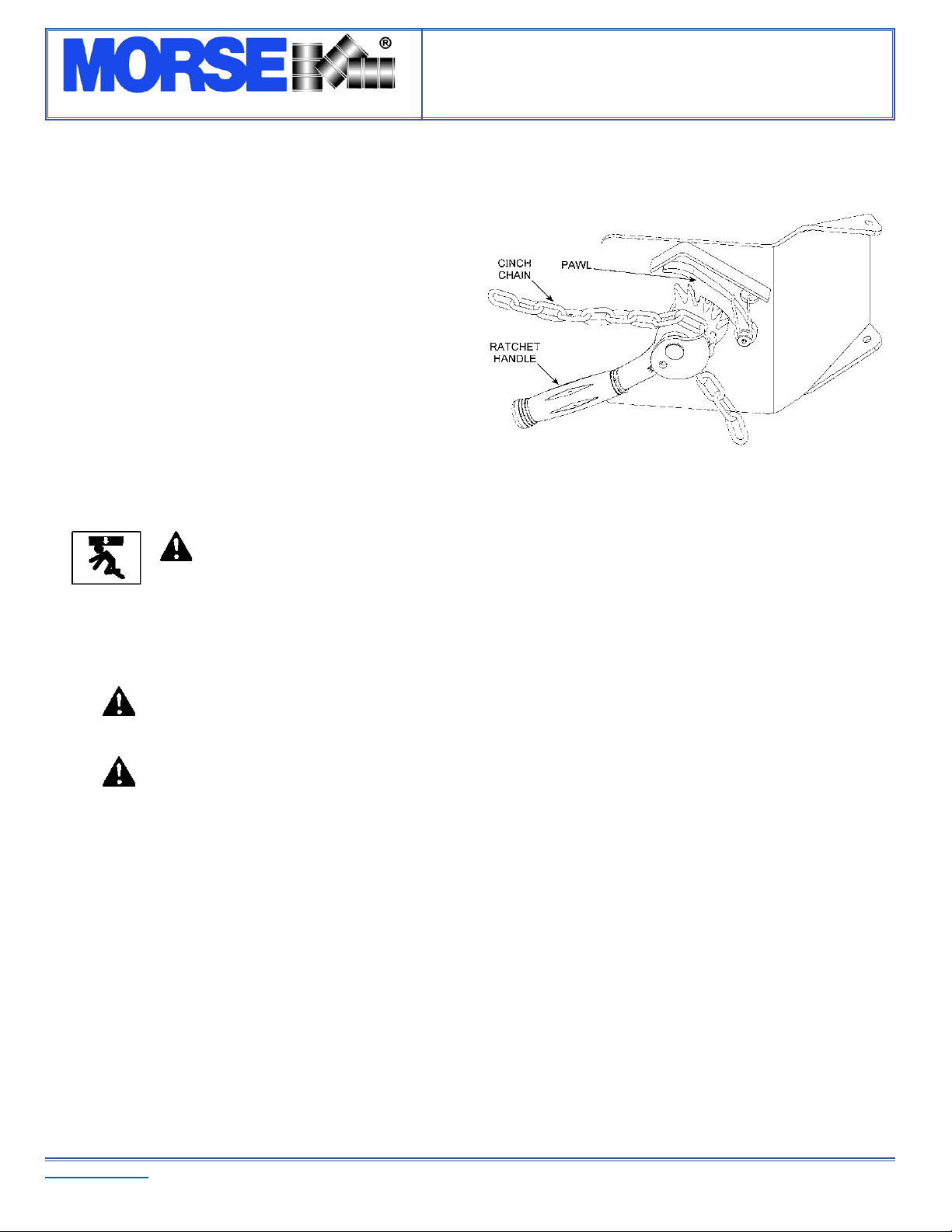
Attaching the drum: Drape the chain across the front of the drum3.
and engage a link into the slot in the ratchet (Figure 3.2). Turn
the ratchet clockwise to tighten chain. If ratchet turns until the
pawl is beyond the last ratchet tooth, turn the ratchet back and
slide the next link into the ratchet slot and try tightening again.
The chain must be held tightly against the drum with the pawl
engaged securely in the ratchet teeth.
Operate the lift function to lift drum clear of oor. Roll to 4.
dispensing location. NOTE: Do not allow the drum to impact on
oor, pouring station, etc. or a spill or damage could occur.
CAUTION – Do Not Transport with Drum Raised
ALWAYS LOWER THE DRUM HOLDER TO LOWEST POSITION BEFORE TRANSPORTING.
The unit can become unstable when transporting with a raised load.
Lift drum to desired pouring height. Operate the tilt control as described in5. “Machine Description - Controls” (page 3) to adjust the
drum attitude. This is especially important when lifting an open drum. The oor lock should be engaged while dispensing / draining.
When dispensing is complete, tilt drum back to upright position. Disengage the oor lock and lower the drum to transporting height; 6.
about 6” off the oor.
WARNING - Stay Clear of Raised Drum
NEVER allow anyone to be below any part of a raised drum handler or drum. Remain behind the
push handle while handling a drum.
WARNING – Do NOT Disengage the Cinch Chain When Drum is off the Ground
When the drum is in the upright position, lower the drum to the oor before releasing the cinch chain.
Push the unit to the drum storage area and lower to the oor in an upright position. Release the cinch chain from the ratchet by 7.
applying pressure to the ratchet handle in a clockwise direction with one hand and opening the pawl to free the ratchet with the other
hand. Remove the cinch chain link from the ratchet.
Maintenance
Periodic inspection for the general condition of structural and mechanical components is imperative for safe and efcient operation.•
Periodically inspect all moving parts, framework, and contact areas for signs of wear, fatigue, or loosening. Tighten, adjust, or •
replace parts as necessary to prevent failure and maintain proper function.
Inspect the hydraulic system for oil drips, hose damage, or other signs of wear. Inspect the level and condition of the hydraulic uid. •
Replace any parts that show signs of wear.
Grease wheel bearings periodically. Oil or grease all moving parts including: the three clevis pins and the surfaces of the boom which•
contact the inside of the mast cap, the hinge pin, the gears and sprockets in the tilt drive, and the ratchet and pawl.
Worn or damaged parts must be properly replaced with the correct, genuine Morse parts.•
Hydraulic pump should be lled with the provided quart of Mobil ATF D/M (Morse part # 3983-P). Material safety data sheet (MSDS) •
is available online. Change oil yearly, sooner depending on dirty conditions or outdoor use.
Figure 3.2
Other manuals for 400A-72
2
This manual suits for next models
2
Table of contents
Other morse Storage manuals

morse
morse 82A-SS User manual

morse
morse 0309 User manual

morse
morse 0409 User manual

morse
morse 0409 User manual

morse
morse 400A-60-124 User manual

morse
morse 515M-T User manual

morse
morse 82A-125 User manual

morse
morse MORSPEED 1000 User manual

morse
morse MORCINCH 4556SS-P User manual

morse
morse 185R User manual

morse
morse 311 Series User manual

morse
morse 400AM-96-124 User manual

morse
morse 80i User manual

morse
morse 400A-96-124 User manual

morse
morse 410-120 User manual

morse
morse 185HD SERIES User manual

morse
morse 285XGR User manual

morse
morse 185XGR User manual

morse
morse MORCINCH 4556-P User manual

morse
morse 1110 User manual


