Morso 7870 User manual

DK Montering af væghængt Morsø 7870/7970
DE Installation des Wandofens Morsø 7870/7970
UK Installation of wall-hung Morsø 7870/7970
NO Montere vegghengt Morsø 7870/7970
SV Montering av vägghängd Morsø 7870/7970
FR Installation murale du Morsø 7870/7970
NL Plaatsing van de wandkachel Morsø 7870/7970
SP Instalación de la estufa Morsø 7870/7970 de pared
IT Installazione a parete della stufa Morsø 7870/7970
Morsø 7870/7970
MORSØ JERNSTØBERI A/S . DK-7900 NYKØBING MORS
E-Mail: stoves@morsoe.com · Website: www.morsoe.com

2
Min.275 mm
Min. 11"
Min. 854 mm
Min. 33 5/8"
Revisions
Rev.
Sign.:
Title:
Drawing no.:
Dim. without indication of margin acc. to DS/ISO 2768-1 m
1:6
Monteringsvejledning
Væghængt
Morsø 7900
RSV
2011.09.07
A2
Date of print: 22-01-2013
U:\udv\Tegninger\7900\7900 Assembly.SLDASM
7900-108
Itemno.:
This drawing is Morsø Jernstøberi A/S' property and must not be sold, lended or copied without any written authorization from the company.
Material:
Weight kg.:
Model no.
Drawingtype:
Location of file:
Scale:
Format:
Released:
Construction:
Date:
Montering af væghængt Morsø 7800/7970
Vægbeslaget er leveret med 8 huller til montering af
ekspansionsbolte i muren. Minimum 4 af de 8 huller i
vægbeslaget skal anvendes i forbindelse med fastgø-
relsen på væggen.
Boltene skal dimensioneres, så man er sikker på, at
muren og det materiale den er udført i, er i stand
til at holde ovnen. Ovnens egenvægt er 135 kg. Det
påhviler derfor installatør/kunde at sikre sig at væg/
skorsten på forsvarlig vis kan bære ovnen. Vi gør op-
mærksom på, at elementskorstene samt murede ½
stens skorstene uden foring ikke altid har den nød-
vendige bæreevne. Er De i tvivl skal De derfor kon-
takte en fagmand.
Vægbeslaget kan benyttes som boreskabelon. Mini-
mum afstand til brændbart gulv er 275 mm.
Bemærk, der må ikke anvendes rawplugs af plastik
på grund af varmepåvirkningen.
En murbøsning indmures korrekt i væggen, hvis
røgafgangen ønskes bagud (se skitse) og vægbesla-
get monteres på væggen.
Efter udpakning af basisovnen tages løsdelene ud af
ovnen. Askeskuen, den nederste røgledeplade der
er udført i vermiculite, den støbte rist og mellembund
ernes.
Stråleskærmen på bagsiden
af ovnen skrues af og skal
ikke anvendes på den væg-
hængte udgave.
Min.275 mm
Min. 11"
Min. 854 mm
Min. 33 5/8"
Revisions
Rev.
Sign.:
Title:
Drawing no.:
Dim. without indication of margin acc. to DS/ISO 2768-1 m
1:6
Monteringsvejledning
Væghængt
Morsø 7900
RSV
2011.09.07
A2
Date of print: 22-01-2013
U:\udv\Tegninger\7900\7900 Assembly.SLDASM
7900-108
Itemno.:
This drawing is Morsø Jernstøberi A/S' property and must not be sold, lended or copied without any written authorization from the company.
Material:
Weight kg.:
Model no.
Drawingtype:
Location of file:
Scale:
Format:
Released:
Construction:
Date:

32
De to skruer, der lukker hullerne øverst afmonteres (se skitse) og monteres igen nederst for
at lukke hullerne, der har været anvendt til fastgørelse af stråleskærmen.
På bagsiden af ovnen monteres de to vinkelbeslag med de medfølgende 4 stk. skiver og
skruer.
Basisovnen løftes på plads, så den støtter
på bunden af vægbeslaget. Ovnen fast-
gøres med de medfølgende 2 stk. M6x12
skruer i toppen og 2 stk. M8x20 skruer
og skiver i bunden (se skitse). Det anbe-
fales at være 2 personer til dette arbejde.
Min.275 mm
Min. 11"
Min. 854 mm
Min. 33 5/8"
Revisions
Rev.
Sign.:
Title:
Drawing no.:
Dim. without indication of margin acc. to DS/ISO 2768-1 m
1:6
Monteringsvejledning
Væghængt
Morsø 7900
RSV
2011.09.07
A2
Date of print: 22-01-2013
U:\udv\Tegninger\7900\7900 Assembly.SLDASM
7900-108
Itemno.:
This drawing is Morsø Jernstøberi A/S' property and must not be sold, lended or copied without any written authorization from the company.
Material:
Weight kg.:
Model no.
Drawingtype:
Location of file:
Scale:
Format:
Released:
Construction:
Date:

4
Min.275 mm
Min. 11"
Min. 854 mm
Min. 33 5/8"
Revisions
Rev.
Sign.:
Title:
Drawing no.:
Dim. without indication of margin acc. to DS/ISO 2768-1 m
1:6
Monteringsvejledning
Væghængt
Morsø 7900
RSV
2011.09.07
A2
Date of print: 22-01-2013
U:\udv\Tegninger\7900\7900 Assembly.SLDASM
7900-108
Itemno.:
This drawing is Morsø Jernstøberi A/S' property and must not be sold, lended or copied without any written authorization from the company.
Material:
Weight kg.:
Model no.
Drawingtype:
Location of file:
Scale:
Format:
Released:
Construction:
Date:
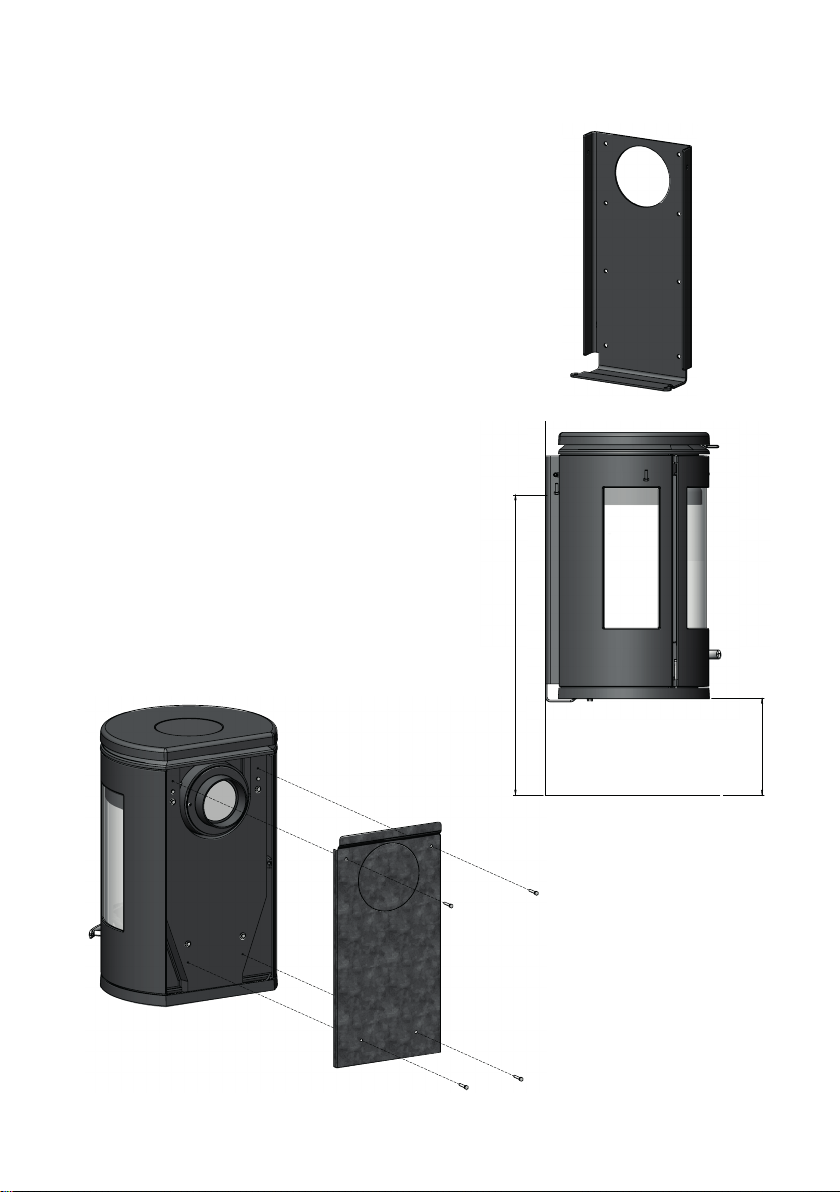
Installation des Wandofens Morsø 7800/7970
Die Wandauängung wird mit 8 Löchern zur Befestig-
ung an der Wand mit Ankerbolzen geliefert. Mindestens
4 der 8 Löcher in der Wandauängung müssen verwen-
det werden, um den Ofen an der Wand zu befestigen.
Die Bolzen müssen so bemessen sein, dass die Wand
und das Material, aus dem sie gemacht ist, den Ofen
halten können. Das Eigengewicht des Ofens beträgt 135
kg. Der Einbauer/Kunde muss deshalb sicherstellen, dass
die Wand/der Schornstein den Ofen angemessen halten
kann. Beachten Sie, dass Elementschornsteine und ge-
mauerten Halbstein-Schornsteine nicht immer die erfor-
derliche Tragfähigkeit haben. Wenn Sie sich nicht sicher
sind, sollten Sie sich deshalb an einen Fachmann wenden.
Die Wandauängung kann als Bohrschablone verwen-
det werden. Der Mindestabstand zu brennbarem Boden
beträgt 275 mm.
Beachten Sie, dass Plastikdübel aufgrund der Einwir-
kungen der Hitze nicht verwendet werden dürfen.
Eine Mauerbuchse muss korrekt in die Wand eingebaut
werden, wenn der Rauchabzug nach hinten gewünscht
wird (siehe Abbildung), und die Wandauängung muss
an der Wand angebracht werden.
Nach dem Auspacken des Basisofens, die losen Teile aus
dem Ofen nehmen. Die Ascheschublade, die untere Rau-
chleitplatte aus Vermiculit, der gusseiserne Rost und die
Zwischenplatte müssen herausgenommen werden.
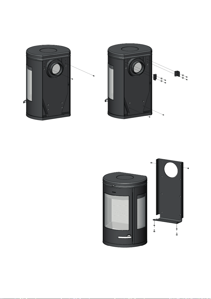
Der Hitzeschild auf der
Rückseite des Ofens muss
abgeschraubt werden und
darf bei einem Wandofen
nicht verwendet werden.
Min.275 mm
Min. 11"
Min. 854 mm
Min. 33 5/8"
Revisions
Rev.
Sign.:
Title:
Drawing no.:
Dim. without indication of margin acc. to DS/ISO 2768-1 m
1:6
Monteringsvejledning
Væghængt
Morsø 7900
RSV
2011.09.07
A2
Date of print: 22-01-2013
U:\udv\Tegninger\7900\7900 Assembly.SLDASM
7900-108
Itemno.:
This drawing is Morsø Jernstøberi A/S' property and must not be sold, lended or copied without any written authorization from the company.
Material:
Weight kg.:
Model no.
Drawingtype:
Location of file:
Scale:
Format:
Released:
Construction:
Date:

54
Die beiden Schrauben, mit denen die oberen Löcher verschlossen sind (siehe Abbildung)
müssen entfernt und unten wieder eingeschraubt werden, um die Löcher zu schließen, mit
denen der Hitzeschild befestigt wurde.
Die beiden Winkelbefestigungen müssen an der Rückseite des Ofens mit den mitgelieferten
Unterlegscheiben Nr. 4 und Schrauben befestigt werden.
Der Basisofen wird an seinen Platz geho-
ben, so dass er auf dem Boden der Wan-
dauängung zu sitzen kommt. Der Ofen
muss mit den mitgelieferten zwei M5x12
Schrauben oben und den mitgelieferten
zwei M8x20 Schrauben und Unterlegs-
cheiben am Boden befestigt werden
(siehe Abbildung). Wir empfehlen, diese
Arbeiten mit zwei Personen auszuführen.
Min.275 mm
Min. 11"
Min. 854 mm
Min. 33 5/8"
Revisions
Rev.
Sign.:
Title:
Drawing no.:
Dim. without indication of margin acc. to DS/ISO 2768-1 m
1:6
Monteringsvejledning
Væghængt
Morsø 7900
RSV
2011.09.07
A2
Date of print: 22-01-2013
U:\udv\Tegninger\7900\7900 Assembly.SLDASM
7900-108
Itemno.:
This drawing is Morsø Jernstøberi A/S' property and must not be sold, lended or copied without any written authorization from the company.
Material:
Weight kg.:
Model no.
Drawingtype:
Location of file:
Scale:
Format:
Released:
Construction:
Date:

6
Min.275 mm
Min. 11"
Min. 854 mm
Min. 33 5/8"
Revisions
Rev.
Sign.:
Title:
Drawing no.:
Dim. without indication of margin acc. to DS/ISO 2768-1 m
1:6
Monteringsvejledning
Væghængt
Morsø 7900
RSV
2011.09.07
A2
Date of print: 22-01-2013
U:\udv\Tegninger\7900\7900 Assembly.SLDASM
7900-108
Itemno.:
This drawing is Morsø Jernstøberi A/S' property and must not be sold, lended or copied without any written authorization from the company.
Material:
Weight kg.:
Model no.
Drawingtype:
Location of file:
Scale:
Format:
Released:
Construction:
Date:
Installation of wall-hung Morsø 7800/7970
The wall mounting is supplied with 8 holes for xing
to the wall with expanding bolts. A minimum of 4 of
the 8 holes in the wall mounting must be used to x
the oven to the wall.
The bolts must be sized to ensure that the wall and
the material it is made of are capable of suppor-
ting the oven. The self weight of the oven is 135
kg. The installer/ client must therefore ensure that
the wall/ chimney can support the oven in an appro-
priate manner. Note that unit chimneys and unlined
½ brick chimneys do not always have the necessary
load-bearing capacity. If you are in any doubt, you
should therefore contact a qualied person.
The wall mounting may be used as a drilling template.
The minimum clearance to a ammable oor is 275 mm.
Note that plastic wall plugs must not be used
because of the eects of heat.
A wall bushing must be built in correctly to the wall
if a rear smoke outlet is wanted (see sketch) and the
wall mounting must be tted to the wall.
After unpacking the basic oven, remove the loose
parts of the oven. The ash drawer, the lower smoke
bae made of vermiculite, the cast grate and the
intermediate base should be removed.
The heat screen on the
rear of the oven must be
screwed o and must not
be used with the wall-hung
version.
Min.275 mm
Min. 11"
Min. 854 mm
Min. 33 5/8"
Revisions
Rev.
Sign.:
Title:
Drawing no.:
Dim. without indication of margin acc. to DS/ISO 2768-1 m
1:6
Monteringsvejledning
Væghængt
Morsø 7900
RSV
2011.09.07
A2
Date of print: 22-01-2013
U:\udv\Tegninger\7900\7900 Assembly.SLDASM
7900-108
Itemno.:
This drawing is Morsø Jernstøberi A/S' property and must not be sold, lended or copied without any written authorization from the company.
Material:
Weight kg.:
Model no.
Drawingtype:
Location of file:
Scale:
Format:
Released:
Construction:
Date:

76
The two screws that seal the upper holes must be removed (see sketch) and installed again
below to seal the holes that were used to x the heat screen.
The two angle xings must be tted on the rear of the oven using the 4 no. washers and
screws supplied.
The basic oven is lifted into place, so
that its sits on the bottom of the wall
mounting. The oven must be xed using
the 2 pcs. M5x12 screws supplied at the
top and the 2 pcs. M8x20 screws and
washers supplied at the bottom (see
sketch). We recommended that 2 per-
sons should carry out this work.
Min.275 mm
Min. 11"
Min. 854 mm
Min. 33 5/8"
Revisions
Rev.
Sign.:
Title:
Drawing no.:
Dim. without indication of margin acc. to DS/ISO 2768-1 m
1:6
Monteringsvejledning
Væghængt
Morsø 7900
RSV
2011.09.07
A2
Date of print: 22-01-2013
U:\udv\Tegninger\7900\7900 Assembly.SLDASM
7900-108
Itemno.:
This drawing is Morsø Jernstøberi A/S' property and must not be sold, lended or copied without any written authorization from the company.
Material:
Weight kg.:
Model no.
Drawingtype:
Location of file:
Scale:
Format:
Released:
Construction:
Date:

8
Min.275 mm
Min. 11"
Min. 854 mm
Min. 33 5/8"
Revisions
Rev.
Sign.:
Title:
Drawing no.:
Dim. without indication of margin acc. to DS/ISO 2768-1 m
1:6
Monteringsvejledning
Væghængt
Morsø 7900
RSV
2011.09.07
A2
Date of print: 22-01-2013
U:\udv\Tegninger\7900\7900 Assembly.SLDASM
7900-108
Itemno.:
This drawing is Morsø Jernstøberi A/S' property and must not be sold, lended or copied without any written authorization from the company.
Material:
Weight kg.:
Model no.
Drawingtype:
Location of file:
Scale:
Format:
Released:
Construction:
Date:
Montere vegghengt Morsø 7800/7970
Veggbeslaget leveres med 8 hull til montering av
ekspansjonsskruer i muren. Minst 4 av de 8 hullene
i veggbeslaget skal brukes i forbindelse med festing
på veggen.
Skruene skal dimensjoneres slik at man er sikker på
at muren og materialet den er laget av er i stand til å
holde ovnen. Ovnens egenvekt er 135 kg. Det er der-
for installatørens/kundens ansvar å sikre at veggen/
pipa kan bære ovnen på forsvarlig måte. Vi gjør opp-
merksom på at elementpiper samt murte halvsteinspi-
per uten fôring ikke alltid har den nødvendige bæreev-
nen. Ta kontakt med en fagperson dersom du er i tvil.
Veggbeslaget kan benyttes som boresjablong. Mini-
mumsavstand til brennbart gulv er 275 mm.
Vær oppmerksom på at det ikke må brukes
rawplugger av plast på grunn av varmeutviklingen.
En murbøssing skal mures korrekt inn i veggen der-
som røykutløpet ønskes på baksiden (se tegningen)
og veggbeslaget monteres på veggen.
Ta ut de løse delene fra ovnen etter at basisovnen er
pakket ut. Fjern askeskuen, den nederste røyklede-
platen som er laget av vermikulitt, den støpte risten
samt mellomplaten.
Stråleskjermen på baksiden
av ovnen skal skrus av og
ikke brukes på den vegg-
monterte utgaven.
Min.275 mm
Min. 11"
Min. 854 mm
Min. 33 5/8"
Revisions
Rev.
Sign.:
Title:
Drawing no.:
Dim. without indication of margin acc. to DS/ISO 2768-1 m
1:6
Monteringsvejledning
Væghængt
Morsø 7900
RSV
2011.09.07
A2
Date of print: 22-01-2013
U:\udv\Tegninger\7900\7900 Assembly.SLDASM
7900-108
Itemno.:
This drawing is Morsø Jernstøberi A/S' property and must not be sold, lended or copied without any written authorization from the company.
Material:
Weight kg.:
Model no.
Drawingtype:
Location of file:
Scale:
Format:
Released:
Construction:
Date:

98
Ta ut de to skruene som dekker hullene øverst (se tegningen) og monter dem igjen nederst
for å dekke hullene som ble brukt til å feste stråleskjermen.
Monter de to vinkelbeslagene på baksiden av ovnen med de 4 medfølgende skivene og
skruene.
Løft basisovnen på plass slik at den støt-
tes på bunnen av veggbeslaget.
Fest ovnen med de 2 medfølgende
M5×12-skruene øverst og de medfølgen-
de skivene og 2 M5×12-skruene nederst
(se tegningen). Det anbefales at 2 perso-
ner utfører dette arbeidet.
Min.275 mm
Min. 11"
Min. 854 mm
Min. 33 5/8"
Revisions
Rev.
Sign.:
Title:
Drawing no.:
Dim. without indication of margin acc. to DS/ISO 2768-1 m
1:6
Monteringsvejledning
Væghængt
Morsø 7900
RSV
2011.09.07
A2
Date of print: 22-01-2013
U:\udv\Tegninger\7900\7900 Assembly.SLDASM
7900-108
Itemno.:
This drawing is Morsø Jernstøberi A/S' property and must not be sold, lended or copied without any written authorization from the company.
Material:
Weight kg.:
Model no.
Drawingtype:
Location of file:
Scale:
Format:
Released:
Construction:
Date:

10
Min.275 mm
Min. 11"
Min. 854 mm
Min. 33 5/8"
Revisions
Rev.
Sign.:
Title:
Drawing no.:
Dim. without indication of margin acc. to DS/ISO 2768-1 m
1:6
Monteringsvejledning
Væghængt
Morsø 7900
RSV
2011.09.07
A2
Date of print: 22-01-2013
U:\udv\Tegninger\7900\7900 Assembly.SLDASM
7900-108
Itemno.:
This drawing is Morsø Jernstøberi A/S' property and must not be sold, lended or copied without any written authorization from the company.
Material:
Weight kg.:
Model no.
Drawingtype:
Location of file:
Scale:
Format:
Released:
Construction:
Date:
Montering av vägghängd Morsø 7800/7970
Väggfästet levereras med åtta hål för montering av
expanderskruvar i väggen. Minst fyra av de åtta hålen
i väggen måste användas för väggmontering.
Bultarna måste dimensioneras så att du kan vara
säker på att väggen och materialet som den är
gjord av kan hålla kaminen. Kaminen väger 135
kg. Det är därför installatörens/kundens ansvar att
säkerställa att väggen/skorstenen kan bära kaminen.
Observera att elementskorstenar och murade halv-
stenskorstenar utan foder inte alltid har den bärför-
måga som krävs. Om du är osäker bör du kontakta
en fackman.
Väggfästet kan användas som borrmall. Minsta avst-
ånd till brännbart golv är 275 mm.
Observera att man inte får använda skruvpluggar
av plast på grund av värmepåverkan.
Mura in en väggenomföring ordentligt i väggen om
du vill ha rökkanalen bakåt (se skiss) och montera
väggfästet på väggen.
Ta ut de lösa delarna ur kaminen när du packat upp
baskaminen. Avlägsna asklådan, den nedre baeln
som är tillverkad av vermikulit, det gjutna gallret och
mellanbotten.
Skruva av strålskärmen på
baksidan av kaminen efter-
som den inte ska användas
på den väggmonterade ver-
sionen.
Min.275 mm
Min. 11"
Min. 854 mm
Min. 33 5/8"
Revisions
Rev.
Sign.:
Title:
Drawing no.:
Dim. without indication of margin acc. to DS/ISO 2768-1 m
1:6
Monteringsvejledning
Væghængt
Morsø 7900
RSV
2011.09.07
A2
Date of print: 22-01-2013
U:\udv\Tegninger\7900\7900 Assembly.SLDASM
7900-108
Itemno.:
This drawing is Morsø Jernstøberi A/S' property and must not be sold, lended or copied without any written authorization from the company.
Material:
Weight kg.:
Model no.
Drawingtype:
Location of file:
Scale:
Format:
Released:
Construction:
Date:

1110
Avlägsna de två skruvarna som täpper till hålen högst upp (se skiss) och montera dem i bot-
ten för att täppa till hålen som har använts för att fästa strålskärmen.
Montera de två vinkelfästena med de medföljande fyra brickorna och skruvarna på baksidan
av kaminen.
Lyft baskaminen på plats så att den vilar
nere på väggfästet.
Kaminen fästs med de medföljande två
M5x12 skruvarna upptill och de medföl-
jande två M8x20 skruvarna och brickor-
na på undersidan (se skiss). Det rekom-
menderas att man är två personer för
detta arbete.
Min.275 mm
Min. 11"
Min. 854 mm
Min. 33 5/8"
Revisions
Rev.
Sign.:
Title:
Drawing no.:
Dim. without indication of margin acc. to DS/ISO 2768-1 m
1:6
Monteringsvejledning
Væghængt
Morsø 7900
RSV
2011.09.07
A2
Date of print: 22-01-2013
U:\udv\Tegninger\7900\7900 Assembly.SLDASM
7900-108
Itemno.:
This drawing is Morsø Jernstøberi A/S' property and must not be sold, lended or copied without any written authorization from the company.
Material:
Weight kg.:
Model no.
Drawingtype:
Location of file:
Scale:
Format:
Released:
Construction:
Date:

12
Min.275 mm
Min. 11"
Min. 854 mm
Min. 33 5/8"
Revisions
Rev.
Sign.:
Title:
Drawing no.:
Dim. without indication of margin acc. to DS/ISO 2768-1 m
1:6
Monteringsvejledning
Væghængt
Morsø 7900
RSV
2011.09.07
A2
Date of print: 22-01-2013
U:\udv\Tegninger\7900\7900 Assembly.SLDASM
7900-108
Itemno.:
This drawing is Morsø Jernstøberi A/S' property and must not be sold, lended or copied without any written authorization from the company.
Material:
Weight kg.:
Model no.
Drawingtype:
Location of file:
Scale:
Format:
Released:
Construction:
Date:
Installation murale du Morsø 7800/7970
Des orices dans la structure de xation murale permet-
tent de monter les boulons expandeurs à visser dans le
mur. Au minimum quatre des huit orices doivent être
utilisés pour xer le poêle sur le mur.
La taille des boulons et le matériau du mur doivent
pouvoir supporter le poids du poêle. À vide, le poêle
pèse 135 kg. Par conséquent l’installateur ou le client
doit vérier que le mur/ cheminée est capable de por-
ter le poids du poêle. Veuillez tenir compte du fait que
certains systèmes de cheminée et des cheminées en de-
mi-briques sans doublure n’ont pas la capacité porteuse
nécessaire pour ce type de montage. En cas de doute,
consultez un professionnel.
La structure de xation murale peut être utilisée comme
patron pour marquer la position des orices à percer
dans le mur. La distance minimale entre le poêle et un sol
combustible est de 275 mm.
N’utilisez pas de chevilles en plastique, car elles ne ré-
sisteraient pas à la chaleur du poêle.
Une traversée murale appropriée doit être construite
dans le mur si l’évacuation des fumées se fait par l’arrière
du poêle (voir schéma) et la structure de xation murale
doit être correctement xée au mur.
Après avoir déballé le poêle, retirez les éléments séparés.
Sortez le tiroir à cendres, le déecteur inférieur en ver-
miculite, la grille en fonte et la base intermédiaire.
L’écran thermique doit
être dévissé de l’arrière du
poêle et ne doit pas être
utilisé avec une installation
murale.
Min.275 mm
Min. 11"
Min. 854 mm
Min. 33 5/8"
Revisions
Rev.
Sign.:
Title:
Drawing no.:
Dim. without indication of margin acc. to DS/ISO 2768-1 m
1:6
Monteringsvejledning
Væghængt
Morsø 7900
RSV
2011.09.07
A2
Date of print: 22-01-2013
U:\udv\Tegninger\7900\7900 Assembly.SLDASM
7900-108
Itemno.:
This drawing is Morsø Jernstøberi A/S' property and must not be sold, lended or copied without any written authorization from the company.
Material:
Weight kg.:
Model no.
Drawingtype:
Location of file:
Scale:
Format:
Released:
Construction:
Date:

1312
Les deux vis qui ferment les deux orices supérieurs doivent être retirées (voir schéma) et
vissées dans les orices de xation de l’écran thermique.
Les deux équerres de xation doivent être montées à l’arrière du poêle avec les quatre vis
et rondelles fournies.
Soulevez le poêle pour le poser sur la
partie inférieure de la structure de xa-
tion. Fixez la partie supérieure du poêle
avec les deux vis M5x12 fournies, puis
avec les deux vis M8x20 et rondelles
fournies pour la partie inférieure (voir
schéma). L’installation doit être réalisée
par deux personnes.
Min.275 mm
Min. 11"
Min. 854 mm
Min. 33 5/8"
Revisions
Rev.
Sign.:
Title:
Drawing no.:
Dim. without indication of margin acc. to DS/ISO 2768-1 m
1:6
Monteringsvejledning
Væghængt
Morsø 7900
RSV
2011.09.07
A2
Date of print: 22-01-2013
U:\udv\Tegninger\7900\7900 Assembly.SLDASM
7900-108
Itemno.:
This drawing is Morsø Jernstøberi A/S' property and must not be sold, lended or copied without any written authorization from the company.
Material:
Weight kg.:
Model no.
Drawingtype:
Location of file:
Scale:
Format:
Released:
Construction:
Date:

14
Min.275 mm
Min. 11"
Min. 854 mm
Min. 33 5/8"
Revisions
Rev.
Sign.:
Title:
Drawing no.:
Dim. without indication of margin acc. to DS/ISO 2768-1 m
1:6
Monteringsvejledning
Væghængt
Morsø 7900
RSV
2011.09.07
A2
Date of print: 22-01-2013
U:\udv\Tegninger\7900\7900 Assembly.SLDASM
7900-108
Itemno.:
This drawing is Morsø Jernstøberi A/S' property and must not be sold, lended or copied without any written authorization from the company.
Material:
Weight kg.:
Model no.
Drawingtype:
Location of file:
Scale:
Format:
Released:
Construction:
Date:
Plaatsing van de wandkachel Morsø 7800/7970
De wandkachel is voorzien van 8 gaten voor wand-
bevestiging met ankerbouten. U moet ten minste 4
van deze 8 gaten gebruiken om de kachel tegen de
wand te bevestigen.
Zorg ervoor dat de ankerbouten geschikt zijn voor
de wand en het materiaal waaruit hij is gemaakt,
zodat ze de kachel kunnen dragen. Het eigen ge-
wicht van de kachel bedraagt 135 kg. De installateur
/ klant moet garanderen dat de wand / schoorsteen
de kachel veilig kan dragen. Merk op dat schoorste-
nen opgetrokken in blokelementen en niet-beplei-
sterde, gedeeltelijk in baksteen opgetrokken scho-
orstenen niet altijd voldoende draagkracht hebben.
Raadpleeg daarom bij twijfel een vakman.
Het wandmontageframe kan worden gebruikt als bo-
orsjabloon. De minimale afstand tot een brandbare
ondergrond bedraagt 275 mm.
Gebruik geen wandpluggen omwille van de eec-
ten door de warmte.
Bouw wandbuizen correct in indien u de rookuitlaat
aan de achterzijde gebruikt (zie tekening). Bevestig
het wandmontageframe tegen de wand.
Verwijder, na het uitpakken van de eigenlijke kachel,
de losse onderdelen. De aslade, het vermiculieten
rookschot, het gietijzeren rooster en de tussenbasis
moeten worden verwijderd.
Het hittescherm aan de
achterzijde van de kachel
moet worden losgeschro-
efd. Gebruik dit niet bij
wandmontage.
Min.275 mm
Min. 11"
Min. 854 mm
Min. 33 5/8"
Revisions
Rev.
Sign.:
Title:
Drawing no.:
Dim. without indication of margin acc. to DS/ISO 2768-1 m
1:6
Monteringsvejledning
Væghængt
Morsø 7900
RSV
2011.09.07
A2
Date of print: 22-01-2013
U:\udv\Tegninger\7900\7900 Assembly.SLDASM
7900-108
Itemno.:
This drawing is Morsø Jernstøberi A/S' property and must not be sold, lended or copied without any written authorization from the company.
Material:
Weight kg.:
Model no.
Drawingtype:
Location of file:
Scale:
Format:
Released:
Construction:
Date:

1514
Verwijder de twee schroeven die de bovenste gaten afsluiten (zie tekening) en bevestig ze
onderaan om de gaten voor bevestiging van het hittescherm af te sluiten.
De twee hoekbevestigingen moeten aan de achterzijde van de kachel worden aangebracht
met de 4 sluitringen en schroeven die werden meegeleverd.
De basiskachel wordt dan in de juiste po-
sitie gebracht, zodat ze op onderkant van
het wandframe aansluit.
De kachel moet worden bevestigd met
de 2 meegeleverde M5x12 schroeven
bovenaan en de meegeleverde 2 M8x20
schroeven en sluitringen onderaan (zie
tekening). We raden aan dat 2 personen
dit werk uitvoeren.
Min.275 mm
Min. 11"
Min. 854 mm
Min. 33 5/8"
Revisions
Rev.
Sign.:
Title:
Drawing no.:
Dim. without indication of margin acc. to DS/ISO 2768-1 m
1:6
Monteringsvejledning
Væghængt
Morsø 7900
RSV
2011.09.07
A2
Date of print: 22-01-2013
U:\udv\Tegninger\7900\7900 Assembly.SLDASM
7900-108
Itemno.:
This drawing is Morsø Jernstøberi A/S' property and must not be sold, lended or copied without any written authorization from the company.
Material:
Weight kg.:
Model no.
Drawingtype:
Location of file:
Scale:
Format:
Released:
Construction:
Date:

16
Min.275 mm
Min. 11"
Min. 854 mm
Min. 33 5/8"
Revisions
Rev.
Sign.:
Title:
Drawing no.:
Dim. without indication of margin acc. to DS/ISO 2768-1 m
1:6
Monteringsvejledning
Væghængt
Morsø 7900
RSV
2011.09.07
A2
Date of print: 22-01-2013
U:\udv\Tegninger\7900\7900 Assembly.SLDASM
7900-108
Itemno.:
This drawing is Morsø Jernstøberi A/S' property and must not be sold, lended or copied without any written authorization from the company.
Material:
Weight kg.:
Model no.
Drawingtype:
Location of file:
Scale:
Format:
Released:
Construction:
Date:
Instalación de la estufa Morsø 7800/7970 de pared
El bastidor de montaje en pared dispone de 8 oricios
para su colocación mediante pernos de expansión. Para
poder instalar la estufa en la pared es necesario utilizar
como mínimo 4 de los 8 oricios del soporte.
Los pernos deben tener la medida adecuada para ase-
gurarse de que la pared y el material con el que está
hecha puedan soportar la estufa. La estufa pesa 135
kg. El instalador/cliente debe asegurarse por tanto de
que la pared/chimenea pueden sustentar la estufa de
forma apropiada. Téngase en cuenta que las chimeneas
compactas y las chimeneas revestidas de semi ladrillos
no tienen siempre la suciente capacidad de sustenta-
ción de cargas. Si tiene alguna duda, póngase en contac-
to con una persona cualicada.
El bastidor de montaje en pared se puede utilizar como
plantilla de taladrado. La separación mínima a un suelo
inamable es 275 mm.
Tenga en cuenta que no se deben utilizar tacos de
plástico debido a los efectos del calor.
Si se va a utilizar una salida de humos trasera, se debe
construir un pasamuros apropiado en la pared (véase el
diagrama); el soporte de montaje se instala en la pared.
Después de desembalar la estufa básica, retire las pie-
zas que se entregan sueltas. Se debe retirar el cajón de
ceniza, el deector de humos inferior fabricado de ver-
miculita, la parrilla de hierro fundido y la base intermedia.
Destornille la pantalla tér-
mica de la parte posterior
de la estufa; no se debe uti-
lizar con el modelo de insta-
lación en pared.
Min.275 mm
Min. 11"
Min. 854 mm
Min. 33 5/8"
Revisions
Rev.
Sign.:
Title:
Drawing no.:
Dim. without indication of margin acc. to DS/ISO 2768-1 m
1:6
Monteringsvejledning
Væghængt
Morsø 7900
RSV
2011.09.07
A2
Date of print: 22-01-2013
U:\udv\Tegninger\7900\7900 Assembly.SLDASM
7900-108
Itemno.:
This drawing is Morsø Jernstøberi A/S' property and must not be sold, lended or copied without any written authorization from the company.
Material:
Weight kg.:
Model no.
Drawingtype:
Location of file:
Scale:
Format:
Released:
Construction:
Date:

1716
Quite los dos tornillos que cierran los oricios superiores (véase el esquema); póngalos de-
bajo para cerrar los oricios que se utilizaban para jar la pantalla térmica.
Las dos jaciones angulares se montan en la parte trasera de la estufa utilizando las 4 aran-
delas y tornillos suministrados.
Coloque la estufa básica de forma que se
asiente bien en la parte inferior del so-
porte de montaje en pared.
La estufa se instala utilizando los 2 tor-
nillos M5x12 suministrados por la parte
superior y 2 tornillos M8x20 y las aran-
delas por la inferior (véase el esquema).
Recomendamos que esta operación se
realice entre 2 personas.
Min.275 mm
Min. 11"
Min. 854 mm
Min. 33 5/8"
Revisions
Rev.
Sign.:
Title:
Drawing no.:
Dim. without indication of margin acc. to DS/ISO 2768-1 m
1:6
Monteringsvejledning
Væghængt
Morsø 7900
RSV
2011.09.07
A2
Date of print: 22-01-2013
U:\udv\Tegninger\7900\7900 Assembly.SLDASM
7900-108
Itemno.:
This drawing is Morsø Jernstøberi A/S' property and must not be sold, lended or copied without any written authorization from the company.
Material:
Weight kg.:
Model no.
Drawingtype:
Location of file:
Scale:
Format:
Released:
Construction:
Date:

18
Min.275 mm
Min. 11"
Min. 854 mm
Min. 33 5/8"
Revisions
Rev.
Sign.:
Title:
Drawing no.:
Dim. without indication of margin acc. to DS/ISO 2768-1 m
1:6
Monteringsvejledning
Væghængt
Morsø 7900
RSV
2011.09.07
A2
Date of print: 22-01-2013
U:\udv\Tegninger\7900\7900 Assembly.SLDASM
7900-108
Itemno.:
This drawing is Morsø Jernstøberi A/S' property and must not be sold, lended or copied without any written authorization from the company.
Material:
Weight kg.:
Model no.
Drawingtype:
Location of file:
Scale:
Format:
Released:
Construction:
Date:
Installazione a parete della stufa Morsø 7800/7970
Il telaio per il montaggio a parete è dotato di 8 fori, per il s-
saggio a muro mediante viti a espansione. Per garantire un
saldo ssaggio stufa sul muro, è necessario utilizzare alme-
no 4 degli 8 fori presenti sul telaio per montaggio a parete.
Le viti utilizzate devono avere dimensioni adeguate per
garantire che il muro, e il materiale di cui esso è com-
posto, sia in grado di sostenere il peso della stufa. Il peso
della stufa è pari a 135 kg. Pertanto, il cliente/installatore,
ha il compito di assicurarsi che il muro/camino, sia in grado
di sostenere adeguatamente il peso della stufa. Si noti che
le canne fumarie a elementi e quelle semi mattonate non
sempre sostenere il peso della stufa. In caso di dubbi, con-
tattare una persona qualicata.
Il telaio di ssaggio può essere utilizzato come dima per
l’esecuzione dei fori. La distanza minima da pavimenti rea-
lizzati in materiale inammabile è di 275 mm.
Si noti che non devono essere utilizzati tappi per muri
in plastica, a causa degli eetti del calore generato dalla
stufa.
Se si desidera utilizzare lo scarico fumi posteriore, sarà ne-
cessario realizzare un raccordo di riduzione adeguato sulla
parete, e il telaio per montaggio a parete dovrà essere s-
sato al muro (vedi schema).
Dopo aver disimballato il corpo della stufa, rimuovere le
parti smontate dal suo interno. Il vassoio di raccolta ceneri,
il paraamma inferiore in vermiculite, la griglia forgiata e la
base intermedia devono essere rimossi.
Lo schermo paracalore
posto sul retro della stufa
deve essere svitato e non
dovrà essere utilizzato in
caso di installazione a pa-
rete.
Min.275 mm
Min. 11"
Min. 854 mm
Min. 33 5/8"
Revisions
Rev.
Sign.:
Title:
Drawing no.:
Dim. without indication of margin acc. to DS/ISO 2768-1 m
1:6
Monteringsvejledning
Væghængt
Morsø 7900
RSV
2011.09.07
A2
Date of print: 22-01-2013
U:\udv\Tegninger\7900\7900 Assembly.SLDASM
7900-108
Itemno.:
This drawing is Morsø Jernstøberi A/S' property and must not be sold, lended or copied without any written authorization from the company.
Material:
Weight kg.:
Model no.
Drawingtype:
Location of file:
Scale:
Format:
Released:
Construction:
Date:

1918
Le due viti che ssano in posizione i fori superiori devono essere rimosse (vedi schema), e
riposizionate in basso, per sigillare i fori utilizzati per lo schermo paracalore.
I due attacchi angolari devono essere montati sul retro della stufa, utilizzando le 4 rondelle
e le relative viti fornite in dotazione.
Il corpo della stufa deve essere sollevato
nella posizione di installazione, in modo
tale che la base poggi su lato inferiore
dell’attacco a muro. La stufa deve essere
ssata superiormente mediante le 2 viti
M5x12 fornite, e inferiormente mediante
2 viti M8x20 e le rondelle fornite in dota-
zione (vedi schema). Per l’esecuzione di
questa operazione è vivamente consiglia-
bile utilizzare 2 persone.
Min.275 mm
Min. 11"
Min. 854 mm
Min. 33 5/8"
Revisions
Rev.
Sign.:
Title:
Drawing no.:
Dim. without indication of margin acc. to DS/ISO 2768-1 m
1:6
Monteringsvejledning
Væghængt
Morsø 7900
RSV
2011.09.07
A2
Date of print: 22-01-2013
U:\udv\Tegninger\7900\7900 Assembly.SLDASM
7900-108
Itemno.:
This drawing is Morsø Jernstøberi A/S' property and must not be sold, lended or copied without any written authorization from the company.
Material:
Weight kg.:
Model no.
Drawingtype:
Location of file:
Scale:
Format:
Released:
Construction:
Date:

MORSØ JERNSTØBERI A/S . DK-7900 NYKØBING MORS
E-Mail: stoves@morsoe.com · Website: www.morsoe.com
Morsø Jernstøberi A/S - 08.06.2016 - 72793300
This manual suits for next models
1
Other Morso Wood Stove manuals
Popular Wood Stove manuals by other brands

Osburn
Osburn OB01613 Installation and operation manual

Invicta
Invicta ANTAYA owner's manual

Blaze King
Blaze King Royal Guardian RGT-3001 Owner's installation and operation manual

Koper
Koper Visio BF user manual

Heatilator
Heatilator BIR42-B installation manual

Jøtul
Jøtul 3 USA Installation and operating instructions

Charnwood
Charnwood C-SERIES Operating & installation instructions

barbas
barbas UNIVERSAL-6 70 Instructions for use & maintenance manual

Vermont Castings
Vermont Castings Defiant FlexBurn 1975 Installation and operating manual

Austro Flamm
Austro Flamm PRIMA manual

Heat & Glo
Heat & Glo Freestanding Stove VRT-BZ-N-CE Installer's guide

Austro Flamm
Austro Flamm TORSO manual