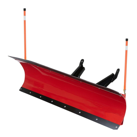
PARTS LIST
4 Flat Washer, 5/16”
4 Lock Washer, 10mm
1 Bolt, 3/8” dia – 1” long
4 Nut Nylock, 5/16”
6 Nut Nylock, 1/4”
1 Nut Nylock, 3/8”
4 Bolt, ¼”dia - 1 ¼” long
4 1/2” Spacers (AS38-14-32)
4 Bolt, 10mm – 1.25 thread – 25mm long
2 U-Bolt, 5/16” dia – 1 ½” wide (42021)
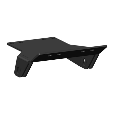
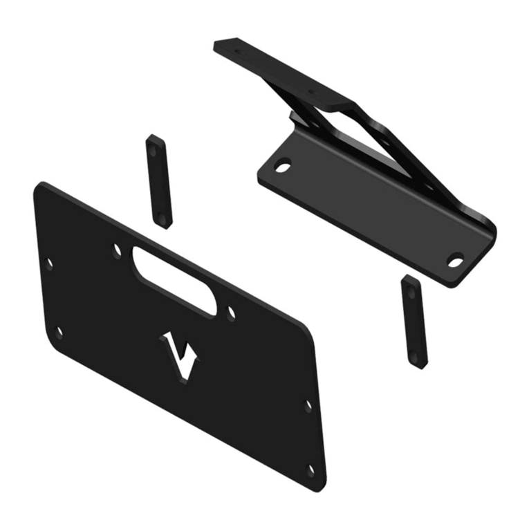
1 Mount Bracket Right
Mount Bracket Left
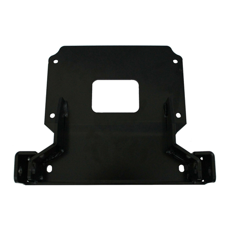
1 Mount Crossmember
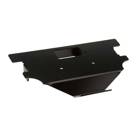
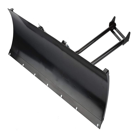
Plow Mount Assembly:
Remove the forward two bolts under the
bike on both sides that attach the foot
rest to the bike chassis. Take the
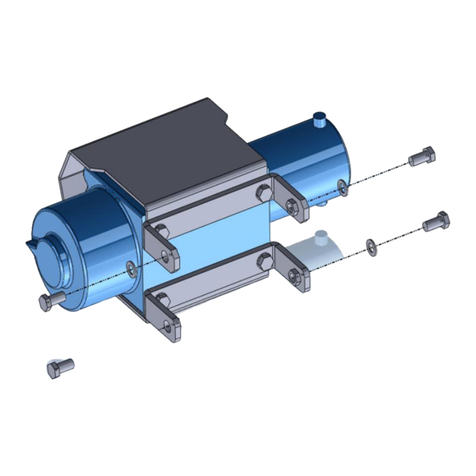
mounting brackets in the kit and place them
over the holes. Attach the mounting brackets
to the bike using four 10mm dia – 25mm
long bolts, and 10mm lock washers as
shown in figure 1. The lock washer should
be placed between the head of the bolt and
the flat washer. Do not tighten the bolts
all the way, you will do this later in the
installation. Installed properly, the
brackets will bend inward.
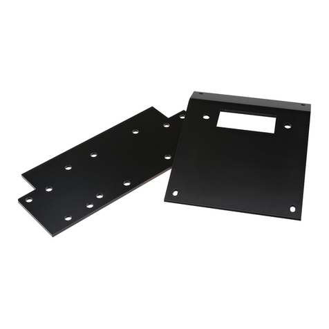
Place cross-member (73654) between the
two brackets. Insert the plow mounting
pins, this will help align the mount. The
top holes on the cross-member should be
toward the front of the bike. Using four ¼”
bolts and nuts, attach the cross-member the
brackets. Each bolt will go through a ½”
spacer positioned between the cross-member
and the brackets as shown in figure 2.
Tighten all bolts down snuggly.
Using the existing cross-member holes as
locators, drill through all four cross-member
holes with a 5/16” drill bit as shown in
figure 3. Drill only through the skid-plate
and nothing else on the bike. The plow
mounting pins can now be removed and
stored.
CAUTION
USE EXTREME CAUTION WHEN DRILLING
THROUGH THE SKIDPLATE. EVERY
EFFORT HAS BEEN MADE
TO ENSURE THAT THE HOLE POSITIONS
ON THE CROSSMEMBER WILL NOT ALLOW
THE DRILL BIT TO
CONTACT ANYTHING ELSE ON THE BIKE.
BUT VARIATIONS IN MANUFACTURING
AND INSTALLATION MAY
CHANGE THAT. KEEP AWAY ALL HANDS
AND LIMBS THAT MAY BE IN THE PATH OF
THE ROTATING BIT.
ONLY DRILL THROUGH THE SKIDPLATE
AND NOTHING ELSE ON THE BIKE. NOT
DOING SO MAY
SERIOUSLY DAMAGE/INJURE THE BIKE
AND OPERATOR.
Place the two 1-1/2” width U-bolts over the
chassis tubing, through the skid-plate, and
through the cross-member as shown in
figure 4.
Drill more material off the
skid-plate if necessary. Now attach the four
5/16” nuts and flat washers to the U-bolts
and tighten snuggly. Now go back and
tighten all four bolts on the mounting
brackets as shown in figure 1.
