Introduction
This compact DC - DC Isolated 4 step Booster charger uses the
latest switch-mode technology and is designed to meet all
modern automobile applications.
Galvanic isolated means you can connect to any load without
worrying about interference from the input to the output. The 4
step Booster Charger is designed to charge Lead-acid batteries
to its best status, thanks to the first step ( Time controlled charge).
This helps activate the battery status and wake up a weak or flat
battery to a suitable recharging level. This improves the battery
life and in turn helps to save the environment.
Since the DC supply from a vehicle’s generator is often unstable
and this will shorten the life of an electronic device. This DC-DC
isolated booster charger can be used as a constant power supply
to run accessories that require a stable and clean DC voltage.
For example: LCD TV, Digital Hi-Fi system, Wireless telephone
systems, refrigeration systems, LED lighting, games, mobile
computer and more....
The booster charger is designed with overload and short circuit
protection. It will automatically switch off the unit and re-start if
the overload or short circuit problem is corrected.
The cooling fan is thermal controlled. It will switch on and off
automatically to control the internal temperature of the unit.
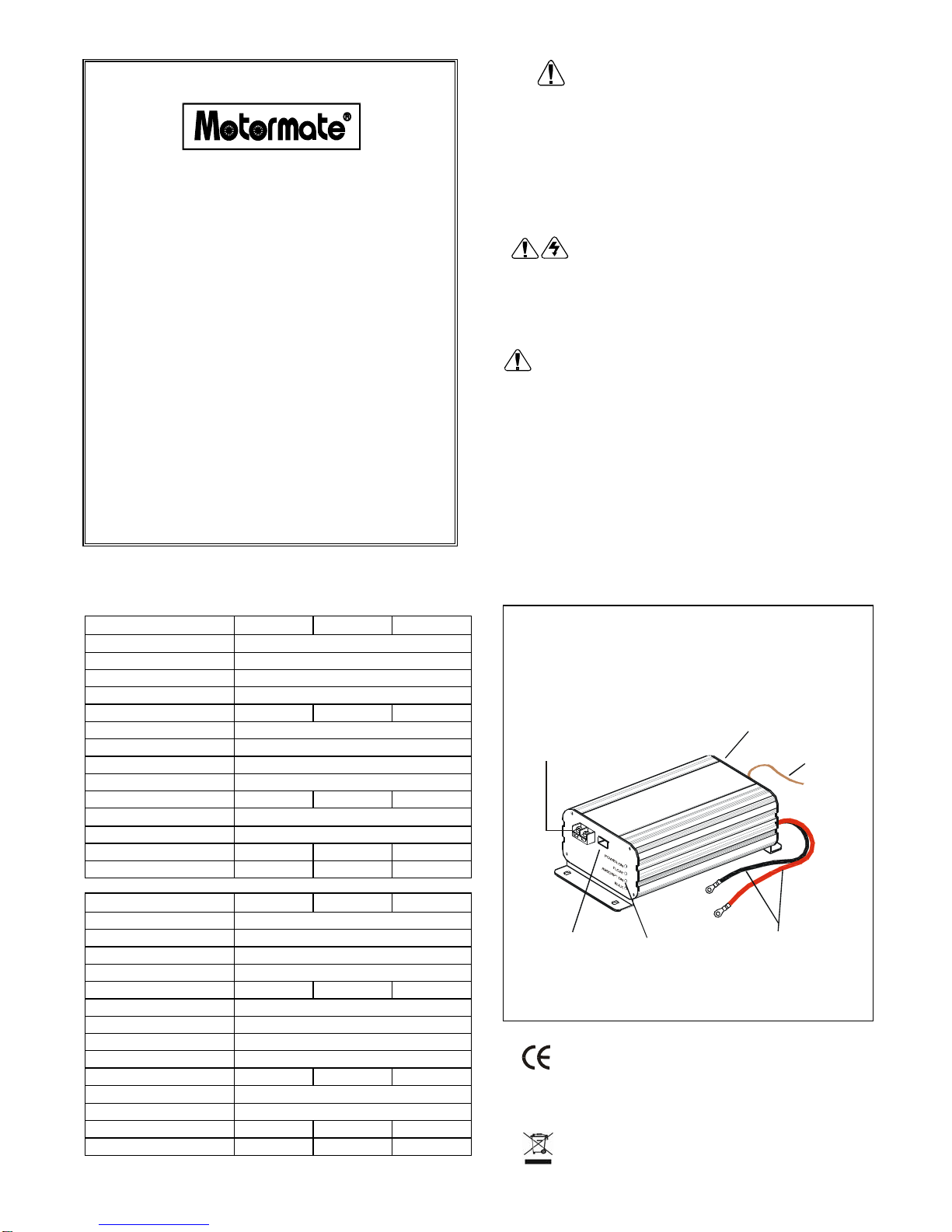
Remote on/off controls
The external lead wire on the rear panel is used for remote
switching with on-board voltage (e.g. ignition from the vehicle
engine or external switch). Note: The device power on/off switch
must be switched off after the external lead wire is connected.
CAUTION!
To prevent malfunction of the device, keep the external lead wire
insulated if it is not in use.
Instruction and normal responses
Operation as booster charger
Connect the input cable to the DC source. Turn On the Power
switch, the “POWER ON” LED lights up. This indicates the device
is ready for charging. The “BULK” LED lights up. This means the
battery charger is beginning at the 1st stage of charging.
According to the battery type, adjust the charge setting dip switch
to get the optimum charge.
Connect battery to the DC output terminal. The smart booster
charger will perform the four stage charge automatically.
The 1st stage is to ensure battery is
always charged at the maximum
charging condition. This is to boost
up the charging cycle and particularly
wake up a weak battery to absorb
energy.
In about 30 mins, the charger will
switch to 2nd stage, the “BULK” LED
remains ON, the battery is charged at
the maximum charging voltage. The
voltage level can be adjusted by the
switch No. 1,2 and 3.
At the 3rd stage, the charger will switch to “ABSORPTION” mode,
the red LED goes out and the yellow LED lights up. The device is
delivering maximum current to the battery.
At the 4th stage, the battery has been charged to about 85% of its
rated capacity. The “ABSORPTION” LED goes out and the
“FLOAT” LED lights up. Battery is now under “FLOAT” constant
charging. The charging voltage can be adjusted by the switch No.
4 and 5.
Operation as power supply
The device can be used as a Power Supply. Set the switch No. 6
to ON position. The device now operates as a power supply unit.
The bulk and absorption LED goes out. Switch No. 1,2 and 3 are
now disabled. The POWER ON and FLOAT LED light up. The
output voltage can be adjusted by the switch No. 4 and No.5.
CAUTION!
1. Do not use the device near flammable materials or in any
location that may accumulate flammable fumes or gasses.
2. Hot surface when operating, especially at full load condition.
3. Make sure the polarity is correct
4. Do not locate the device on the top of the battery. Especially
Flooded, Wet type battery. It may generate gas vapor while
charging.
5. Do not charge non-rechargeable batteries.
6. Use the appliance only in the described manner.
7. Do not expose the device to a heat source, such as direct
sunlight or heating.
8. Store the device in a dry and cool place
Output Voltage Setting Table
SWNo. Battery Selector Float Voltage Power Supply
1 ON OFF OFF
2 *ONOFF
3 **ON
4 ON OFF OFF ON OFF OFF
5 OFF ON OFF OFF ON OFF
6 OFF OFF OFF OFF OFF OFF ON ON ON
12V
Output 14.8 14.6 14.2 13.8 13.5 13.2 13.8 13.5 13.2
24V
Output 29.6 29.2 28.4 27.6 27.0 26.4 27.6 27.0 26.4
Note: Dip-SW No. 1, 2 and 3 are switched off automatically (regardless it is on/off), when Dip-SW
No. 6 is switched on.
Float Volt Bulk /Absorption Volt
Battery
Type Dip Switch Setting 12V 24V 12V 24V
SLA /GEL SW 3 ON, SW 1,2,4,5,6 OFF 13.2V 26.4V 14.2V 28.4V
AGM SW 2,5 ON, SW 1,3,4,6 OFF 13.5V 27.0V 14.6V 29.2V
FLOODED SW 1,4 ON, SW 2,3,5,6 OFF 13.8V 27.6V 14.8V 29.6V
Safety Operation!
A. If cables have to be fed through walls with sharp edges,
always use tubes or ducts to prevent damage.
B. Do not pull on the cable, fasten the device and cable securely.
Lay the cable so that it cannot be tripped over..
C. Use the device only in the described manner.
D. Children should be supervised to ensure that they do not play
with the device.
E. Do not allow water to drip or splash on the device.
F. Make sure the air inlets and outlets of the device are not
covered.
G. Operate the device only if you are certain that the housing
and the connection cables are undamaged.