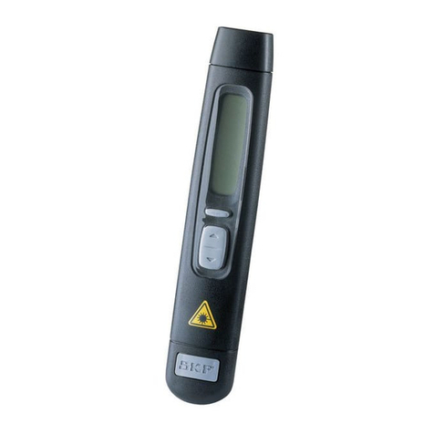
SKF TMSP 1 User manual

Instructions for use
Mode d’emploi
Bedienungsanleitung
Instrucciones de uso
Manuale d’istruzioni
Instruções de uso
使用说明书
Инструкция по эксплуатации
SKF TMSP 1


English 2
Français 12
Deutsch 22
Español 32
Italiano 42
Português 52
中文 62
Русский 72

2SKF TMSP 1
Table of contents
EC Declaration of conformity ...........................................................3
Safety recommendations .................................................................3
1. Introduction ..............................................................................4
1.1 Intended use .....................................................................................4
1.2 Principle of operation.......................................................................4
1.3 Distinguishing features ....................................................................4
2. Description ...............................................................................5
2.1 General description ..........................................................................5
2.2 Display ..............................................................................................6
3. Operation .................................................................................6
3.1 Measurement ....................................................................................8
3.2 Auto Power Off .................................................................................8
3.3 Calibration..........................................................................................9
4. Technical data ..........................................................................9
5. Remarks ................................................................................11
5.1 Operating precautions ...................................................................11
5.2 Environment conditions ...............................................................11
5.3 Maintenance and cleaning ...........................................................11
Original instructions

3
SKF TMSP 1
Safety recommendations
• Do not expose the equipment to rough handling or heavy impacts.
• Always read and follow the operating instructions.
• Opening the housing of the instrument may result in hazardous
mishandling and voids warranty.
• The equipment should not be used in areas where there is a risk
for explosion.
• Do not expose the equipment to high humidity or direct contact
with water.
• All repair work should be performed by an SKF repair shop.
EC Declaration of conformity
We,
SKF Maintenance Products
Kelvinbaan 16
3439 MT Nieuwegein
The Netherlands
herewith declare that the following product:
SKF Sound Pressure Meter
TMSP 1
is designed and manufactured in accordance with the
EMC DIRECTIVE 2004/108/EC Standards applied IEC651 type 2,
ANSI S1.4 Type2 for Sound Level Meters.
EUROPEAN ROHS DIRECTIVE 2011/65/EU
Nieuwegein, The Netherlands,
October 2013
Sébastien David
Manager Product Development and Quality

4SKF TMSP 1
1. Introduction
The SKF Sound Pressure Meter TMSP 1 is designed to measure sound
level in any working area, outside or inside any building. Common noise
pollution can therefore be quantified, almost any noise, but especially for
industrial and environmental noise.
1.1 Intended use
In many countries, the use of A-weighting is mandated to be used for
the protection of workers against noise induced deafness. Moreover,
C-weighting is used in the measurement of peak values of a noise in
some legislation.
1.2 Principle of operation
The principle of operation of the TMSP 1 can be compared to a
microphone, with measurement capabilities. The AC signal from the
microphone is converted to DC by a root-mean-square (RMS) circuit and
thus it must have a time-constant of integration (time-weighting). Two
time-weightings are available on TMSP 1: Slow (1 s) and Fast (125 ms).
1.3 Distinguishing features
TMSP 1 includes a back light LCD, a fast analogue bar and an auto range
function.

5
SKF TMSP 1
2. Description
The SKF Sound Pressure Meter TMSP 1 is made of one handheld
component with controls and sensor and a foam windscreen for outside use.
2.1 General description
OPEN
MANUAL FOR SAFETY
NEDA 1604 6F22 006P
PLEASE READ
9V BATTERY
IEC 651 TYPE II
80dB
100dB
130dB
Lo = 30
Med= 50
Hi = 80
LEVEL
FASTMAX
A/C
2
1
3
4
5
7
6
8
9
DC 9V CAL
OUTPUT -
RS 232
1 Windscreen
2 Display
3 Power & Backlight button
4 MAX/MIN hold button
5 Level range control switch
6 Frequency weighting select button
7 Time weighting select button
8 Microphone
9 CAL potentiometer
10 RS-232 Interface
11 Signal Output Terminal
12 External DC 9V power supply terminal
13 Tripod Mounting Screw
14 Battery Cover

6SKF TMSP 1
2.2 Display
Symbol Function
LCD 4 digits
MAX Maximum indication
MIN Minimum indication
Over range
Under range
FAST Fast response
SLOW Slow response
dBA A-Weighting
dBC C-Weighting
Range Indicate
Low Battery
Under range 20 dB
AUTO Auto Level range selective
3. Operation
• Windscreen (1)
If you operate at wind speed over 10 ms, put protective accessories
over the microphone.
• Power & Backlight button (3)
The key turns the sound level meter ON or OFF and backlight ON & OFF.
Press it once to turn on the sound level meter.
Press it again for moment to turn ON or OFF backlight.
Press and hold this button 3 second to turn OFF the power.
• MAX / MIN hold button (4)
Press button to enter the maximum and minimum recording
mode. Select the proper Level range before using MAX/MIN to
ensure that reading value will not exceed the measurement range.
Press once to select MAX value. Press again to select MIN value, and
press again to select current value with “ MAX/MIN “ annunciator
blinking. Press and hold down button for 2 seconds to exit
the MAX/MIN mode.

7
SKF TMSP 1
Note: If sound level range or A-C weighting is changed, the
MAX/MIN mode will clear.
• Level range control switch (5)
Each time the UP button is pressed. The level range increments
from “Lo” Level to “Hi“ Level range and to “Auto” Level range.
Each time the DOWN button is pressed. The range decreases from
“Auto” Level range to “Hi” Level and to “Lo“ Level range.
• Frequency Weighting select button (6)
A : A - Weighting; for general sound level measurements.
C : C - Weighting; for checking the low-frequency content of noise.
(If the C-Weighted level is much higher than the A-weighted level,
then there is a large amount of low-frequency noise)
• Time weighting select button (7)
FAST : for normal measurements
SLOW : for checking average level of fluctuating noise.
• Microphone (8)
1/2 inch Electret Condenser microphone.
• CAL potentiometer (9)
Calibration control. For level calibration
adjustment.
The RS-232 signal output is a 9 600 bps
N 8 1 serial interface. (10).
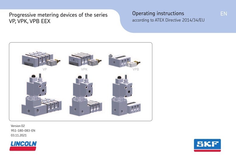
• Signal output terminal (11)
AC: 1 Vrms Corresponding to each range step. Output impedance
approx. 100Ω. Output signal by standard 3,5 mm coaxial socket
signal on pin.
Note: At “Auto” level range, output signal is Auto select on “Lo”
or “Med” or “Hi” level range.
DC: Output : 10mV/dB.
Output impedance approx. 1KΩ
Output signal by standard 3,5 mm
coaxial socket signal on middle.
• External DC 9V power supply terminal (12)
For connection with AC adapter.
DC Signal
AC Signal
Ground
8SKF TMSP 1
3.1 Measurement
• Open battery cover and install the battery in the battery compartment.
Observe the polarity when installing.
• Turn power on and select the desired response Time and Weighting.
If the sound source consists of short bursts or only catching sound
peaks, set response to FAST. To measure average sound level, use
the SLOW setting.
• Select A-weighting for general noise sound level and C-weighting for
measuring sound level of acoustic material.
• Select desired Level.
• Hold the instrument comfortably in hand or fix on tripod and point
the microphone at the suspected noise source, the sound pressure
level will be displayed.
• When MAX/MIN (maximum, minimum hold) mode is chosen, the
instrument captures and holds the maximum and minimum noise
level for a long period using any of the time weightings and ranges.
• Press the MAX/MIN button 2 seconds to clear the MAX/MIN reading.
“MAX/MIN” symbol disappears.
• Turn OFF the instrument and remove battery when not in use.
3.2 Auto Power Off
By default, when the meter is powered on, it is under auto power
off mode. The meter will power itself off after 30 minutes if no key
operation and no RS232 communication and no recording combination
at power on can disable auto power off.
One may press and hold “FAST/SLOW” button and then power on the
meter and the
will not show up to indicate that auto power off
is disabled.

9
SKF TMSP 1
3.3 Calibration
Using a standard Acoustic Calibrator (94dB, 1KHz Sine wave)
MIN
MAX
C
A
FAST
SLOW
IEC 651 TYPE II
50
Med= 100 dB
Hi = 80 130 dB
LEVEL
Lo = 30 80 dB
CAL
IEC 60942 Class 2
ANSI S1.40 - 1984
OFF
94dB
114dB
• Make the following switch settings:
- Display: dBA.
- Time weighting: FAST.
- Measurement mode: MAX/MIN Mode function disable.
- Level range: 50 to 100 dB
• Insert the microphone housing carefully into the insertion hole of
the calibrator.
• Turn on the switch of calibrator and adjust the CAL potentiometer
of the unit. The level display will indicate the desired level. All
products are well calibrated before shipment. Recommended
Recalibration cycle: 1 year.
4. Technical data
Standard applied IEC651 Type2, ANSI S1.4 Type2
Frequency range 31,5 Hz ~ 8 KHz
Measuring level
range 30 ~ 130 dB
Frequency weighting A/C
Microphone 1/2 inch electret condenser microphone
Display LCD
Digital display 4 digits
Resolution: 0,1 dB
Display update 0,5 s.
Analog display 50 segment bargraph
Resolution 1 dB
Display update 100 ms
Time weighting FAST (125 ms), SLOW (1 s)
Level ranges Lo: 30 – 80 dB / Med: 50 – 100 dB
Hi: 80 – 130 dB / Auto: 30 – 130 dB
Accuracy ± 1,5 dB
(under reference conditions @ 94 dB, 1 KHz)
Dynamic range 50 dB
Screwdriver
Acoustic calibrator

10 SKF TMSP 1
Alarm function “OVER” is when input is more than upper
limit of range
“UNDER” is when input is less than lower
limit of range
MAX/MIN hold Hold readings the Maximum and Minimum Value
AC output 1 Vrms at FS (full scale)
Output impedance: Approx. 100 Ω
FS: means the upper limit of each level range
DC output 10mV / dB, output impedance approx. 1 KΩ
Power supply One 9 V battery, 006P or IEC 6F22 or
NEDA 1604
Power life About 50 hrs (alkaline battery)
AC adapter Voltage 9 VDC ( 8 - 10 VDC Max )
Supply current: > 30 mADC
Casing positive
Internal diameter
1,35 mm
Socket: pin ground
External diameter
3,5 mm
Electromagnetic
compatibility RF field = 3 V/m
Total accuracy = specified accuracy + 0,5 dB
Operation
temperature 0 to 40 ºC (32 to 104 ºF)
Operation humidity 10 to 90% RH
Storage temperature -10 to 60 ºC (14 to 140 ºF)
Storage humidity 10 to 75% RH
Dimensions 275 (L) × 64 (W) × 30 (H) mm
(10.8 (L) × 2.5 (W) × 1.2 (H) inch)
Weight 285 g (including battery)
Accessories 9V battery, carrying case, screwdriver,
Instruction for Use
Windscreen, 3,5 ψ plug
Size and Weight
Carrying Case
dimensions
530 ™ 85 ™ 180 mm
(20.9 ™ 3.4 ™ 7.0 in.)
Total weight
(incl. case)
1,1 kg
(2.4 lb)
Spare part
TDTC 1/X General toolcase without inlay, size X

11
SKF TMSP 1
5. Remarks
• Battery Loading:
Remove the battery cover on the back and put in one 9V Battery.
• Battery Replacement:
When the battery voltage drops below the operating voltage, this
symbol will appear
. Replace 9 Volt battery.
• AC Adapter Connection:
When the AC adapter is used, insert the plugs of the adapter into the
DC9V connector on the side panel.
5.1 Operating precautions
• Wind blowing across the microphone would bring additional
extraneous noise. When using the instrument in the presence
of wind, it is a must to mount the windscreen to not pick up
undesirable signals.
• Calibrate the instrument before operation if the instrument was not
in use for a long time or operated in bad environment.
• Do not store or operate the instrument at high temperature and high
humidity environment.
• Keep microphone dry and avoid severe vibration.
• When not in use: Take out the battery and keep the instrument in
low humidity environment.
5.2 Environment conditions
• Altitude up to 2 000 meters.
• Relatively humidity 90% max.
• Operation Ambient 0 ~ 40 ºC.
5.3 Maintenance and cleaning
• Repairs or servicing not covered in this manual should only be
performed by qualified personnel.
• Periodically wipe the case with a dry cloth.
• Do not use abrasives or solvents on this instrument.

12 SKF TMSP 1
Table des matières
Déclaration de conformité CE ........................................................13
Recommandations de sécurité .......................................................13
1. Introduction ............................................................................14
1.1 Utilisation prévue ...........................................................................14
1.2 Principe de fonctionnement ..........................................................14
1.3 Caractéristiques distinctives .........................................................14
2. Description .............................................................................15
2.1 Description générale ......................................................................15
2.2 Affichage .........................................................................................16
3. Fonctionnement ......................................................................16
3.1 Mesure ............................................................................................18
3.2 Fonction d’arrêt automatique .......................................................18
3.3 Étalonnage ......................................................................................18
4. Caractéristiques techniques ....................................................19
5. Remarques .............................................................................21
5.1 Précautions d’utilisation ................................................................21
5.2 Conditions d’environnement ........................................................21
5.3 Entretien et nettoyage ...................................................................21
Traduction extraite du mode d’emploi d’origine

13
SKF TMSP 1
Recommandations de sécurité
• Évitez de manipuler brutalement ou de faire tomber l’appareil.
• Lisez et respectez toujours les instructions d’utilisation.
• L’ouverture du boîtier de l’instrument peut entraîner une
manipulation dangereuse et l’annulation de la garantie.
• L’appareil ne doit pas être utilisé dans des endroits présentant
un danger d’explosion.
• N’exposez pas l’appareil à une humidité élevée et ne le mettez
pas au contact direct de l’eau.
•
Toute réparation doit être effectuée par un atelier de réparation SKF.
Déclaration de conformité CE
Nous,
SKF Maintenance Products
Kelvinbaan 16
3439 MT Nieuwegein
Pays-Bas
déclarons que le produit suivant:
Le dispositif SKF de mesure de pression acoustique
TMSP 1
a été conçu et fabriqué en conformité avec les normes de
la DIRECTIVE CEM 2004/108/CE en application de IEC651
type 2, ANSI S1.4 Type2 pour les dispositifs de mesure de
pression acoustique.
EUROPEAN ROHS DIRECTIVE 2011/65/EU
Nieuwegein, Pays-Bas,
Le 1 octobre 2013
Sébastien David
Responsable Développement de Produits et Responsable Qualité

14 SKF TMSP 1
1. Introduction
Le dispositif SKF de mesure de pression acoustique TMSP 1 est conçu
pour mesurer la pression acoustique dans toute zone de travail, à
l’intérieur et à l’extérieur de tout bâtiment. La pollution sonore commune
peut donc être quantifiée, presque tout bruit, mais spécialement les
bruits industriels et environnementaux.
1.1 Utilisation prévue
Dans de nombreux pays, l’emploi de la pondération A est obligatoire pour
la protection des travailleurs contre la surdité provoquée par le bruit.
Par surcroît, la pondération C est employée afin de mesurer les valeurs
de crête des bruits, dans le cadre de certaines législations.
1.2 Principe de fonctionnement
Le principe de fonctionnement du TMSP 1 est comparable à celui d’un
microphone dotée de capacités de mesure. Le signal CA du microphone
est converti en CC par un circuit de valeur quadratique
(RMS – Root mean square) et doit donc avoir une constante
temporelle d’intégration (pondération temps). Le TMSP 1 propose deux
pondérations temporelles : Lente (1 s) et Rapide (125 ms).
1.3 Caractéristiques distinctives
Le TMSP 1 inclut un rétroéclairage LCD, une barre analogique rapide et
une fonction de plage automatique.

15
SKF TMSP 1
2. Description
Le dispositif SKF de mesure de pression acoustique TMSP 1 comporte
un composant portable avec commandes et capteurs et un écran anti-
vent en mousse pour usage extérieur.
2.1 Description générale
OPEN
MANUAL FOR SAFETY
NEDA 1604 6F22 006P
PLEASE READ
9V BATTERY
IEC 651 TYPE II
80dB
100dB
130dB
Lo = 30
Med= 50
Hi = 80
LEVEL
FASTMAX
A/C
2
1
3
4
5
7
6
8
9
DC 9V CAL
OUTPUT -
RS 232
1 Écran anti-vent
2 Affichage
3 Bouton d’alimentation et rétroéclairage
4 Bouton de maintien MAX/MIN
5 Interrupteur de contrôle de plage de niveau
6 Bouton de sélection de pondération de fréquence
7 Bouton de sélection de pondération temporelle
8 Microphone
9 Potentiomètre CAL
10 Interface RS-232
11 Borne de sortie de signal
12 Borne d’alimentation électrique CC 9V externe
13 Vis de montage de trépied
14 Cache de batterie

16 SKF TMSP 1
2.2 Affichage
Symbole Fonction
LCD 4 caractères
MAX Indication Maximum
MIN Indication Minimum
Plage supérieure
Plage inférieure
FAST Réponse rapide
SLOW Réponse lente
dBA Pondération A
dBC Pondération C
Indication de plage
Pile faible
Plage inférieure 20 dB
AUTO Sélection de plage Niveau auto
3. Fonctionnement
• Écran anti-vent (1)
Si vous travaillez avec un vent dépassant les 10 ms, positionnez les
accessoires de protection sur le microphone.
• Bouton d’alimentation et rétroéclairage (3)
La clé met en marche/arrêt le dispositif de mesure de pression
acoustique et le rétroéclairage. Une pression met le dispositif de
mesure de pression acoustique en marche.
Une nouvelle pression prolongée active/désactive le rétroéclairage.
Une pression de plus de 3 secondes sur ce bouton coupe
l’alimentation.
• Bouton de maintien MAX / MIN (4)
Une pression sur le bouton permet d’accéder au mode
d’enregistrement maximum et minimum. Sélectionnez la plage de
niveau appropriée avant d’utiliser MAX/MIN pour garantir que la
valeur de lecture ne dépasse pas la plage de mesure. Une pression

17
SKF TMSP 1
sélectionne la valeur MAX. Une nouvelle pression sélectionne la
valeur MIN et une autre pression sélectionne la valeur active avec
l’annonce « MAX/MIN » clignotante. Une pression sans relâcher le
bouton pendant 2 secondes sélectionne la sortie du mode
MAX/MIN.
Note: en cas de changement de la plage de niveau acoustique ou de
la pondération A, le mode MAX/MIN s’annule.
• Interrupteur de contrôle de plage de niveau (5)
À chaque pression du bouton ‘HAUT’, la plage de niveau s’accroît du
niveau « Lo » au niveau « Hi » puis à la plage de niveau « Auto ».
À chaque pression du bouton ‘BAS’, la plage de niveau se réduit de
la plage de niveau « Auto » au niveau « Hi » puis au niveau « Lo ».
• Bouton de sélection de pondération de fréquence (6)
A : Pondération A – Pour les mesures de pression acoustique
générales.
C : Pondération C – Pour le contrôle des contenus sonores basses
fréquences
(Si le niveau pondéré C est très supérieur au niveau pondéré A, la
pression acoustique basse fréquence est très élevée)
• Bouton de sélection de pondération temporelle (7)
FAST : pour mesures normales
SLOW : pour contrôle de niveau moyen de bruit fluctuant.
• Microphone (8)
Microphone à électret 1/2 pouce.
• Potentiomètre CAL (9)
Commande d’étalonnage du réglage
d’étalonnage de niveau.
La sortie de signal RS-232 est une interface
série 9 600 bps N 8 1. (10).
• Borne de sortie de signal (11)
CA: 1 Vrms correspondant à chaque niveau de plage. Impédance en
sortie 100 Ω. Signal de sortie par signal de douille coaxial
3,5 mm standard sur broche.
Note: pour la plage de niveau
« Auto », le signal de sortie
est automatiquement
sélectionné sur la plage de
niveau « Lo », « Med » ou « Hi ».
CC: Sortie : 10 mV/dB
Impédance en sortie environ 1 KΩ
Signal de sortie par signal de douille coaxial 3,5 mm
standard sur milieu.
• Borne d’alimentation électrique CC 9V externe (12)
Pour connexion avec adaptateur CA.
DC Signal
AC Signal
Ground
18 SKF TMSP 1
3.1 Mesure
• Ouvrez le cache de la pile et installez-la dans son logement.
Respectez la polarité d’installation.
• Mettez en marche et sélectionnez le délai de réponse et la
pondération désirés. Pour une source acoustique composée de bruits
brefs ou si vous captez uniquement les crêtes sonores, réglez la
réponse sur FAST. Pour mesurer une pression acoustique moyenne,
réglez sur SLOW.
• Sélectionnez la pondération A pour une pression acoustique générale
et la pondération C pour mesurer la pression sonore d’un matériel
acoustique.
• Sélectionnez le niveau souhaité.
• Tenez l’instrument confortablement dans une main ou fixez-le sur le
trépied et pointez le microphone sur la source de bruit suspectée. Le
niveau de pression acoustique s’affiche.
• En mode MAX/MIN (maintien maximum, minimum), l’instrument
capture et maintient les niveaux de pression acoustique maximum et
minimum sur une période prolongée pour toutes les pondérations et
plages.
• Une pression sur le bouton MAX/MIN pendant 2 secondes efface la
lecture MAX/MIN. Le symbole « MAX/MIN » disparaît.
• Arrêtez l’instrument et retirez la pile s’il n’est plus utilisé.
3.2 Fonction d’arrêt automatique
Par défaut, lorsque le dispositif est en marche, il est réglé en mode
d’arrêt automatique. En l’absence de pression sur un bouton et de
communication RS232, le dispositif s’arrête automatiquement après
30 minutes. Aucune combinaison d’enregistrement lors de la mise en
marche ne peut désactiver l’arrêt automatique.
Il est possible d’appuyer sur le bouton « FAST/SLOW » puis de mettre le
dispositif en marche et le
ne s’affiche pas pour indiquer que l’arrêt
automatique est désactivé.
3.3 Étalonnage
Utilisation d’un étalonneur acoustique standard (94 dB, sinusoïde 1 KHz).
MIN
MAX
C
A
FAST
SLOW
IEC 651 TYPE II
50
Med= 100 dB
Hi = 80 130 dB
LEVEL
Lo = 30 80 dB
CAL
IEC 60942 Class 2
ANSI S1.40 - 1984
OFF
94dB
114dB
• Réglez les interrupteurs comme suit:
- Écran: dBA
- Pondération temporelle: FAST
- Mode de mesure: fonctionnement en mode MAX/MIN désactivé
- Plage de niveau: 50 à 100 dB.
• Insérez le boîtier du microphone avec soin dans l’orifice d’insertion
de l’étalonneur.
Tournevis
Étalonneur acoustique
Table of contents
Languages:
Other SKF Measuring Instrument manuals

SKF
SKF THGD 100 User manual

SKF
SKF LAGM 1000E User manual

SKF
SKF On-line System WVT User manual

SKF
SKF Lincoln SSV EEX Series User manual

SKF
SKF SMD 1B User manual

SKF
SKF TMEH 1 User manual

SKF
SKF 800030 Product manual

SKF
SKF Multilog IMx-S Series User manual

SKF
SKF Baker AWA-IV Series User manual

SKF
SKF IMx-Rail User manual