MoVeS OXYCYCLE 1 User manual

The specications of this product may vary from this photo, subject to change without notice.
English .................................................................... 2
Nederlands ......................................................... 8
Deutsch ............................................................... 14
Français ............................................................... 20
Espagnol ............................................................. 26
Svenska ............................................................... 32
Suomi ................................................................... 38
AROv1

2
Read all instructions carefully before operating. Retain this owner’s manual and keep all
original transaction receipts for future reference.
• Consult your physician before beginning your exercise program.
• If you experience any irregular physical conditions such as dizziness, severe muscle or
joint pain or pain in the chest, stop exercising and consult your physician immediately.
• Keep children and pets away from the machine while in use.
• Do not wear loose clothing while exercising.
• Keep a minimum safety clearance during operation.
• Do not operate the exercise equipment if it is damaged.
• Set up Pedal Exerciser as directed in Assembly Instructions and place unit on a at, stable,
non-slip surface.
• Perform 3 to 5 minutes of warm-up and stretching before beginning your exercise.
• Each exercise should be performed in a controlled manner. Always start exercising slowly.
• Never exercise to exhaustion.
• Do not stand on the Pedal Exerciser.
• The Pedal Exerciser is designed as a home use exercise device.
• Users must have full control of their muscles to operate this unit. It may not be suitable for
people who are quadriplegic or paraplegic. Please consult your doctor or physician.
• Exercise equipment is to be regularly inspected for maintenance for loose or broken
parts.
• Have the unit serviced by a qualied service technician. Do not attempt to service the
unit yourself.
Storage Precautions:
Do not store the unit in any place where it will be subject to high or low temperatures. Do not
expose to direct sunlight for extended periods of time. Do not store the unit in a humid or
dusty area.
Safety Precautions ........................................................ 2
Overview Drawing ........................................................ 3
Parts List ........................................................................... 4
Assembly Instructions ................................................. 5
Operating the Controller ........................................... 6
Operating the Resistance Control Knob ............... 6
Workout .......................................................................... 7
Safety Precautions
Table of Contents

3
4
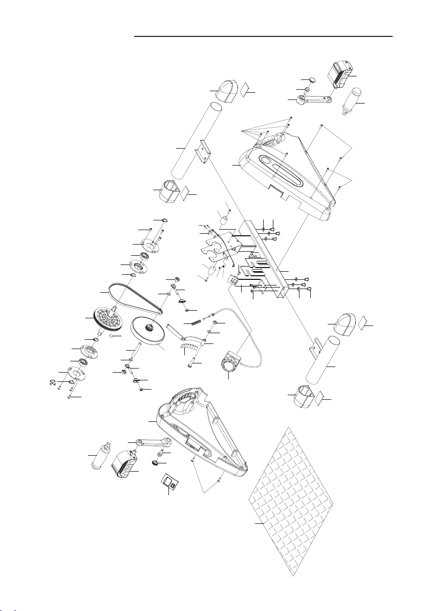
EXPLODED VIEW
Overview Drawing
45 41
16
37
22
44
2
11
40
32
38
3
19
25
1
9
23
26
21
13
35
29
30
31
4
39
15
17
17
18
18
19
20
21
24
24
24
26
27
28
32
33
34
36
39
7
8
10
12
14
33
6
43
42
46
12
13
20
20
24
34
10
8
25
27
28
34
10
34
10
5
47
35
48
48
50
49

4
Parts List
6
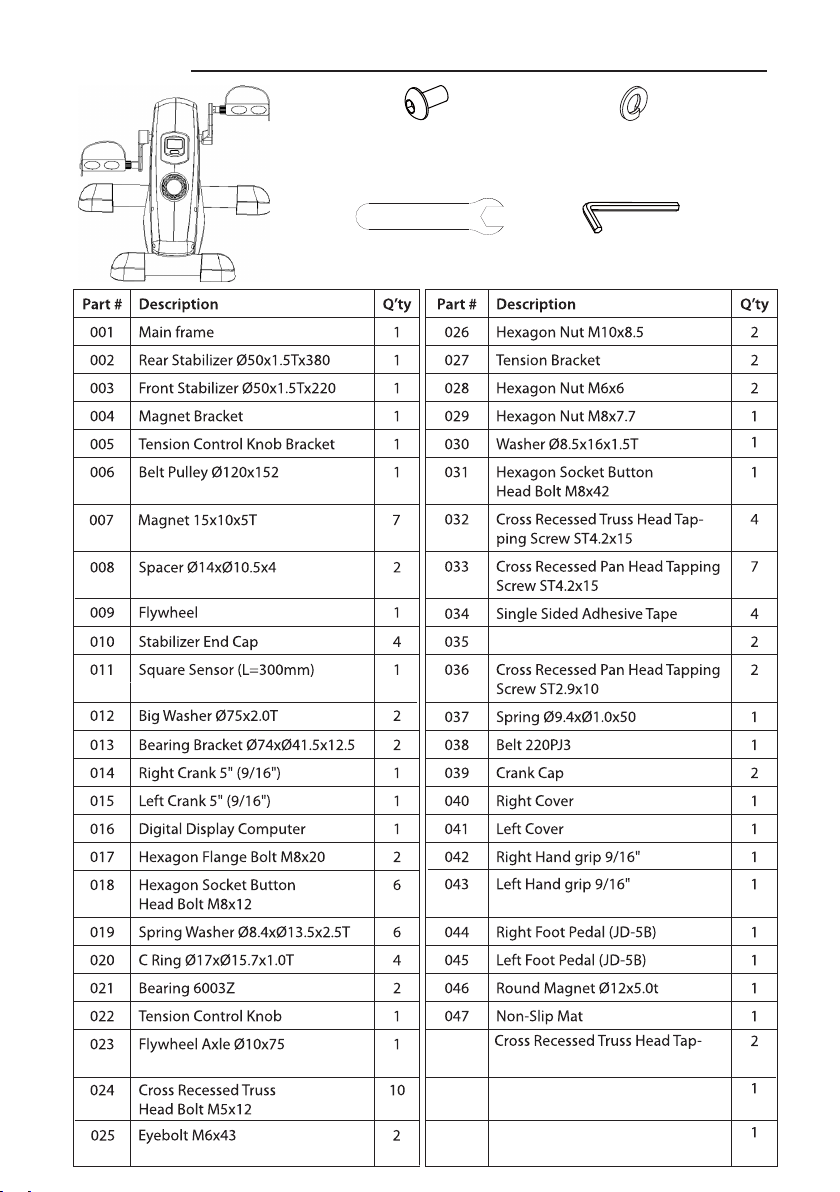
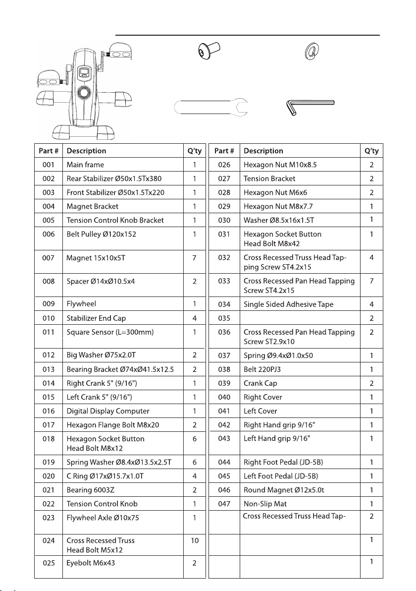
PARTS LIST
No. Description Qty No. Description Qty
039 Crank Cap 2 044 Right Foot Pedal
(JD-5B) 1
040 Right Cover 1 045 Left Foot Pedal (JD-5B) 1
041 Left Cover 1 046 Round Magnet Ø12x5.0t 1
042 Right Hand grip 9/16" 1 047 Non-Slip Mat 1
043 Left Hand grip 9/16" 1
HARDWARE LIST & TOOLS
Part # Description Q’ty Part # Description Q’ty
001 Main frame 1
025 Eyebolt M6x43 2
002 Rear Stabilizer Ø50x1.5Tx380 1
026 Hexagon Nut M10x8.5 2
003 Front Stabilizer Ø50x1.5Tx220 1
027 Tension Bracket 2
004 Magnet Bracket 1
028 Hexagon Nut M6x6 2
005 Tension Control Knob Bracket 1
029 Hexagon Nut M8x7.7 1
006 Belt Pulley Ø120x152 1
030 Washer Ø8.5x16x1.5T
031 Hexagon Socket Button
Head Bolt M8x42
1
032 Cross Recessed Truss Head Tap-
ping Screw ST4.2x15
4
009 Flywheel 1
033 Cross Recessed Pan Head Tapping
Screw ST4.2x15
7
010 Stabilizer End Cap 4
034 Single Sided Adhesive Tape 4
011 Square Sensor (L=300mm) 1
035 2
012 Big Washer Ø75x2.0T 2
036 Cross Recessed Pan Head Tapping
Screw ST2.9x10
2
013 Bearing Bracket Ø74xØ41.5x12.5 2
037 Spring Ø9.4xØ1.0x50 1
014 Right Crank 5" (9/16") 1
038 Belt 220PJ3 1
015 Left Crank 5" (9/16") 1
039 Crank Cap 2
016 Digital Display Computer 1
040 Right Cover 1
017 Hexagon Flange Bolt M8x20 2
041 Left Cover 1
018 Hexagon Socket Button
Head Bolt M8x12
6
042 Right Hand grip 9/16" 1
019 Spring Washer Ø8.4xØ13.5x2.5T 6
043 Left Hand grip 9/16" 1
020 C Ring Ø17xØ15.7x1.0T 4
044 Right Foot Pedal (JD-5B) 1
021 Bearing 6003Z 2
045 Left Foot Pedal (JD-5B) 1
022 Tension Control Knob 1
046 Round Magnet Ø12x5.0t 1
023 Flywheel Axle Ø10x75 1
047 Non-Slip Mat 1
024 Cross Recessed Truss
Head Bolt M5x12
10
007 Magnet 15x10x5T 7
008 Spacer Ø14xØ10.5x4 2
048048
049049
005050
1
PVC Pad Ø18.5xØ17x9PVC Pad Ø18.5xØ17x9
2
1
1
Cross Recessed Truss Head Tap-
ping Screw ST4.2x20ping Screw ST4.2x20
Hexagon Nut MHexagon Nut M55xx44
Cross Cross Recessed Recessed Pan Pan Head Head
Bolt M5x1Bolt M5x155
Allen Wrench
1 PC
(18) Hexagon Socket
Button Head Bolt
6 PCS
(19) Spring Washer
6 PCS
Wrench
1 PC

5
1 2
34
5 6
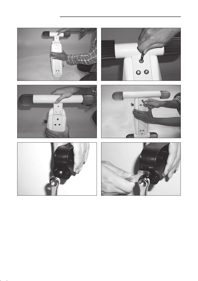
1. Hold the unit in an upright position.The controller side facing up. Insert the front stabilizer
(3) into the main frame (1).
2. Attach the front stabilizer (3) to the main frame (1) with three bolts (18) and three spring
washers (19).
3. Insert the rear stabilizer (2) into the main frame (1).
4. Attach the rear stabilizer (2) to the main frame (1) with three bolts (18) and three spring
washers (19).
5. Connect the left foot pedal (45) to the left crank (15) assembly. Thread it into the crank
assembly in a counter-clockwise direction with the tool provided. (See gures 5 and 6).
Connect the right foot pedal (44) to the right crank (14) assembly by threading it in a
clockwise direction. Note: The left/right pedals and left/right cranks are marked with
“L”and “R” (left and right)
Assembly Instructions
6
Operating the Digital Display Computer
Computer Button Functions
Push the button to turn on the display.
Push the button to select a function.
Push and hold the button for 3 seconds to reset
all functions except for the T.REPS function.
Computer Display Functions & Measuring Range
STOP The unit is stopped.
AUTO START Start motion or push button.
DISPLAY OFF After approximately 4 minutes without operation.
Battery Replacement
Remove the display by using a slotted
screwdriver.
Remove the battery with a slotted
screwdriver. Replace with a new
3V lithium button cell battery.
8-level resistance control knob
The resistance can be adjusted by turning the resistance control knob.
To increase the resistance, turn the resistance control knob in a clockwise
direction. To decrease the resistance, turn the resistance control knob in a
counterclockwise direction.
Operating the Resistance Control Knob
How to use your OxyCycle 1 Pedal Exerciser.
When using the OxyCycle 1, the proper way to exercise is to set the desired resistance by
turning the resistance control knob, and then pedaling to get the best results. Pedaling at
excessive speeds or applying excessive force will damage the product or may cause injury to
persons. Please start exercising at a slow pedaling speed.
9
OPERATING THE DIGITAL DISPLAY COMPUTER
COMPUTER BUTTON FUNCTIONS:
Push the button to turn on the display.
Push the button to select a function.
Push and hold the button for 3 seconds to reset all
functions to zero except for the TOTAL REPS function.
COMPUTER DISPLAY FUNCTIONS &
MEASURING RANGE:
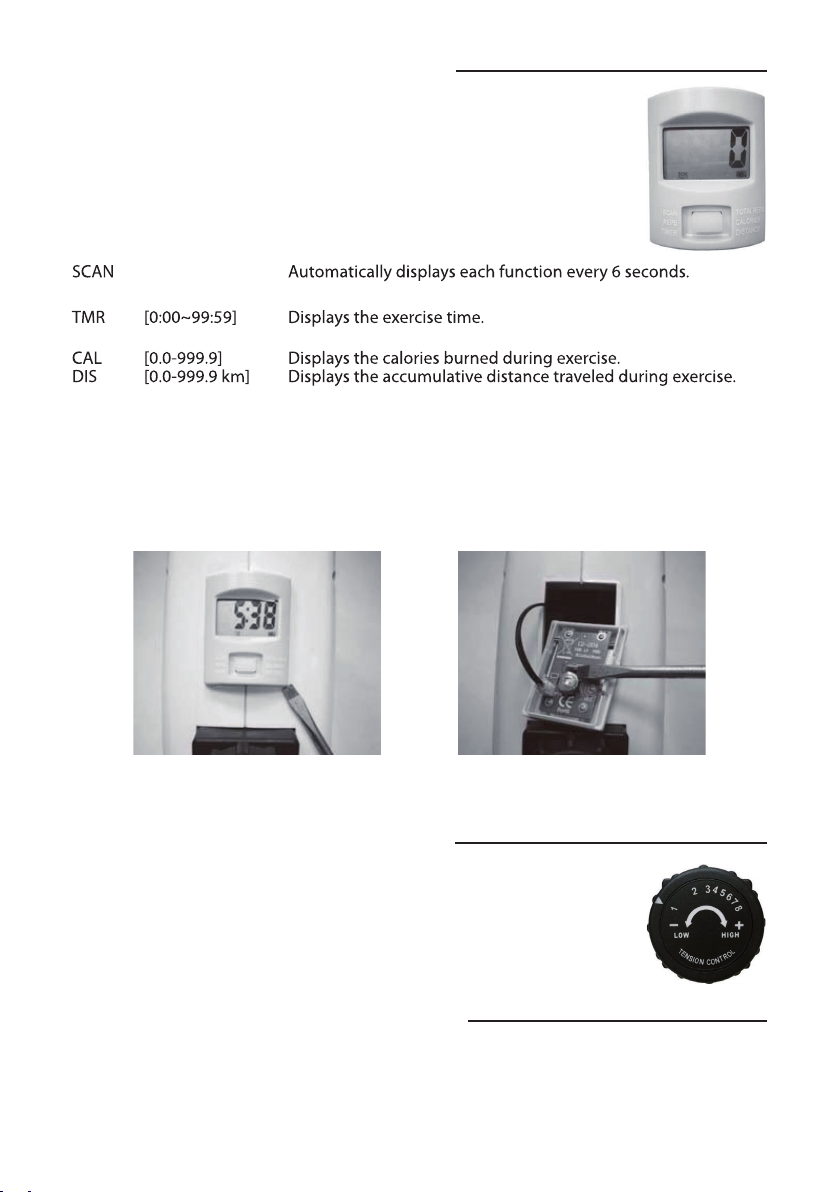
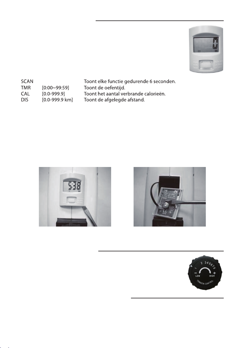
SCAN: Automatically displays each function every 6
seconds.
SCAN→→REP→→TMR→→T.REPS→→CAL→→KM
REP (0~9999): Displays the number of time of rotation.
TMR (0:00~99:59): Displays the exercise time.
T.REPS (0~9999): Displays the number of total rotation.
CAL (0.0~999.9): Displays the calories burned during exercise.
KM (0.0~199.9): Displays the current training speed in kilometers per hour.
STOP: The unit is stopped.
AUTO START: Start motion or push button.
AUTO DISPLAY SHUT OFF: After approximately 4 minutes without operation.
BATTERY REPLACEMENT:
Remove the battery
with a slotted
screwdriver.
Replace with a new
Button Cell Battery.
Remove the Computer
by using a slotted
screwdriver.
9
OPERATING THE DIGITAL DISPLAY COMPUTER
COMPUTER BUTTON FUNCTIONS:
Push the button to turn on the display.
Push the button to select a function.
Push and hold the button for 3 seconds to reset all
functions to zero except for the TOTAL REPS function.
COMPUTER DISPLAY FUNCTIONS &
MEASURING RANGE:
SCAN: Automatically displays each function every 6
seconds.
SCAN→→REP→→TMR→→T.REPS→→CAL→→KM
REP (0~9999): Displays the number of time of rotation.
TMR (0:00~99:59): Displays the exercise time.
T.REPS (0~9999): Displays the number of total rotation.
CAL (0.0~999.9): Displays the calories burned during exercise.
KM (0.0~199.9): Displays the current training speed in kilometers per hour.
STOP: The unit is stopped.
AUTO START: Start motion or push button.
AUTO DISPLAY SHUT OFF: After approximately 4 minutes without operation.
BATTERY REPLACEMENT:
Remove the battery
with a slotted
screwdriver.
Replace with a new
Button Cell Battery.
Remove the Computer
by using a slotted
screwdriver.
10
OPERATING THE TENSION CONTROL KNOB
TENSION CONTROL KNOB
The resistance can be adjusted by turning the
tension control knob. To increase the
resistance, turn the tension control knob in a
clockwise direction. To decrease the
resistance, turn the tension control knob in a
counterclockwise direction.
STORAGE PRECAUTIONS
Do not store the unit in any place where it will be subjected to high or low
temperature.
Do not expose to direct sunlight or outdoor for extended periods of time.
Do not store the unit in a humid or dusty area.
REPS
[0~9999] Displays the number of time of rotation.
T.REPS
[0~9999] Displays the number of total rotation.

7
Leg Exercise
Place the Pedal Exerciser on a non-slip mat and
sit comfortably in a chair, the device directly
in front of you. The knee joint should not be
exed less than 90 degrees. Wear rubber soled
shoes and adjust foot pedal straps to the proper
length. Barefooted use of the OxyCycle is not
recommended.
WARNING
Do not stand on the unit to exercise. Only exercise
in a seated position. Make sure the seat does not
move or pivot. Do not sit in a chair with casters. NOTE: Use the foot pedals for leg
exercises.
Workout
Arm Exercise
Place the unit directly in front of you on a table
top (on the included anti-slip mat). Use the hand
grips for arm exercises.
MVS In Motion
Westdijk 150
2830 Tisselt (Willebroek)
Belgium
www.mvs-in-motion.com
© 2021, MVS In Motion. All rights reserved.

8
Veiligheid .......................................................... 8
Overzichtstekening ....................................... 9
Onderdelen ...................................................... 10
Instructies voor Montage ........................... 11
Bediening ......................................................... 12
Oefenen ........................................................... 13
Inhoud
Veiligheid
Lees deze veiligheidsvoorschriften aandachtig alvorens dit toestel te bedienen en hou deze
handleiding bij.
• Raadpleeg uw arts vóór u met een oefenprogramma begint.
• Raadpleeg onmiddellijk uw arts bij duizeligheid, ernstige spier- en gewrichtspijn,
hartkloppingen of pijn in de borst.
• Uit de buurt van kinderen en huisdieren houden, zeker wanneer het toestel in gebruik is.
• Draag geen losse kledij.
• Hou een minimum veilige afstand tijdens gebruik.
• Gebruik dit toestel niet wanneer het beschadigd is.
• Stel de Pedal Exerciser op zoals aangegeven in deze handleiding en plaats hem op een
vlak en stabiel oppervlak.
• Ga nooit staan op de Pedal Exerciser.
• De Pedal Exerciser is enkel geschikt voor thuisgebruik.
• De gebruiker moet volledige controle over zijn/haar spieren hebben om het toestel
te kunnen gebruiken. Het toestel kan ongeschikt zijn voor gebruikers met gehele of
gedeeltelijke verlamming.
• Oefenmateriaal moet regelmatig nagekeken worden op losse of afgebroken
onderdelen.
• Vooraleer met oefenen te beginnen is het aangeraden om 3 tot 5 minuten op te
warmen.
• Oefen nooit tot u uitgeput bent.
• Elke oefening moet op een gecontroleerde manier uitgevoerd worden. Het is
aangeraden om langzaam te beginnen.
• In geval van problemen met het toestel, raadpleeg een erkende technieker. Probeer het
toestel nooit zelf te herstellen.
Opbergen van de Pedal Exerciser:
Het toestel niet opbergen in plaatsen waar het wordt blootgesteld aan te hoge of te lage
temperaturen. Niet blootstellen aan direct zonlicht of buitenshuis gebruiken voor een lange
tijd. Het toestel niet opbergen in een vochtige of stoge ruimte.
9
Overzichtstekening
4
EXPLODED VIEW
45 41
16
37
22
44
2
11
40
32
38
3
19
25
1
9
23
26
21
13
35
29
30
31
4
39
15
17
17
18
18
19
20
21
24
24
24
26
27
28
32
33
34
36
39
7
8
10
12
14
33
6
43
42
46
12
13
20
20
24
34
10
8
25
27
28
34
10
34
10
5
47
35
48
48
50
49
10
Onderdelen
6
PARTS LIST
No. Description Qty No. Description Qty
039 Crank Cap 2 044 Right Foot Pedal
(JD-5B) 1
040 Right Cover 1 045 Left Foot Pedal (JD-5B) 1
041 Left Cover 1 046 Round Magnet Ø12x5.0t 1
042 Right Hand grip 9/16" 1 047 Non-Slip Mat 1
043 Left Hand grip 9/16" 1
HARDWARE LIST & TOOLS
Part # Description Q’ty Part # Description Q’ty
001 Main frame 1
025 Eyebolt M6x43 2
002 Rear Stabilizer Ø50x1.5Tx380 1
026 Hexagon Nut M10x8.5 2
003 Front Stabilizer Ø50x1.5Tx220 1
027 Tension Bracket 2
004 Magnet Bracket 1
028 Hexagon Nut M6x6 2
005 Tension Control Knob Bracket 1
029 Hexagon Nut M8x7.7 1
006 Belt Pulley Ø120x152 1
030 Washer Ø8.5x16x1.5T
031 Hexagon Socket Button
Head Bolt M8x42
1
032 Cross Recessed Truss Head Tap-
ping Screw ST4.2x15
4
009 Flywheel 1
033 Cross Recessed Pan Head Tapping
Screw ST4.2x15
7
010 Stabilizer End Cap 4
034 Single Sided Adhesive Tape 4
011 Square Sensor (L=300mm) 1
035 2
012 Big Washer Ø75x2.0T 2
036 Cross Recessed Pan Head Tapping
Screw ST2.9x10
2
013 Bearing Bracket Ø74xØ41.5x12.5 2
037 Spring Ø9.4xØ1.0x50 1
014 Right Crank 5" (9/16") 1
038 Belt 220PJ3 1
015 Left Crank 5" (9/16") 1
039 Crank Cap 2
016 Digital Display Computer 1
040 Right Cover 1
017 Hexagon Flange Bolt M8x20 2
041 Left Cover 1
018 Hexagon Socket Button
Head Bolt M8x12
6
042 Right Hand grip 9/16" 1
019 Spring Washer Ø8.4xØ13.5x2.5T 6
043 Left Hand grip 9/16" 1
020 C Ring Ø17xØ15.7x1.0T 4
044 Right Foot Pedal (JD-5B) 1
021 Bearing 6003Z 2
045 Left Foot Pedal (JD-5B) 1
022 Tension Control Knob 1
046 Round Magnet Ø12x5.0t 1
023 Flywheel Axle Ø10x75 1
047 Non-Slip Mat 1
024 Cross Recessed Truss
Head Bolt M5x12
10
007 Magnet 15x10x5T 7
008 Spacer Ø14xØ10.5x4 2
048048
049049
005050
1
PVC Pad Ø18.5xØ17x9PVC Pad Ø18.5xØ17x9
2
1
1
Cross Recessed Truss Head Tap-
ping Screw ST4.2x20ping Screw ST4.2x20
Hexagon Nut MHexagon Nut M55xx44
Cross Cross Recessed Recessed Pan Pan Head Head
Bolt M5x1Bolt M5x155
Allen Wrench
1 PC
(18) Hexagon Socket
Button Head Bolt
6 PCS
(19) Spring Washer
6 PCS
Wrench
1 PC

11
Instructies voor Montage
1. Hou het toestel rechtop. De kant met de bediening is naar boven gericht. Schuif nu de
voorste voet (3) in de kader (1).
2. Maak de voorste voet (3) vast aan de kader (1) met drie schroeven (18) en drie veerringen
(19).
3. Draai het toestel om en schuif de achterste voet (2) in de kader (1).
4. Maak de achterste voet (2) vast aan de kader (1) met drie schroeven (18) en drie veerringen
(19).
5. Bevestig het linker pedaal (45) aan de linker trapas (15). Gebruik het bijgeleverde
gereedschap om, tegen de klok in, de trapper vast te draaien. (zie afbeeldingen 5 en 6).
Bevestig het rechter pedaal (44) aan de rechter trapas (14). Draai de pedaal, met de klok
mee, vast. De linker/rechter pedalen en linker/rechter trapassen zijn aangeduid met“L”en
“R” (links en rechts).
1 2
34
5 6
12
Digitaal Scherm Bedienen
Verwijder het scherm met een platte
schroevendraaier
Verwijder de batterij met een platte
schroevendraaier. Vervang door een
nieuwe 3V lithium knoopcel batterij.
Weerstandsknop bedienen
Computer Toets Functies
Druk op de toets om het scherm aan te zetten.
Druk op de toets om een functie te selecteren.
Houd de toets 3 seconden ingedrukt om alle functies
(behalve de T.REPS functie). terug op 0 te zetten.
Computer Scherm Functies & Waarden
STOP Het toestel is gestopt.
AUTO START Start de beweging of druk de toets in.
SCHERM UIT Na 4 minuten zonder beweging sluit het scherm
automatisch af.
Batterij Vervangen
Weerstandsknop met 8 standen
De weerstand kan aangepast worden door aan de weerstandsknop te
draaien. Om de weerstand te laten toenemen, draai de knop in wijzerzin
(rechtsom). Om de weerstand te laten afnemen, draai de knop in
tegenwijzerzin (linksom).
Hoe gebruikt u uw OxyCycle 1 Pedal Exerciser
Wanneer u oefent met de OxyCycle 1, kiest u de gewenste weerstand door aan de
weerstandsknop te draaien. Op die manier bekomt u de beste resultaten. Overdreven snel
trappen of overdreven druk uitoefenen op de trappers, kan het toestel beschadigen of kan
verwondingen bij de gebruiker veroorzaken. Het is aan te raden om te beginnen oefenen
aan een trage snelheid.
9
OPERATING THE DIGITAL DISPLAY COMPUTER
COMPUTER BUTTON FUNCTIONS:
Push the button to turn on the display.
Push the button to select a function.
Push and hold the button for 3 seconds to reset all
functions to zero except for the TOTAL REPS function.
COMPUTER DISPLAY FUNCTIONS &
MEASURING RANGE:
SCAN: Automatically displays each function every 6
seconds.
SCAN→→REP→→TMR→→T.REPS→→CAL→→KM
REP (0~9999): Displays the number of time of rotation.
TMR (0:00~99:59): Displays the exercise time.
T.REPS (0~9999): Displays the number of total rotation.
CAL (0.0~999.9): Displays the calories burned during exercise.
KM (0.0~199.9): Displays the current training speed in kilometers per hour.
STOP: The unit is stopped.
AUTO START: Start motion or push button.
AUTO DISPLAY SHUT OFF: After approximately 4 minutes without operation.
BATTERY REPLACEMENT:
Remove the battery
with a slotted
screwdriver.
Replace with a new
Button Cell Battery.
Remove the Computer
by using a slotted
screwdriver.
10
OPERATING THE TENSION CONTROL KNOB
TENSION CONTROL KNOB
The resistance can be adjusted by turning the
tension control knob. To increase the
resistance, turn the tension control knob in a
clockwise direction. To decrease the
resistance, turn the tension control knob in a
counterclockwise direction.
STORAGE PRECAUTIONS
Do not store the unit in any place where it will be subjected to high or low
temperature.
Do not expose to direct sunlight or outdoor for extended periods of time.
Do not store the unit in a humid or dusty area.

13
Oefenen
Oefenen van het onderlichaam
Om de Pedal Exerciser te gebruiken om uw
onderlichaam te oefenen, plaatst u het toestel op
de anti-slip mat. Zet de Pedal Exerciser recht voor
u op de grond. Neem plaats op een comfortabele
stoel, zodat uw knieën in een hoek van minstens
90° gebogen zijn. Draag schoenen met rubberen
zolen en pas de lengte van de voetbanden aan,
zodat uw voeten gedurende de oefening niet van
de pedalen schuiven. Blootvoets oefenen wordt
niet aangeraden.
WAARSCHUWING
Sta nooit rechtop op het toestel. Gebruik het enkel
in een zittende positie. Zorg er voor dat de stoel
niet beweegt of draait. Gebruik geen stoel op
wieltjes.
Gebruik de voetpedalen om
beenoefeningen uit te voeren.
MVS In Motion
Westdijk 150
2830 Tisselt (Willebroek)
Belgium
www.mvs-in-motion.com
© 2021, MVS In Motion. All rights reserved.
Oefenen van het bovenlichaam
Plaats het toestel op tafel (op de bijgeleverde
anti-slip mat). Gebruik de handgrepen om het
bovenlichaam te oefenen.

14
Sicherheitsmaßnahmen ......................................................... 14
Übersicht: Abbildung .............................................................. 15
Montageteilliste ........................................................................ 16
Montageanleitung ................................................................... 17
Bedienung der Digital-Anzeige ........................................... 18
Training ........................................................................................ 19
Inhaltsangabe
Sicherheitsmaßnahmen
Lesen Sie alle Anweisungen sorgfältig bevor Sie das Gerät in Betrieb nehmen. Bewahren Sie
dieses Benutzerhandbuch auf und behalten Sie alle Kaufbelege für spätere Bezugnahme.
• Konsultieren Sie Ihren Arzt bevor Sie mit Ihr Trainingsprogramm beginnen.
• Wenn Sie Schwindelgefühl wie starke Schmerzen oder Schmerzen in der Brust haben,
hören Sie auf zu trainieren, konsultieren Sie sofort Ihren Arzt.
• Halten Sie Kinder und Haustiere von der Maschine fern während Sie sie benutzen.
• Tragen Sie während des Trainings keine lockere Kleidung.
• Halten Sie während des Betriebs einen Mindersicherheitsabstand ein.
• Betreiben Sie dieses oder irgendein Trainingsgerät nicht, wenn es beschädigt ist.
• Pedaltrainer wie in Montageanleitung beschrieben aufstellen und auf eine ebene,
stabile, rutschfeste Unterlage stellen.
• Führen Sie ein 3-5 minütiges Aufwärm- und Dehnungsprogramm durch bevor Sie mit
dem Training beginnen.
• Jede Übung sollte kontrolliert durchgeführt werden. Fange immer langsam an zu
trainieren.
• Trainieren Sie niemals bis zur Erschöpfung.
• Stehen Sie nicht auf dem Pedaltrainer.
• Der Pedaltrainer ist als Heimtrainingsgerät entwickelt.
• Der Benutzer muss volle Kontrolle über seine Muskeln haben um diese Einheit zu
bedienen. Es kann für Menschen, die Tetraplegiker oder Querschnittgelähmte sind,
nicht geeignet sein. Bitte konsultieren Sie Ihren Arzt.
• Übungsgeräte müssen regelmäßig gewartet werden um lose oder gebrochene Teile.
• Lassen Sie das Gerät nur durch einen Fachmann warten. Versuchen Sie nicht, das Gerät
selbst zu reparieren.
Aufbewahrungshinweis:
Lagern Sie das Gerät nicht an Orten, an denen es hohen oder niedrigen Temperaturen
ausgesetzt ist. Nicht an direkte Sonneneinstrahlung für längere Zeit aussetzen. Lagern Sie
das Gerät nicht an einem feuchten oder staubigen Ort.

15
Übersicht: Abbildung
4
EXPLODED VIEW
45 41
16
37
22
44
2
11
40
32
38
3
19
25
1
9
23
26
21
13
35
29
30
31
4
39
15
17
17
18
18
19
20
21
24
24
24
26
27
28
32
33
34
36
39
7
8
10
12
14
33
6
43
42
46
12
13
20
20
24
34
10
8
25
27
28
34
10
34
10
5
47
35
48
48
50
49
16
Montageteilliste
6
PARTS LIST
No. Description Qty No. Description Qty
039 Crank Cap 2 044 Right Foot Pedal
(JD-5B) 1
040 Right Cover 1 045 Left Foot Pedal (JD-5B) 1
041 Left Cover 1 046 Round Magnet Ø12x5.0t 1
042 Right Hand grip 9/16" 1 047 Non-Slip Mat 1
043 Left Hand grip 9/16" 1
HARDWARE LIST & TOOLS
Part # Description Q’ty Part # Description Q’ty
001 Main frame 1
025 Eyebolt M6x43 2
002 Rear Stabilizer Ø50x1.5Tx380 1
026 Hexagon Nut M10x8.5 2
003 Front Stabilizer Ø50x1.5Tx220 1
027 Tension Bracket 2
004 Magnet Bracket 1
028 Hexagon Nut M6x6 2
005 Tension Control Knob Bracket 1
029 Hexagon Nut M8x7.7 1
006 Belt Pulley Ø120x152 1
030 Washer Ø8.5x16x1.5T
031 Hexagon Socket Button
Head Bolt M8x42
1
032 Cross Recessed Truss Head Tap-
ping Screw ST4.2x15
4
009 Flywheel 1
033 Cross Recessed Pan Head Tapping
Screw ST4.2x15
7
010 Stabilizer End Cap 4
034 Single Sided Adhesive Tape 4
011 Square Sensor (L=300mm) 1
035 2
012 Big Washer Ø75x2.0T 2
036 Cross Recessed Pan Head Tapping
Screw ST2.9x10
2
013 Bearing Bracket Ø74xØ41.5x12.5 2
037 Spring Ø9.4xØ1.0x50 1
014 Right Crank 5" (9/16") 1
038 Belt 220PJ3 1
015 Left Crank 5" (9/16") 1
039 Crank Cap 2
016 Digital Display Computer 1
040 Right Cover 1
017 Hexagon Flange Bolt M8x20 2
041 Left Cover 1
018 Hexagon Socket Button
Head Bolt M8x12
6
042 Right Hand grip 9/16" 1
019 Spring Washer Ø8.4xØ13.5x2.5T 6
043 Left Hand grip 9/16" 1
020 C Ring Ø17xØ15.7x1.0T 4
044 Right Foot Pedal (JD-5B) 1
021 Bearing 6003Z 2
045 Left Foot Pedal (JD-5B) 1
022 Tension Control Knob 1
046 Round Magnet Ø12x5.0t 1
023 Flywheel Axle Ø10x75 1
047 Non-Slip Mat 1
024 Cross Recessed Truss
Head Bolt M5x12
10
007 Magnet 15x10x5T 7
008 Spacer Ø14xØ10.5x4 2
048048
049049
005050
1
PVC Pad Ø18.5xØ17x9PVC Pad Ø18.5xØ17x9
2
1
1
Cross Recessed Truss Head Tap-
ping Screw ST4.2x20ping Screw ST4.2x20
Hexagon Nut MHexagon Nut M55xx44
Cross Cross Recessed Recessed Pan Pan Head Head
Bolt M5x1Bolt M5x155
Allen Wrench
1 PC
(18) Hexagon Socket
Button Head Bolt
6 PCS
(19) Spring Washer
6 PCS
Wrench
1 PC
17
1. Das Gerät muß aufrecht stehen. Die Kontrolluhr zeigt nach oben. Stecken Sie den
Vorderfuß (3) am Hauptrahmen (1).
2. Befestigen Sie den Vorderfuß (3) am Hauptrahmen (1) mit 3 Bolzen (18) und 3
Federunterscheiben (19).
3. Stecken Sie den Hinterfuß (2) auf den Hauptrahmen (1).
4. Befestigen Sie den Hinterfuß (2) auf dem Hauptrahmen (1) mit 3 Bolzen (18) und 3
Federunterscheiben (19).
5. Verbinden Sie die linke Fußpedale (45) mit der linken Kurbel (15). Schrauben Sie diese
mit dem mitgeliefertem Werkzeug in die Kurbel, indem Sie sie im gegengesetztem
Uhrzeigersinn drehen. (Siehe Abbildung 5 und 6). Verbinden Sie die rechte Fußpedale
(44) mit der rechten Kurbel (14) indem Sie sie mit dem mitgeliefertem Werkzeug im
Uhrzeigersinn einschrauben. Bemerkung: Die linke/rechte Pedale und die linke/rechte
Kurbel sind mit den Buchstaben “L”und“R” markiert (links und rechts).
Montageanleitung
1 2
34
5 6

18
Funktion der Bedienungsknöpfe
Drücken Sie den Knopf, um das Anzeigedisplay einzuschalten
Drücken Sie den Knopf, um eine Funktion auszuwählen
Drücken und halten Sie den Knopf für 3 Sekunden,
um alle Funktionen zurückzusetzen, außer bei der T.REPS-Funktion
Computer Anzeige Funktionen & Messbereich
STOP Stop des Gerätes.
AUTO START Auto-Start bei Bewegung der Pedale oder dem Drücken
eines Knopfes.
DIGITALANZEIGE Automatisches Abschalten erfolgt nach 4 Minuten
Inaktivität.
Batteriewechsel
Bedienung der Digitalanzeige
Entfernen Sie die Digitalanzeige
mit Hilfe eines Schraubenziehers
Entfernen Sie die Batterie mit einem
Schraubenzieher. Ersetzen Sie die Batterie
durch eine neue 3V Lithium Knopf-Batterie
Bedienung des Widerstands-Knopfes
8 Stufen Widerstands-Knopf
Der Widerstand kann durch Drehen des Widerstands-Knopfes
eingestellt werden. Zur Erhöhung des Widerstandes drehen Sie den
Knopf im Uhrzeigersinn. Zur Reduzierung des Widerstandes drehen Sie
den Knopf entgegen dem Uhrzeigersinn.
Wie verwenden Sie den OxyCycle 1 Pedal-Trainer
Zur Nutzung des OxyCycle 1 stellen Sie zu Beginn des Trainings durch Drehung des
Widerstandsknopfes einen geeigneten Widerstand ein und treten dann in die Pedale. Das
Treten mit extremer Geschwindigkeit oder extremer Kraft kann das Gerät beschädigen
oder Personen verletzen und ist daher zu unterlassen. Starten Sie die Übung mit langsamer
Geschwindigkeit.
9
OPERATING THE DIGITAL DISPLAY COMPUTER
COMPUTER BUTTON FUNCTIONS:
Push the button to turn on the display.
Push the button to select a function.
Push and hold the button for 3 seconds to reset all
functions to zero except for the TOTAL REPS function.
COMPUTER DISPLAY FUNCTIONS &
MEASURING RANGE:
SCAN: Automatically displays each function every 6
seconds.
SCAN→→REP→→TMR→→T.REPS→→CAL→→KM
REP (0~9999): Displays the number of time of rotation.
TMR (0:00~99:59): Displays the exercise time.
T.REPS (0~9999): Displays the number of total rotation.
CAL (0.0~999.9): Displays the calories burned during exercise.
KM (0.0~199.9): Displays the current training speed in kilometers per hour.
STOP: The unit is stopped.
AUTO START: Start motion or push button.
AUTO DISPLAY SHUT OFF: After approximately 4 minutes without operation.
BATTERY REPLACEMENT:
Remove the battery
with a slotted
screwdriver.
Replace with a new
Button Cell Battery.
Remove the Computer
by using a slotted
screwdriver.
10
OPERATING THE TENSION CONTROL KNOB
TENSION CONTROL KNOB
The resistance can be adjusted by turning the
tension control knob. To increase the
resistance, turn the tension control knob in a
clockwise direction. To decrease the
resistance, turn the tension control knob in a
counterclockwise direction.
STORAGE PRECAUTIONS
Do not store the unit in any place where it will be subjected to high or low
temperature.
Do not expose to direct sunlight or outdoor for extended periods of time.
Do not store the unit in a humid or dusty area.

19
Training
Beinübungen
Stellen Sie den Pedal Exerciser auf eine rutschfeste
Unterlage und setzen Sie sich bequem in einen Stuhl
mit dem Heimtrainer direkt vor Ihnen. Das Kniegelenk
sollte nicht weniger als 90˚angewinkelt sein. Tragen
Sie gummibesohlte Schuhe und justieren Sie den
Pedalgurt zur passenden Länge. Wir empfehlen, den
Pedal Exerciser nicht barfuß zu benutzen.
WARNUNG
Stehen Sie nicht auf dem Gerät. Trainieren Sie nur
im Sitzen. Stellen Sie sicher, dass der Stuhl sich nicht
bewegt oder wackelt. Benutzen Sie keinen Stuhl mit
Rollen.
Bemerkung: Benutzen Sie die
Fußpedale für Beinübungen.
MVS In Motion
Westdijk 150
2830 Tisselt (Willebroek)
Belgium
www.mvs-in-motion.com
© 2021, MVS In Motion. All rights reserved.
Armübungen
Stellen Sie den Heimtrainer direkt vor sich auf einen
Tisch (auf inkludierter Antirutschmatte). Benutzen
Sie die Handpedale für Armübungen.

20
Consignes de sécurité .................................. 20
Dessin d’ensemble ........................................ 21
Liste de composants ..................................... 22
Instructions d’assemblage ......................... 23
Fonctions .......................................................... 24
Entraînement .................................................. 25
Index
Consignes de Sécurité
Consignes de Sécurité
Lisez attentivement ce mode d’emploi avant d’utiliser le produit. Conservez-le précieusement
pour d’éventuels besoins futurs.
• Consultez votre médecin avant utilisation.
• Si vous ressentez un étourdissement, des nausées, une douleur à la poitrine ou d’autres
symptômes anormaux, cessez immédiatement l’entraînement et consultez votre
médecin.
• N’utilisez pas cet appareil à proximité d’enfants ou d’animaux domestiques.
• N’utilisez jamais cet appareil en cas de dysfonctionnement.
• Installez le pédalier comme indiqué dans ce mode d’emploi, et placez le sur une surface
plate et non-glissante.
• Ne jamais passer les pieds ou les mains dans les parties en mouvement. N’insérez
aucun objet dans les ouvertures.
• Etirez-vous et échauez-vous pendant 3 à 5 minutes avant de commencer votre
programme d’exercices.
• Evitez un entraînement abusif et ne vous entraînez jamais jusqu’à épuisement.
• Ne vous entraînez jamais debout sur ce pédalier.
• Ce pédalier est prévu pour un usage à domicile.
• L’utilisateur doit avoir un contrôle complet de ses muscles pour utiliser ce pédalier. Cet
appareil n’est pas approprié pour des personnes quadriplégiques ou paraplégiques.
Merci de consulter votre médecin.
• Le pédalier doit être inspecté régulièrement et les pièces détachées doivent être
entretenues.
• Portez des vêtements confortables lors de l’utilisation de ce pédalier.
• Chaque exercice doit être exécuté d’une manière contrôlée. Commencez vos exercices
de façon détendue.
• En cas de problèmes avec l’appareil, consultez un technicien reconnu. Ne jamais
essayer de réparer l’appareil vous-même.
Précautions de stockage:
Ne pas ranger l’appareil dans des locaux ou il est exposé à des températures trop élevées
ou trop basses. N’exposez jamais l’appareil en plein soleil. Ne pas ranger l’appareil dans un
endroit humide ou poussiéreux.
Other manuals for OXYCYCLE 1
1
Table of contents
Languages:
Other MoVeS Fitness Equipment manuals


Popular Fitness Equipment manuals by other brands


G-FITNESS
G-FITNESS AIR ROWER user manual

CAPITAL SPORTS
CAPITAL SPORTS Dominate Edition 10028796 manual

Martin System
Martin System TT4FK user guide

CIRCLE FITNESS
CIRCLE FITNESS E7 owner's manual

G-FITNESS
G-FITNESS TZ-6017 user manual

Accelerated Care Plus
Accelerated Care Plus OMNISTIM FX2 CYCLE/WALK user manual


