Movon MDAS-20 User manual

July 2014Document v1.1
Movon Driver Assistance System
MDAS-20
Installation Guide Book

July 2014Document v1.1
Table of Contents
Chapter 1. What is MDAS-20?
1.1 Introduction
1.2 Notice
Chapter 2. MDAS-20 Features
2.1 Main Functions
2.1.1 LDW (Lane Departure Warning)
2.1.2 DVR (Digital Video Recorder)
2.1.3 FCW (Forward Collision Warning)
Chapter 3. Components
3.1 MDAS-20 main unit
3.2 MDAS-20 camera
3.3 Power/Signal cable
3.4 User manual
3.5 Accessories: Micro SD card, sticker
3.6 Optional products: Rear camera, GPS modem
Chapter 4. Setting
4.1 The process of MDAS-20 installation
4.2 Setting the camera
4.3 Setting the main unit
4.4 Connecting to the car signal
4.5 Calibration
4.6 Operation test

July 2014Document v1.1
Chapter 1. What is MDAS-20?
1.1 Introduction
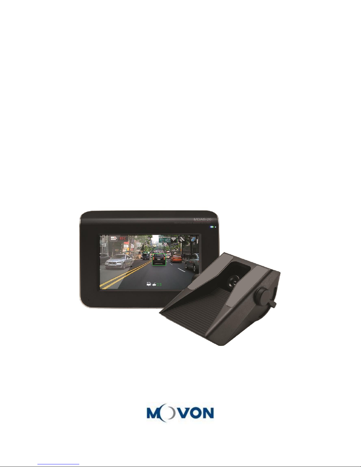
Movon Advanced Driver Assistance System (MDAS) helps drive safely by using a computer image
recognition technology to recognize unintended lane departure and forward collision and provides all-in-
one safety driving solution containing the DTG (Digital Tachograph) and DVR (Digital Video Recorder).
1.2 Notice
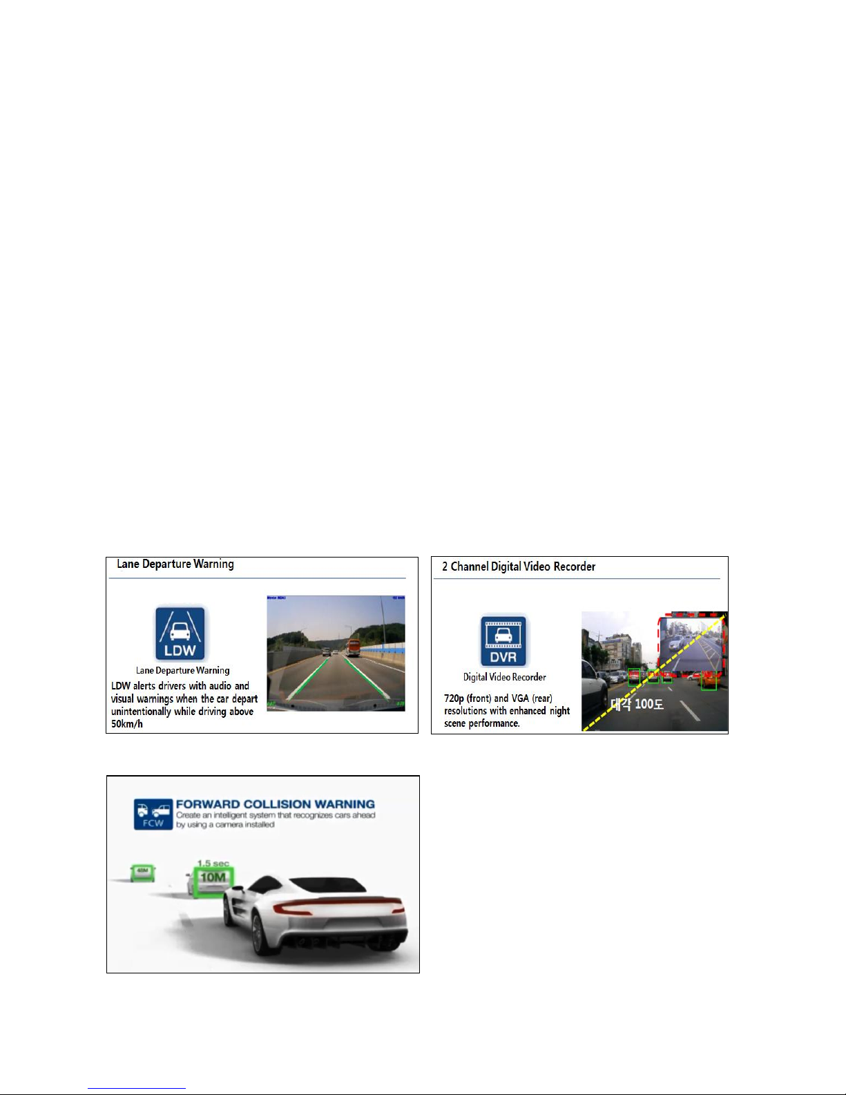
MDAS-20 is a driving assistant product with functions including lane departure warning, forward collision
warning and driving video recording.
MOVON doesn’t cover the defects and damages caused by careless drivers, traffic violations, illegal
activities, misuses and abnormal uses. MDAS-20 gives the warning as beep sounds when the vehicle
changes the lane without proper signaling. The final operation and judgment will be made at the
discretion of the driver. Also, please note that the DVR function is under the privacy rights and personal
responsibilities that it can/may be used as reference images to reflect driving circumstances.
Chapter 2. MDAS-20 Features
2.1 Main functions
2.1.1 LDW (Lane Departure Warning)
2.1.2 DVR (Digital Video Recorder)
2.1.3 FCW (forward collision warning)

July 2014Document v1.1
Chapter 3. Components
3.1 MDAS-20 main unit
3.2 MDAS-20 camera
3.3 Power/Signal cable
3.4 User manual
3.5 Accessories: Micro SD card, Sticker
3.6 Optional products: Rear camera, GPS
modem

July 2014Document v1.1
Chapter 4. Setting
4.1 The process of MDAS-20 installation
Identification of location on power, CAN signal, analog signal
and vehicle signal connected to the vehicle
Fixation of the MDAS-20 main unit in the proper position of
the dash board
Checking and installing the camera, rear camera and 3G
modem to the main unit
Checking the connection of the cables of all systems
Adjusting the knob of the camera to locate the red line on the
horizon
Setting the calibration
1)Checking the connections to the vehicle signal
2)Test driving
(Checking the camera, the rear camera, velocity, and warning
of the lane departure)

July 2014Document v1.1
4.2 Setting the camera
After removing the double-sided tape of the mount, attach the camera in the proper position of
the windshield not to block the driver’s view and secure a good recording position.
In case of commercial vehicles such as heavy trucks and buses, attach the camera above the
position of the wiper.
※
Caution
1)
Place the camera to the back of the rear mirror so that it is lined up with the center of the rear
mirror.
2)
Before attaching, remove the dust on the windshield surface and make the camera fixed tightly
using the double-sided tape.
3)
The position of camera may be different according to the models of the vehicle.
4.3 Setting the main unit
After removing the double-sided tape of the mount, attach the main unit to the recommended
position not to block the driver’s view while driving.
※Caution
1)
Locate the main unit not to interfere with driving.
2)
After removing the dust on the windshield surface, fix the camera tightly using the double-sided
tape.

July 2014Document v1.1
With the adjustment of the bolt, the placement of the main unit can be
changed in all directions.
4.4 Connecting to the car signal
The figure below shows how each component of MDAS-20 should be connected.

July 2014Document v1.1
1. Check the vehicle’s CAN/ANALOG signal at www.mdas.co.kr and go to “MY ACCONT”
You need to sign up to this website in order to create your ID and PW.
Log in
1. Find the right model for the vehicle. Be
aware that CAN files varies depending on
manufacturer, model, manufactured of year,
and type of engines (gas, diesel, etc.).
2. Choose your car at Search section.
3. Download a CAN file by clicking to
the MicroSD card for MDAS-20.
4. Insert the SD card into MDAS-20.
2. In case of the CAN signal, connect the cable of CAN H / CAN L to OBD-Ⅱ.
After the connection is made, you can check it via the CAN SNIFFER.
※ The CAN signal may or may not be indicated in OBD-Ⅱ, so please check the model of the car.
Car signal
Cable color
Car signal
Cable color
CAN High
CAN Low
OBD-II (Normally, No. 6 is CAN High, and No.14 is CAN Low)

July 2014Document v1.1
3. After checking the cable, connect to the proper signals according to the chart below
Car signal
Cable color
Car signal
Cable color
LEFT direction
Right direction
Speed
RPM
Break
HBA
DEB_TX
DEB_RX
4. In order to make the connection to the signals, open the Shield/ Fuse cover/Glove Box
5. After checking the cables, connect to the proper signals according to the chart below.
Car signal
Cable color
Car signal
Cable color
ACC / IG1
12V / 24V IN
GND
Connecting IG1 and 12V IN to the fuse Connecting GND to the ground

July 2014Document v1.1
Ex) Position of the signal lights (Bottom of the steering wheel)
Checking the cables for the signal lights using
the test equipment
6. Connecting the camera cable to the main unit cable.
[Main Unit Cable] [Camera Cable]

July 2014Document v1.1
7. Connecting the multi cable to the main unit.
[Main Cable] [Main Unit]
8. After all the connections are made, organize the cables.
9. After organizing the cables, assemble Shield/ Fuse cover/Glove Box to their former positions.

July 2014Document v1.1
4.5 Calibration
1. Turn on the product and select the “Calibration”icon at the below page.
2. Select the “Calibration”again at the below page.
3. Select the vehicle model and manufacturer and click the arrow on the upper right-hand corner.

July 2014Document v1.1
4. Setup the current date and time.
5. Select the appropriate speed unit.
6. Adjust the lens of the camera to place the horizon between the two red dotted lines. Then, click
the arrow on the upper right-hand corner
7. Adjust the yellow dotted line to place the horizon between the two red dotted lines. Then, click
the arrow on the upper right-hand corner.

July 2014Document v1.1
8. Adjust the value of the hood line to align the yellow dotted line to the boundary of the hood.
9. Fill in the vehicle width and adjust the value of camera height for the location of the camera.
10. If you want to change the warning timing for LDW, please click the lane marker. Default value is
0 (at 3) and every unit changes 4 inch (10cm) length from its side.

July 2014Document v1.1
11. If you want to change the warning timing for FCW, please click the distance range marker.
Default value is 1.2 sec. and every unit changes 0.3 sec.
12. After checking if the car signals are connected properly, press the next button and close the
calibration mode.

July 2014Document v1.1
13. Adjustment of the sensitivity of the lane departure warning.
1) Click the ADAS icon
2) Set left and right sensors in LDW
The beeping sounds will go off more quickly as the lanes are set closer to the vehicle.
3) Set TTC (Time to Collision) in FCW
The beeping sounds will go off more quickly as the host vehicle is set close to the vehicle.
4) Set the Alert Tone

July 2014Document v1.1
4.6 Operation test
1. Adjust the knob of camera so that the middle of the red line is aligned with the horizon. You can
easily open the cab of adjusting knob and tighten the bolt.
2. Check the speed in the top of right.

July 2014Document v1.1
3. Check to see if the signal lights are working.
4. Check if virtual lanes are displayed in case the vehicle is driving more than 60Km/h.
Table of contents
Other Movon Automobile Accessories manuals