Movon MDAS-9 User manual

BHM
07/25/2019
NTV-DOCxxx
3950 NW 120th St. Coral Springs, FL 33065 TEL 561-955-9770 FAX 561-955-9760
www.nav-tv.com i[email protected]m
Quick Install Guide
Overview
The MDAS-9 by Movon is an advanced driver safety system designed to save lives, increase awareness of bad
driving habits & record driving statistics (with video) for fleet management users and conventional drivers
alike. This installation manual highlights the most important information required and assumes an
experienced installer uses common industry practices for a successful integration.
Kit Content
GPS Antenna
(optional)
Rear Camera kit
(optional)

BHM
07/25/2019
NTV-DOCxxx
Main (front) camera unit preparation
•The main unit comes prepared for bus/large truck setup (cable routing) or vehicles with mostly vertical
windshields. To set up the unit for an average truck or passenger vehicle, dismantle partially as shown
below:
4. Reroute the main cable (and
rear camera cable, if adding)
around unit to front (glass side)
5. Press tightly into channels
when routing cables. Remove
front camera dust sticker.
6. Replace 1 cover only
removed from step 3. Replace 2
screws. Leave the remaining
covers off until the last step.
1. Remove cover
2. Remove (2x) screws,
remove plastic cover
3. Remove (2x) screws, pry
plastic mounting frame off
unit from corners
Rear camera
connection

BHM
07/25/2019
NTV-DOCxxx
Vehicle Installation
1. Clean the spots on the windshield with the provided alcohol wipe where you plan to
mount the hardware. Remove the red 3M tape and mount the main unit underneath the
rearview mirror as centered (left/right) and straight as possible (if it must be off center by
a few inches, that’s okay – measurements will be taken later). Be certain not to obstruct
the drivers view.
2. Run the main-unit cable across the headliner and down to the driver side under-dash. This may require
removing the A-pillar temporarily. Follow factory harnesses, always run behind any airbags.
3. Run the rear camera cable to the rear of the vehicle (if using it for a true rear camera) or
loop it back to where the rear camera will be mounted for an interior-view camera. For
the rear camera placement, the arrow icon must be at the top (ignore the direction of the
arrow icon –just keep it at the top) for mounting. Mount like shown here (right).
4. Attach the mount (from the plastic bag) and stick the LCD indicator on the windshield in the
driver’s line-of-sight, usually close to the A-pillar so it can be easily seen and controlled if
required. Run this cable down to the driver’s under-dash as well.
5. Once both cables are run to the under-dash, connect them to
the provided PCI unit at the proper ports.
6. Connect the (optional) GPS antenna somewhere within a few inches of the main unit (stuck to windshield).
Connect to the main unit via the GPS port (3.5mm).
PCI unit
Main Cable
LCD Indicator

BHM
07/25/2019
NTV-DOCxxx
NOTE: this connection uses inductance. There is no need to strip the CAN wires –just
open the black box, lay the CAN High and Low in the channels, then close the box.
7. Connect the provided Power/Ground harness connection to a
chassis ground (black wire) and Ignition source (red wire). The
circuit must provide ~3 Amp @12v. Connect the plug to the PCI
unit at the ‘Power’ port.
Installation: for CAN-equipped vehicles
Many vehicles are available in Movon’s database for using the CAN bus for vehicle signals (turn signals, brake and speed
sense). This makes for a much faster installation. See below for checking availability of a downloadable CAN file for your
vehicle. NOTE: not all vehicles are available on the database currently, even if the vehicle has CAN. The list is constantly
updated, so if the vehicle isn’t there now, it may be later. The installation may still be completed using analog
connections instead of CAN –see next section.
•Check to see if there is a CAN file available by opening a Chrome browser and going to info.mdas.co.kr:
USER: [email protected]
PASS: profit
1. Choose the vehicle make and model into the selector at the left.
2. Click the page icon (at right) and the database information will show CAN wire location information (if available)
and download the ‘CAN File Download’ file at the bottom. NOTE: this filename will always be ‘mdasinfo.dat’ and
cannot be renamed –so if you’re installing another MDAS-9 and using this computer to set up, make a separate
file folder (every time) with the vehicle year and model, and put this file inside of it.
3. If the there is a CAN file available, connect the provided CAN harness (contactless reader) to the (transmission)
CAN bus wires –either where stated or at the OBD2 port, typically pins 14 & 6, if the vehicle is available on the
MOVON database only.
4. Connect the 4-pin plug from the CAN harness to the ‘CAN’ port on the PCI unit.
•If the vehicle is not listed in Movon’s database, you must use the provided Analog harness, see next
section. NOTE: vehicles that are 1 year (or so) off, may still work for CAN access!

BHM
07/25/2019
NTV-DOCxxx
NOTE: the unit will beep about once a second
while in calibration mode –this mode will
remain until the USB cable is disconnected.
*The MDAS-9 unit will show up in Windows Device Manager as ‘USB
Ethernet/RNDIS…’ under Network Adapters once installed properly.
Installation: For Analog signals (no CAN)
If the vehicle has no CAN bus or there is no CAN file available, you must tap turn signal (left and right), brake and speed
signal manually (various locations). Speed sense can be accessed with an optional GPS antenna instead of the SS wire,
this would also be beneficial for location of the vehicle along with recorded video and fleet management
information.
1. With a digital multimeter or test light, locate the brake signal wire that activates when the brake is
pressed (vehicle may need to be ON). Connect and insulate the black/white wire to this vehicle’s
wire. This may be a (+) or (-) signal.
2. With a digital multimeter or test light, locate the left turn signal wire that activates with the left
turn signal. Connect and insulate the blue/white wire to this vehicle’s wire. This may be a (+) or (-)
signal.
3. With a digital multimeter or test light, locate the right turn signal wire that activates with the
right turn signal. Connect and insulate the blue wire to this vehicle’s wire. This may be a (+) or
(-) signal.
4. Locate the VSS wire. Connect and insulate the brown/white wire to this vehicle’s wire.
5. NO other wires are required for typical installation –ground the remaining wires.
MDAS-9 Calibration
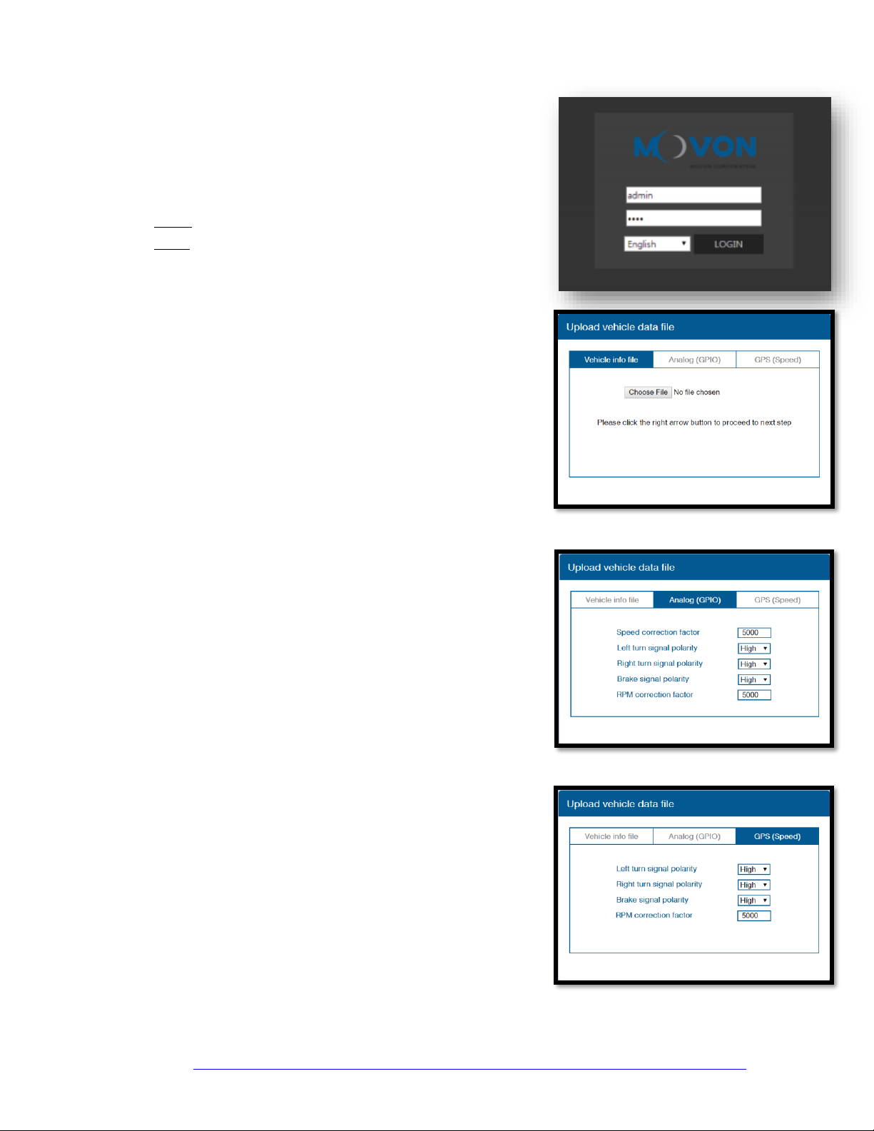
MDAS-9 Calibration requires:
-a laptop with an internet connection and a browser (Chrome is best)
-micro-USB cable
-tape measure
-parking the car with a clear, open stretch of about a 50-yard unobstructed view (try to park close to your facility
to keep the internet connection accessible –at least during the calibration driver installation)
-a partner to drive the vehicle while speed correction is performed
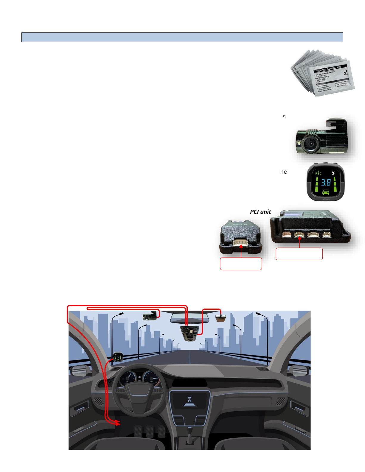
•Before beginning, insert the provided micro-SD card into the main
unit in the location shown here (right) until it clicks and turn the
Ignition ON. Wait for the prompt, then press and release the
center button one time. After the successful prompt and the unit
reboots, continue to step 1.
1. Park the vehicle in a spot with a clear stretch of unobstructed line-of-sight (about 50 yards). Leave the vehicle
running.
2. Connect the USB cable to the Mirco-USB port on the side of the main unit
(windshield) and the other end to the laptop. If on a windows 10 machine, it
should automatically install the required driver. If not or on an older
machine, go to movon.co.kr, go to the ‘ADAS’ tab at the top then to
‘Downloads’ under Support. Download the appropriate zip file (contains
driver) and extract it fully for your version of Windows OS (if using the
7/8 driver, install the .exe file). If WIN10, once downloaded,
disconnect/reconnect the USB and it should automatically install, or find the unit
in Device Manager and right-click, Update Driver and browse for driver locally*.

BHM
07/25/2019
NTV-DOCxxx
3. Open Chrome browser again and type in ’10.0.0.1’ into the URL
bar. If the driver was installed properly, the MOVON calibration
screen will appear. Input credentials and press LOGIN:
USER: admin
PASS: 1234
4. Select Vehicle Signal Type: there are 3 wiring options for
installation: CAN-BUS / Analog (GPIO) / GPS (Speed). Select the
proper calibration option based off which was installed: CAN (if
CAN file is available), Analog (if analog signals were tapped) or GPS
(if a GPS antenna was used, typically with analog signals)
Vehicle Data File (CAN-BUS)
For CAN-BUS connection, choose the ‘Vehicle info file’tab and select
‘Choose File’ to upload the previously downloaded ‘mdasinfo.dat’ file (see
‘CAN-Equipped vehicles’ section).
Analog (GPIO)
When using Analog signals, uploading a CAN file isn’t required. Click the
Analog (GPIO) tab. Enter speed correction factor value and RPM correction
value (leave alone if unsure). Change polarity for turn signals and brake
signal based on the vehicle. (HIGH = Positive trigger, LOW = Negative
trigger)
GPS (Speed)
If using the optional GPS antenna, click the GPS tab. Change polarity for
turn signals and brake signal (HIGH = Positive trigger, LOW = Negative
trigger). Enter RPM correction value (leave alone if unsure).
Continue the calibration via the prompts on setup screen via laptop. For more detailed information, download the full
installation manual at https://navtv.com/media/products_file/2019/04/29/MDAS-9_Installation_Manual.pdf
Other manuals for MDAS-9
3
This manual suits for next models
1
Table of contents
Other Movon Automobile Accessories manuals
Popular Automobile Accessories manuals by other brands

Rola
Rola 59004 instructions

Mountain Top
Mountain Top Mountain Top Style installation manual

AUTOACCESS
AUTOACCESS FORCE PRO+ FORD RANGER 2019 CLOSED installation manual

Metra Electronics
Metra Electronics 99-6520B installation instructions

GO2
GO2 Rangierhilfe RH3 operating instructions

TowCar
TowCar TowBox-v3 instructions