Movon MDAS-9 User manual

MDAS-9 Installation Guidebook

- 2 -
CONTENTS
1General ..........................................................................................................................6
2Product .......................................................................................................................... 7
2.1 Specification........................................................................................................................ 7
2.2 Product components ........................................................................................................ 8
2.3 Main Unit & Main Cable...................................................................................................9
2.3.1 Main Unit.......................................................................................................................9
2.3.1.1 Parts description................................................................................................. 9
2.3.1.2 Mounting Frame and Back Cover.................................................................... 9
2.3.1.3 LED Description.................................................................................................10
2.3.2 Main Cable..................................................................................................................10
2.4 Contactless CAN Reader.................................................................................................10
2.5 Indicator.............................................................................................................................10
2.6 Peripheral Component Interconnect Box (PCI Box) .................................................11
2.7 External Fuse ....................................................................................................................12
2.8 Technical Cleaning Wipe ................................................................................................12
2.9 Vibrator (Optional)..........................................................................................................13
2.10 GPS (Optional)..................................................................................................................13
2.11 Video Out Cable (Optional) ...........................................................................................13
2.12 FMS Cable (Optional)......................................................................................................13
2.13 Micro SD Card (Expendable) .........................................................................................14
2.14 Wi-Fi Dongle (Optional for calibration).......................................................................15
2.15 Micro 5 pin USB Cable (Optional for Calibration).....................................................15
3Installation...................................................................................................................16
3.1 System Connection Scheme..........................................................................................16
3.2 Installation Procedure ....................................................................................................16
3.3 Wiring Combination and Description..........................................................................17
3.3.1 16Pin Main Cable.......................................................................................................17
3.3.2 5Pin Analog Cable......................................................................................................17

- 3 -
3.3.3 4Pin CAN Cable...........................................................................................................18
3.3.4 3Pin Power Cable.......................................................................................................18
3.3.5 Contactless CAN Reader...........................................................................................18
3.3.6 Wiring Combination..................................................................................................20
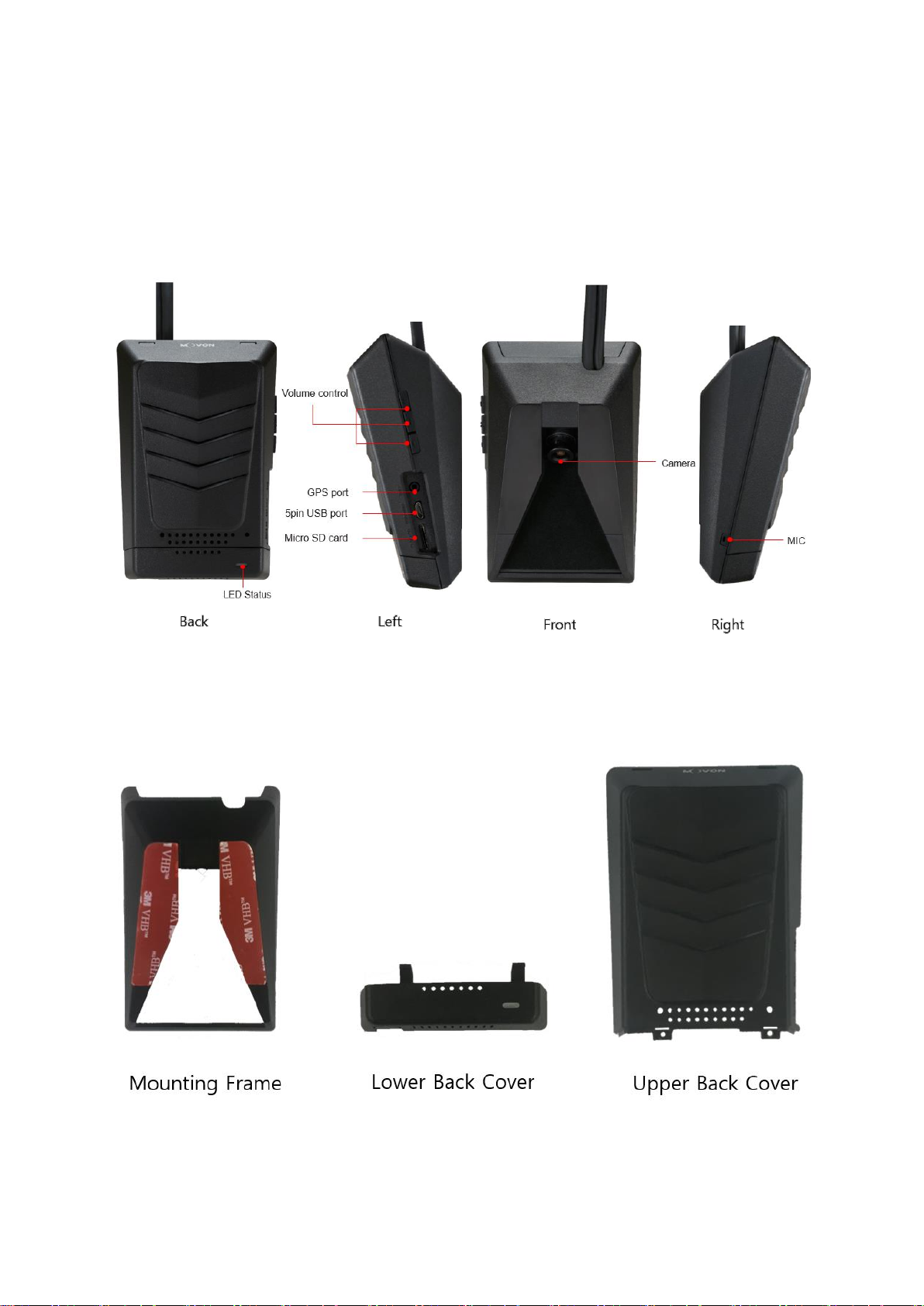
3.4 Attach MDAS-9.................................................................................................................21
3.5 Parts connection..............................................................................................................24
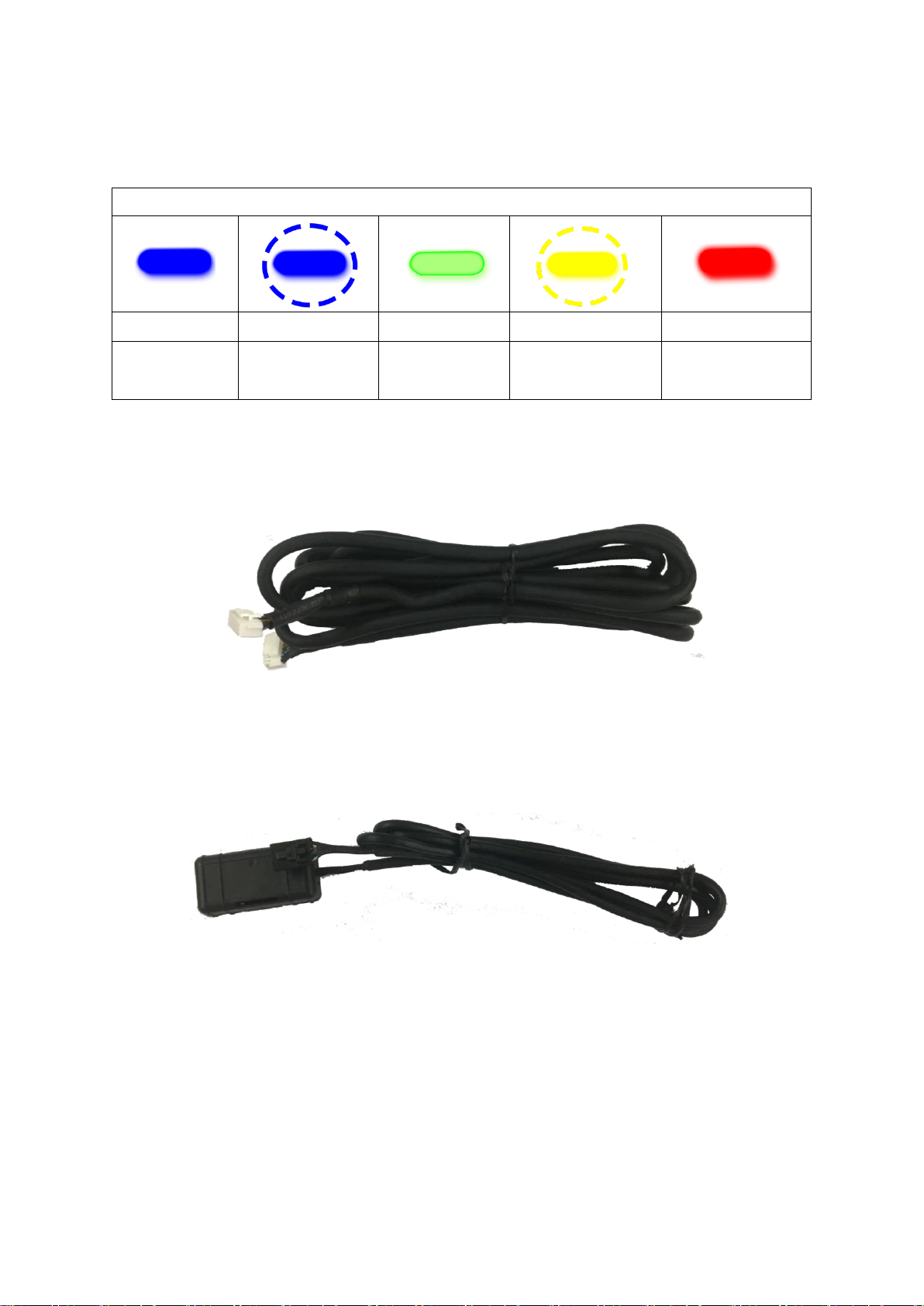
3.5.1 Indicator ......................................................................................................................24
3.5.2 Vibrator........................................................................................................................24
3.5.3 FMS Cable....................................................................................................................25
3.5.4 Video-Out Cable.........................................................................................................25
3.6 Connect Rear Camera to MDAS-9................................................................................26
3.7 Reset MDAS-9...................................................................................................................28
4PC and Android Phone Calibration ..............................................................................30
4.1 Driver Setup (ONLY SUPPORTS WINDOWS OS).........................................................30
4.2 Calibration Setup .............................................................................................................30
4.2.1 Access MDAS-9 Calibration page via PC ...............................................................30
4.2.2 Access MDAS-9 Calibration page via Android Phone ........................................30
4.2.3 Select Vehicle Signal Types......................................................................................33
4.2.3.1 Vehicle Data File (CAN-BUS)...........................................................................33
4.2.3.2 Analog (GPIO) ....................................................................................................34
4.2.3.3 GPS.......................................................................................................................34
4.2.4 Vehicle Information Check ......................................................................................35
4.2.4.1 Verify Speed Signal...........................................................................................35
4.2.4.2 Verify Turn Signal..............................................................................................35
4.2.5 Camera Location and Vehicle Measurement ......................................................36
4.2.6 Camera Angle .............................................................................................................36
4.2.6.1 Fine Camera Angle............................................................................................37
4.2.7 Hood Line ....................................................................................................................38
4.2.8 Rear Camera Setup ...................................................................................................38
4.2.9 Lane Departure Warning (LDW) Sensitivity.........................................................39

- 4 -
4.2.10 Forward Collision Warning (FCW) Sensitivity......................................................39
4.2.11 Safety distance alert setup......................................................................................40
4.2.12 Pedestrian collision warning setup........................................................................40
4.2.13 Advanced ADAS setup..............................................................................................41
4.2.14 DVR (Dashcam) setup...............................................................................................41
4.2.15 Fleet management setup.........................................................................................42
4.2.16 Miscellaneous Settings.............................................................................................43
4.2.17 MDAS Setup Complete.............................................................................................43
4.3 Setting Modification........................................................................................................44
4.3.1 Menu Description......................................................................................................45
4.3.2 Update Firmware.......................................................................................................45
4.3.3 Default MDAS Settings .............................................................................................46
4.3.4 Re-calibration .............................................................................................................46
4.3.5 Change settings from warning setups...................................................................47
5How to Download CAN Data........................................................................................48
5.1 Register in Vehicle Database.........................................................................................48
5.2 Download CAN Data file.................................................................................................48
6Recognize MDAS-9 in computer ..................................................................................51
6.1 Computer with Windows XP, 7, 8, 8.1 ........................................................................51
6.2 Computer with Windows 10 .........................................................................................51

- 5 -
No
Version
Date
Contents
Written
Note
1
2.1.5
17.08.05
Initial Release
John
2
2.1.6
17.08.08
Modified a picture (Power Cable, Smart
phone Calibration, PC Calibration)
John
3
2.1.7
17.08.09
Addition
FMS cable
John
4
2.1.8
17.08.10
Addition
Recording Hours
John
5
2.1.9
17.08.17
Modified product components
John
6
2.2.0
17.09.14
Modified product accessory
Hugh

- 6 -
1General
MDAS installation requires wiring electric signals of vehicles. Please contact your local
distributor or authorized installers to install. Movon will hold no liability of any damage
occurred during installation proceeded by users, or unauthorized installers.
MDAS is developed to give only warnings to drivers. The final decision to maneuver or
control shall be made by drivers themselves. Furthermore, MDAS is not capable to
provide 100% detection rate of lane markings, vehicles, and MDAS recognition
performance can be fluctuated due to road conditions, inclement weather, poor
installation, etc. Please ensure that keep eyes forward while driving rather than only
relying on MDAS.

- 7 -
2Product
2.1 Specification
CPU
Cortex A7 Quad-Core
Audio Out
Speaker
Camera
Front
1280 x 720 (HD)
Rear
1280 x 720 (HD)
Power
Input Range
DC 10V ~ 36V
Power
Consumption
400mA @ 12V Max
3mA @ 12V Idle State
Format
Video
AVI (h.264 codec)
Audio
PCM
Storage
4~128GB Micro SD card support
Input / Output
Main
Micro 5pin USB port, Micro SD Card,
GPS port
PCI Box
Main Cable, Vibrator, Analog, Indicator, FMS,
Video OUT, CAN, POWER, Fuse
Size
Body
80 x 120 x 50 mm
Temperature
Operation
-20℃~ 70℃(-4℉~ 158℉)
Storage
-40℃~ 85℃(-40℉~ 185℉)

- 8 -
2.2 Product components
Main unit
Basic cable
(3P Power, 5P
Analog)
Micro SD card
Indicator
Technical cleaning
wipe
PCI Box
CAN Cable
Rear Camera
(Optional)
Contactless CAN
Reader
(Optional)
Video Out Cable
(Optional)
GPS
(Optional)
Vibrator
(Optional)
Micro 5PIN USB
cable
(Optional for
installers)
Wi-Fi Dongle
(Optional for
installers)
FMS Cable
(Optional)
External Fuse
(Optional)

- 9 -
2.3 Main Unit & Main Cable
2.3.1 Main Unit
2.3.1.1 Parts description
2.3.1.2 Mounting Frame and Back Cover

- 10 -
2.3.1.3 LED Description
2.3.2 Main Cable
2.4 Contactless CAN Reader
2.5 Indicator
Read user manual to see more description and functions.
LED Status
Illuminate
Blink
Illuminate
Blink
Blink
Booting
Turn signal (L, R)
Before booting
Working mode
Initialization
Calibration Mode
Firmware Update

- 11 -
Indicator Error Table
Camera
Connection
Error
CAN
Communication
Error
Camera
View Block
Error
Indicator
Communication
Error
Low
Visibility
Indication
2.6 Peripheral Component Interconnect Box (PCI Box)
Peripheral Component Interconnect Box (PCI Box) is to connect the cables and
accessories.

- 12 -
PCI BOX LED status table
Color
status
Yellow
In case of wiring only constant power
Green
In case of wiring constant power and ACC power
2.7 External Fuse
MDAS-9 provides with an External Fuse to prevent from short circuiting the vehicle
electrical system.
2.8 Technical Cleaning Wipe
MDAS-9 provides Technical Cleaning Wipe for cleaning and removing dust, finger
print on windshield.

- 13 -
2.9 Vibrator (Optional)
* NOTE: Need Vibrator gender cable to use this and need to enable in Calibration.
Read details in Chapter 4. Calibration
2.10 GPS (Optional)
* Important, in case of use GPS for speed signal, warning timing can be inaccurate
in decelerating circumstances.
2.11 Video Out Cable (Optional)
Transmit analog video to another device using RCA connector.
2.12 FMS Cable (Optional)
Transmit ADAS event data to Fleet Management System through RS-232 and CAN
interfaces.

- 14 -
2.13 Micro SD Card (Expendable)
* Micro SD card is expandable, only first 3 months are guaranteed. It is
recommended to format micro SD card regularly and replace it when it cannot be
recognized in MDAS.
** Micro SD card speed shall be above Class 10 and it is recommended to use MLC
type.
Total Recording Hours (approximately)
Memory Storage
Normal + Event + User
1CH
2CH
8GB
About 1 hour and 45 minutes
About 45 minutes
16GB
About 3 hours and 40 minutes
About 1 hour and 45 minutes
32GB
About 7 hours and 30 minutes
About 3 hours and 40 minutes
64GB
About 15 hours and 20 minutes
About 7 hours and 30 minutes

- 15 -
2.14 Wi-Fi Dongle (Optional for calibration)
Use for Calibration procedures for Android OS Phones.
Application can be downloaded in Google Play Store.
2.15 Micro 5 pin USB Cable (Optional for Calibration)
* NOTE: You can use a common USB cable that supports data transmission.
Use for Calibration procedures for Windows OS computers.
Before use, please install RNDIS driver, first. (See Chapter 4.1)

- 16 -
3Installation
3.1 System Connection Scheme
3.2 Installation Procedure
①Check which types of signals the vehicle provides (CAN/Analog)
②Connect vehicle signals (See Chapter 3.3 Wiring Combination)
③Attach MDAS-9 (and indicator if needed) to the vehicle
④Connect cables with MDAS-9
⑤Access MDAS-9 using Micro 5pin USB cable or Wi-Fi dongle
⑥Calibration (See Chapter 4. Calibration procedure)
⑦Test drive

- 17 -
3.3 Wiring Combination and Description
3.3.1 16Pin Main Cable
* NOTE: Label color could be different due to production, please check label
tags before wiring.
3.3.2 5Pin Analog Cable
Color
Label
Connection Description
Blue
SIG_R
To analog right turn signal
Light Blue /
White Stripe
SIG_L
To analog left turn signal
Brown /
White Stripe
SPEED
To analog speed signal,
be careful with old vehicles that do not have speed
sensor
Violet
RPM
To analog RPM signal
Black /
White Stripe
BRAKE
To analog BRAKE signal

- 18 -
3.3.3 4Pin CAN Cable
Color
Label
Connection Description
White
CAN_H
To CAN High wire
Support CAN J1939 standard
& CAN 2.0 (Support Version A, B)
Green
CAN_L
To CAN Low wire
3.3.4 3Pin Power Cable
Color
Label
Connection Description
Yellow
POWER
Power for the main unit. To ignition (ACC) power wire
that turns off when key is at OFF
Red
IGN
Power for optional accessories. To ignition (ACC) power
wire that turns off when key is at OFF
Black
GND
To ground source
* Please ensure that is connected properly to ground,
or it could damage the vehicle and MDAS.
*Note : Connect Power cable and IGN cable together to ignition (Accessory)
power.
* There are different ignition powers, it is recommended to use an ignition
power (ACC, IG1) that does not drop power shortly when the engine turns on.
3.3.5 Contactless CAN Reader

- 19 -
3.3.5.1 Wiring with Contactless CAN Reader
①Connect Contactless CAN Reader to PCI box of MDAS-9.
②Remove double-sided tape
③Attach the vehicle’s CAN wire as straight as possible to the double-
sided tape by aligning with the hole marked in red.

- 20 -
* Like this picture, place CAN_L to the left and CAN_H to the right!
④After case assembly, if installing CAN_H and CAN__L correctly, the
red LED lights operates on the lower left side of the case as shown in
the picture when the vehicle is “Key on”.
* After checking on operating of LED lights correctly, tie with a cable
tie marked in yellow.
(If CAN_H and CAN_L wires are attached in reverse, LED lights does
not work.)
3.3.6 Wiring Combination
* NOTE: See cable description table below.
* NOTE: You can see Vehicle Database to check CAN-BUS availability.
Visit http://info.mdas.co.kr and check information before installation.
* NOTE: If you don’t use whole analog cable, you should wire the remaining
cable of 5Pin analog with ground.
No.
Speed
Turn signal
Recommended connection
Other manuals for MDAS-9
3
Table of contents
Other Movon Automobile Accessories manuals
Popular Automobile Accessories manuals by other brands

Rola
Rola 59004 instructions

Mountain Top
Mountain Top Mountain Top Style installation manual

AUTOACCESS
AUTOACCESS FORCE PRO+ FORD RANGER 2019 CLOSED installation manual

Metra Electronics
Metra Electronics 99-6520B installation instructions

GO2
GO2 Rangierhilfe RH3 operating instructions

TowCar
TowCar TowBox-v3 instructions