MP DRY CABINET II User manual
page 1/22
DRY CABINET II
User´s manual
MP Elektronik Technologie, s.r.o.
Dlouhá 219
678 01 Blansko - Klepačov
Czech Republic
Tel: +420 516 416 937
Fax: +420 516 417 641
E-mail: [email protected]
www.mpelektronik.cz

User´s manual
MP DRY CABINET II
Content
1 Introduction.....................................................................................................................................................................3
1.1 Intended Use of the Device........................................................................................................................................3
1.2 Acts, Regulations and Standards................................................................................................................................3
1.3 Type of the device......................................................................................................................................................3
2 Safety at Work, Fire Protection.....................................................................................................................................4
2.1 Obligations of the Operator........................................................................................................................................4
2.2 Qualification Requirements on Employees................................................................................................................4
2.3 Conditions of Safe Operation of Electric Devices.....................................................................................................4
2.4 Fire Protection............................................................................................................................................................4
2.5 Safety Labels Used and Their Significance...............................................................................................................4
3 Technical Specification...................................................................................................................................................5
4 General Description........................................................................................................................................................7
4.1 Construction layout....................................................................................................................................................8
5 Preparation for Use.......................................................................................................................................................10
5.1 Storage......................................................................................................................................................................10
5.2 Transport and Assembly..........................................................................................................................................10
5.3 Power Supply Connection........................................................................................................................................11
5.4 Operational Check....................................................................................................................................................12
6 Instructions to use.........................................................................................................................................................13
6.1 Control Panel Description........................................................................................................................................13
6.2 Log in of the Engineer..............................................................................................................................................14
6.3 Setting......................................................................................................................................................................15
6.4 Saving measurement data on storage device............................................................................................................18
7 Packing List...................................................................................................................................................................19
7.1 Parts of Delivery......................................................................................................................................................19
8 Delivery, Service and Warranty Conditions...............................................................................................................20
page 2/22
User´s manual
MP DRY CABINET II
1 Introduction
The purpose of the User´s manual is to inform the user of the properties, use, correct assembly procedure and
maintenance of MP DRY CABINET II. The User´s manual contain description of construction, principle of operation,
technical parameters of the device.
1.1 Intended Use of the Device
Drying cabinet MP DRY CABINET II is intended for drying and storage of PCB´s and electronic components at very
low relative humidity without having to use of vacuum packaging.
1.2 Acts, Regulations and Standards
The acts, regulations and standards mentioned below are in force in the European Union. In other countries, the local
legislation dealing with the given issues is valid. The device complies with directives and government regulations and
harmonized technical standards listed in the table.
Name Designation
On safety of low voltage electric devices Directive 2006/95/EC (GR No. 17/2003 Coll.)
Low voltage electrical installations - revision EN 33 2000-6
Protection against electric shock EN 33 2000-4-41 ed.2
Revision of electric devices EN 33 1500
Protection class by coverage EN 60529/1993
1.3 Type of the device
MP DRY CABINET I. 1x door
MP DRY CABINET II. 2 x doors
MP DRY CABINET IV. 4 x doors
page 3/22

User´s manual
MP DRY CABINET II
2Safety at Work, Fire Protection
2.1 Obligations of the Operator
°
The operator shall be obliged to secure the compliance with generally binding safety regulations during the work
with the device.
°
The operator shall be obliged to perform visual checks of the device and the basic maintenance.
°
The operator shall be obliged to determine responsibilities of persons for the commissioning, maintenance,
cleaning and regular maintenance, setting and adjusting before the commissioning in order to secure the safety of
persons and property.
°
The operator shall be obliged to provide that the relevant activities are performed by persons with adequate
qualification.
°
The operator shall be obliged to provide safe access to the device and sufficient space for the access to the
device.
°
The operator shall be obliged to renew the state of the safety markings upon their damage or illegibility in
accordance with their original state.
2.2 Qualification Requirements on Employees
°
The device assembly may only be performed by an expert acquainted with the operation, safety and other
regulations, if any, concerning the safety at work, valid for the place in which the device is to be located or
otherwise related to the place of work.
°
The assembly and wiring of the electrical configuration of the device shall only be performed by an employee
with qualification complying with the valid legislation of the country in which the device is operated.
°
The device may only be operated independently by employees with full physical and mental capacity, older than
18, demonstrably trained for the given type of work and acquainted with the Service Instructions which shall be
kept in a well-accessible place.
2.3 Conditions of Safe Operation of Electric Devices
°
The User´s manual shall be available to all staff performing activities related to the installation, operation and
maintenance of the electric device, at any time.
°
The installation, operation and maintenance shall only be provided by persons qualified for these activities in
accordance with valid legislation of the country in which the device is operated.
°
It is PROHIBITED to interfere in any way with the construction of the device.
°
It is PROHIBITED to perform maintenance, cleaning and repairs if the electric supply is not disconnected and
if the related technological equipment is not secured to be off.
°
It is PROHIBITED to have the device work with open or removed covers – blanking plates.
°
It is PROHIBITED to touch the inner sheathing of the device and the inner side of the door while the heat may
cause burns.
2.4 Fire Protection
•
The device and its operation do not increase the fire hazard.
•
ATTENTION, an electric device, do not extinguish with water or foam.
2.5 Safety Labels Used and Their Significance
Do not extinguish with water or foam!
page 4/22

User´s manual
MP DRY CABINET II
3 Technical Specification
MP DRY CABINET I.
Overall dimensions (š x v x d) 700 x 1070 x 690 mm
Inner dimensions (š x v x d) 640 x 800 x 520 mm
Weight 90 kg
Effective capacity 230 l
Number of shelves 3 (perforated metal sheet)
Power supply 230V 50Hz
P max 750 W
Humidity sensor sensitivity +/- 0,5% RH
Temperature sensor sensitivity +/- 0,1 K
Temperature range setting 0 – 60 °C
Working temperature range 15 – 45 °C
Average power consumption energy when heating off 50 W/h
Average power consumption at 40 °C 180 W/h
Average power consumption at 50 °C 280 W/h
Average power consumption at 60 °C 350 W/h
Service space required around the device 650 mm
MP DRY CABINET II.
Overall dimensions (š x v x d) 700 x 1920 x 690 mm
Inner dimensions (š x v x d) 640 x 1650 x 520 mm
Weight 180 kg
Effective capacity 460 l
Number of shelves 5 (perforated metal sheet)
Power supply 230V 50Hz
P max 750 W
Humidity sensor sensitivity +/- 0,5% RH
Temperature sensor sensitivity +/- 0,1 K
Temperature range setting 0 – 60 °C
Working temperature range 15 – 45 °C
Average power consumption energy when heating off 50 W/h
Average power consumption at 40 °C 180 W/h
Average power consumption at 50 °C 280 W/h
Average power consumption at 60 °C 350 W/h
Service space required around the device 650 mm
page 5/22

User´s manual
MP DRY CABINET II
MP DRY CABINET IV.
Overall dimensions (š x v x d) 1410 x 1920 x 690 mm
Inner dimensions (š x v x d) 1350 x 1650 x 520 mm
Weight 320 kg
Effective capacity 920 l
Number of shelves 10 (perforated metal sheet)
Power supply 230V 50Hz
P max 950 W
Humidity sensor sensitivity +/- 0,5% RH
Temperature sensor sensitivity +/- 0,1 K
Temperature range setting 0 – 60 °C
Working temperature range 15 – 45 °C
Average power consumption energy when heating off 60 W/h
Average power consumption at 40 °C 200 W/h
Average power consumption at 50 °C 300 W/h
Average power consumption at 60 °C 380 W/h
Service space required around the device 650 mm
page 6/22
User´s manual
MP DRY CABINET II
4 General Description
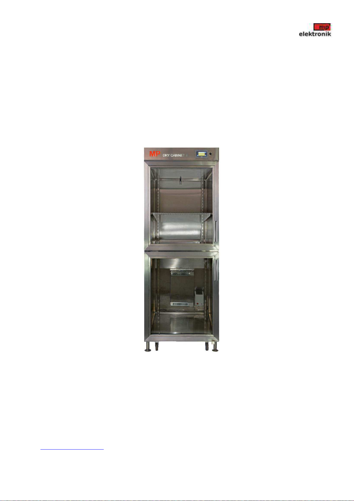
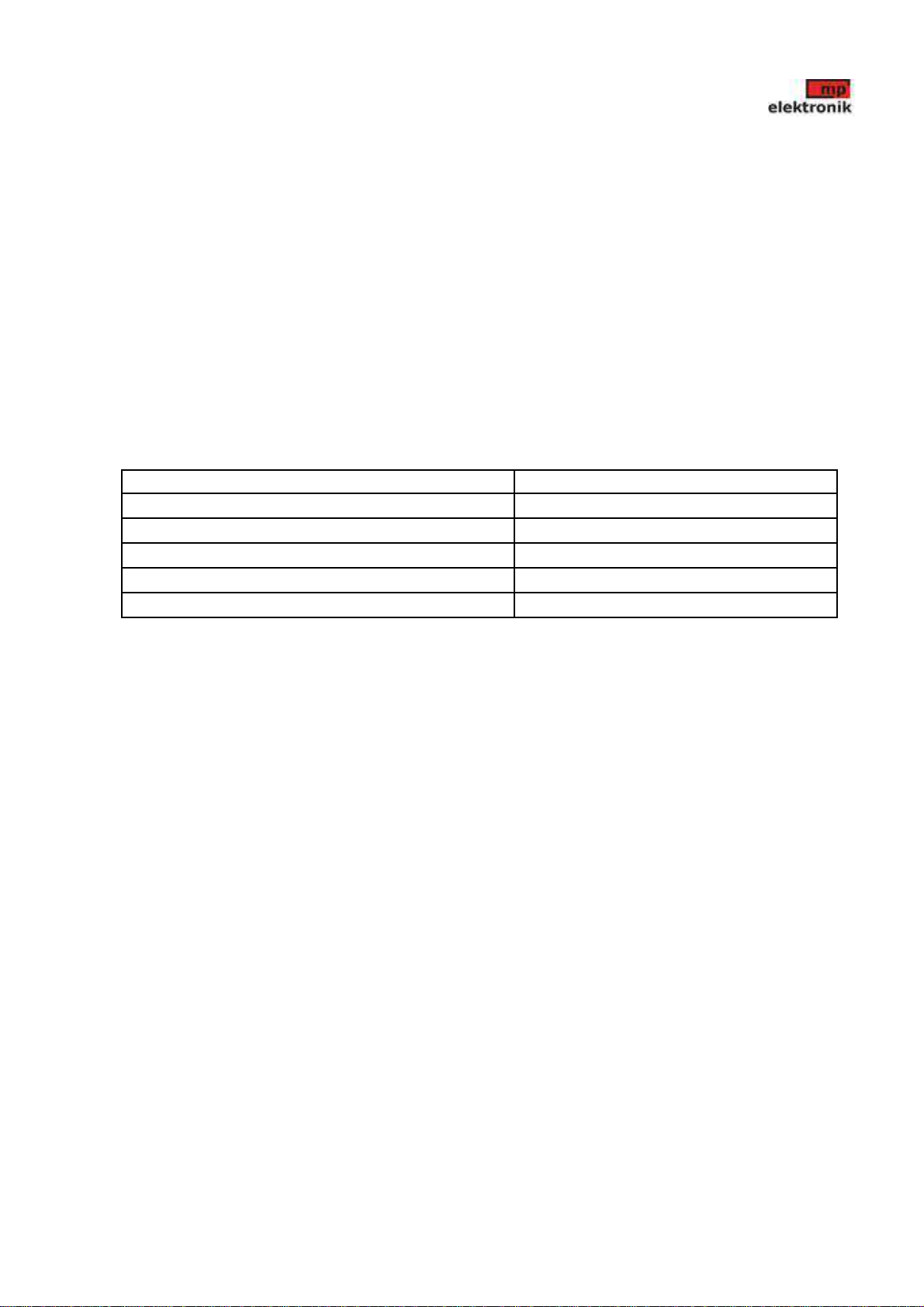
MP DRY CABINET II
Drying cabinet MP DRY CABINET II is a separate drying device for drying of printed circuit board assemblies,
electronic components and ESD components of all classes. The device can be used in operations and processes sensitive to
humidity, during PCB assembly for interoperation storage and storage of sensitive electronic components.
The device can reach a very low relative humidity (0.5% RH) and high temperature (60 ° C) to effectively shorten the
drying time. The equipment is stainless steel with glass doors. The device is equipped with a touch screen with the option
to set the desired temperature, to set frequency of storage pre-set parameters to memory and set the door open alarm.
Progress of temperature and humidity can be monitored on the chart and data record can be exported via the USB
connector to the PC.
page 7/22
User´s manual
MP DRY CABINET II
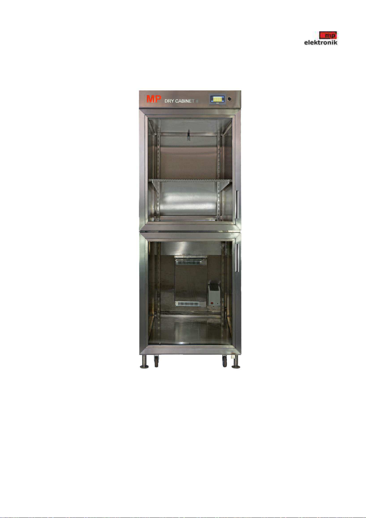
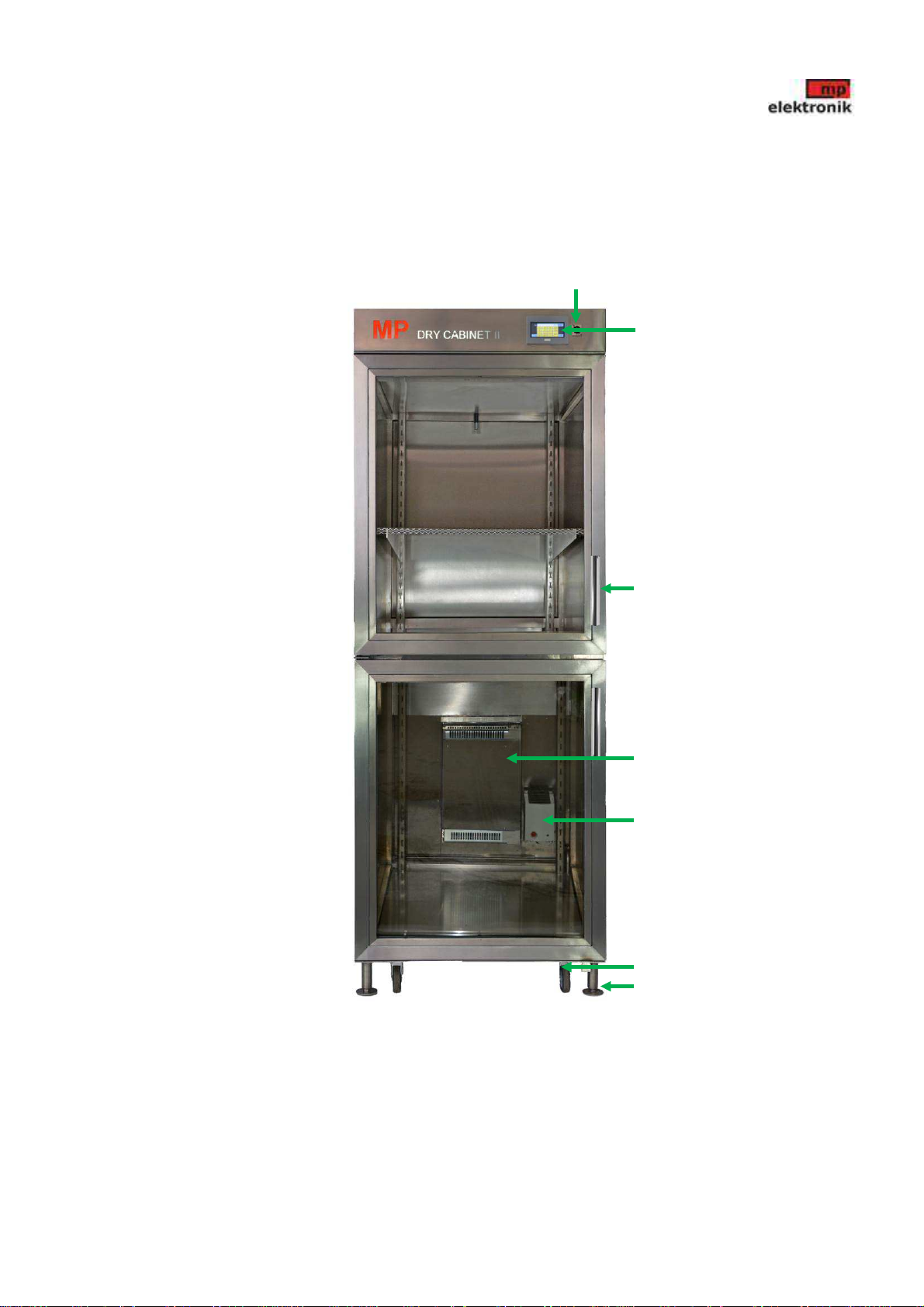
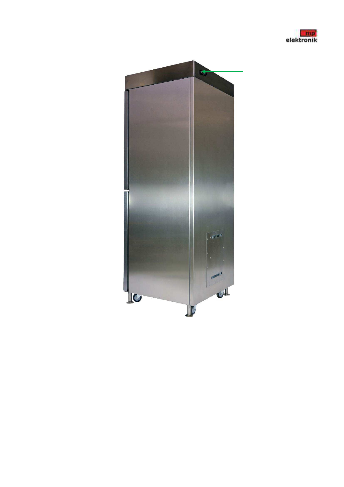
4.1 Construction layout
FRONT VIEW
page 8/22
Door handle
Heater
Drying device
Locking and grounding legs
Travelling wheels
Touch panel
USB
User´s manual
MP DRY CABINET II
REAR SIDE VIEW
page 9/22
Connectors

User´s manual
MP DRY CABINET II
5 Preparation for Use
•
Unpack the device and clean it from the leftovers of the transport material.
•
Check the supply for completeness against the packing bill.
•
Check the intactness of all the parts supplied (mainly the glass ones).
•
Check the control unit, display, indicator lights and connectors for mechanical damage.
!Should you detect any shortcomings during the initial preparation, provide for their repair before the device is
connected to the mains.
5.1 Storage
•
Store MP DRY CABINET device in a place with temperatures from 0 to 45 °C and relative humidity up to 70%.
•
Avoid contact with water, chemical substances or rain.
•
Protect against dust when stored.
5.2 Transport and Assembly
!When handling the device, observe the safety regulations applying to this activity!
!Be extra cautious when handling the heavy device. Its weight is 90, 180, 320 kg according the type!
!IT IS PROHIBITED to expose the device to mechanical shocks and hits.
•
The device is transported assembled and ready to use.
•
When handling the device, never put your hands or other parts of the body under those parts of the device which are
not perfectly mounted or which are moving.
•
Transport the device in a locked position on a common van or truck as means of transportation.
•
During transport, always lock the wheels with the lock mechanism and wedge them with a common wedge for both
front and both rear wheels.
•
Locate the device to the place of operation to allow easy access from all the sides, 150 mm from the wall, as a
minimum.
•
On a place intended for use, secure stability and grounding of device with 4 adjustable legs so that all 4 are firmly
connected to the floor.
!Device while operating cannot stand only on the transport wheels, but on adjustable legs only.
SECURING STABILITY OF THE DEVICE
page 10/22
Locking and grounding legs
Travelling wheels
User´s manual
MP DRY CABINET II
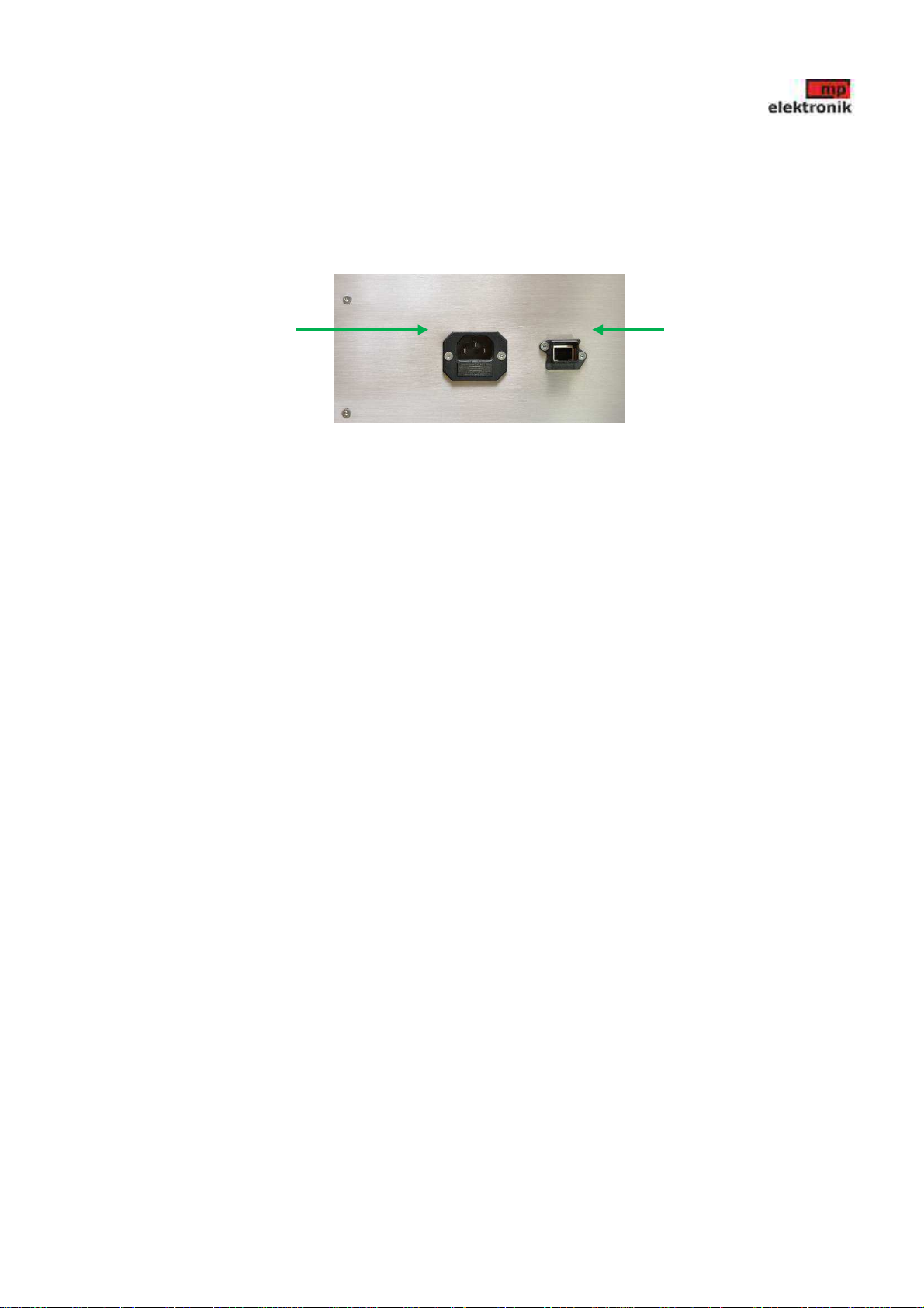
5.3 Power Supply Connection
•
Connect the power supply cable to the mains. (Cu 3 x 1,5 mm)
•
The device is supplied with line voltage 230V 50 Hz via connecting cable. The protective conductor is connected to
the frame of the container in the earthing point. Cable is part of the delivery.
•
The device is ready for the operational check
page 11/22
LANConnector to connect the mains

User´s manual
MP DRY CABINET II
5.4 Operational Check
•
Connect device via cable to the mains.
•
After the start-up of the display, the basic menu of the program will go on and device starts operation.
BASIC MENU
page 12/22

User´s manual
MP DRY CABINET II
6 Instructions to use
All the technological processes are set on the touch panel located in the front of the device.
TOUCH PANEL
6.1 Control Panel Description
After the start-up is displayed basic menu.
BASIC MENU
page 13/22
Touch panel
Current time
and date
Temperature
chart
Button for
setting
Current
values
USB
conector
Humidity
chart
User´s manual
MP DRY CABINET II
To display temperature or humidity in the chart press „chart“
EXAMPLE OF THE CHART
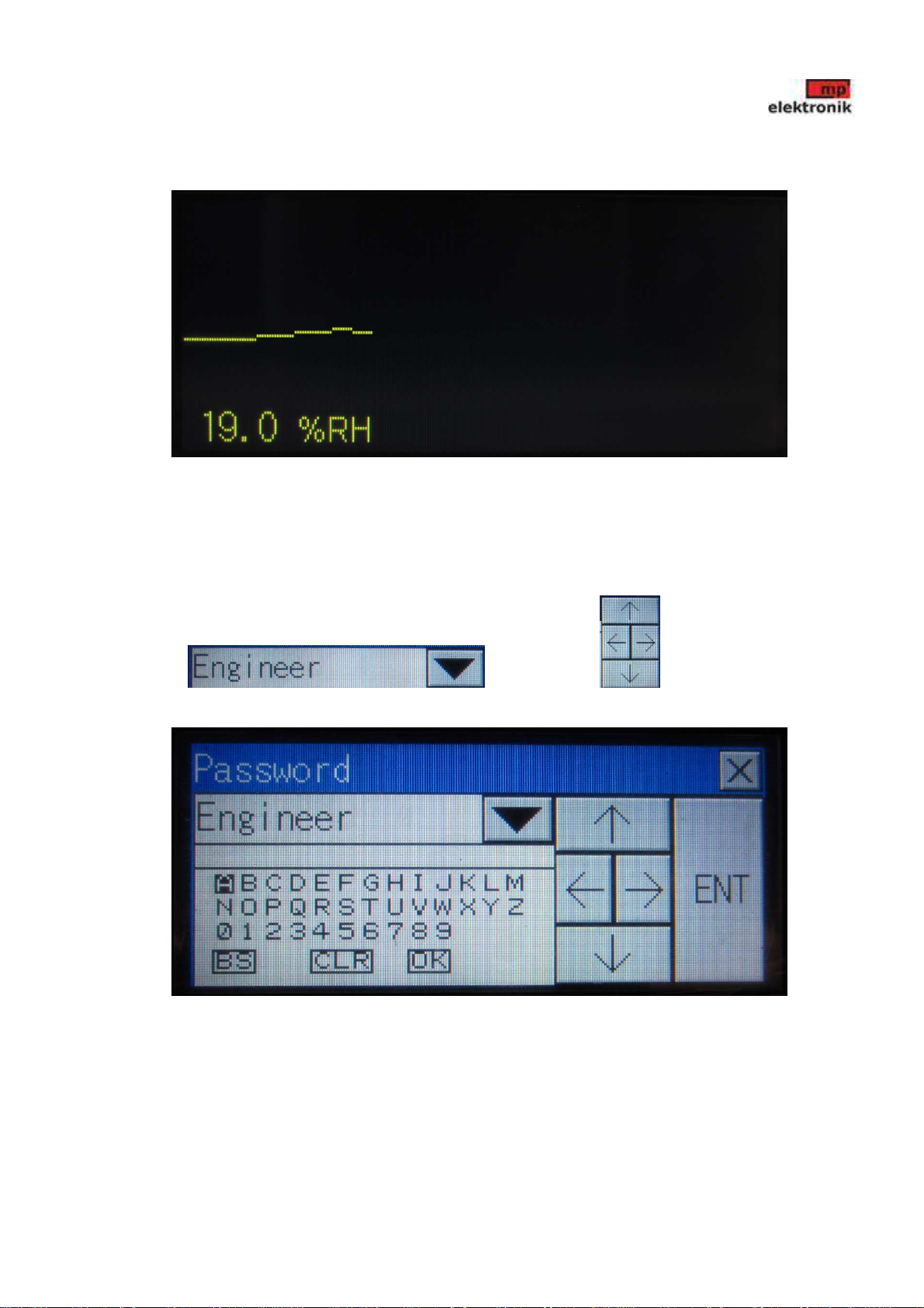
6.2 Log in of the Engineer
The device may be controlled in two access profiles „User“ and „Engineer“. Profile „User“ is set after the start-up of the
device and any parameters can be changed.
To log in as the „Engineer“ press „log.“
Select profile and using arrow insert access password „4856“
and press „Ent“.
ACCESS KEYBOARD
page 14/22
User´s manual
MP DRY CABINET II
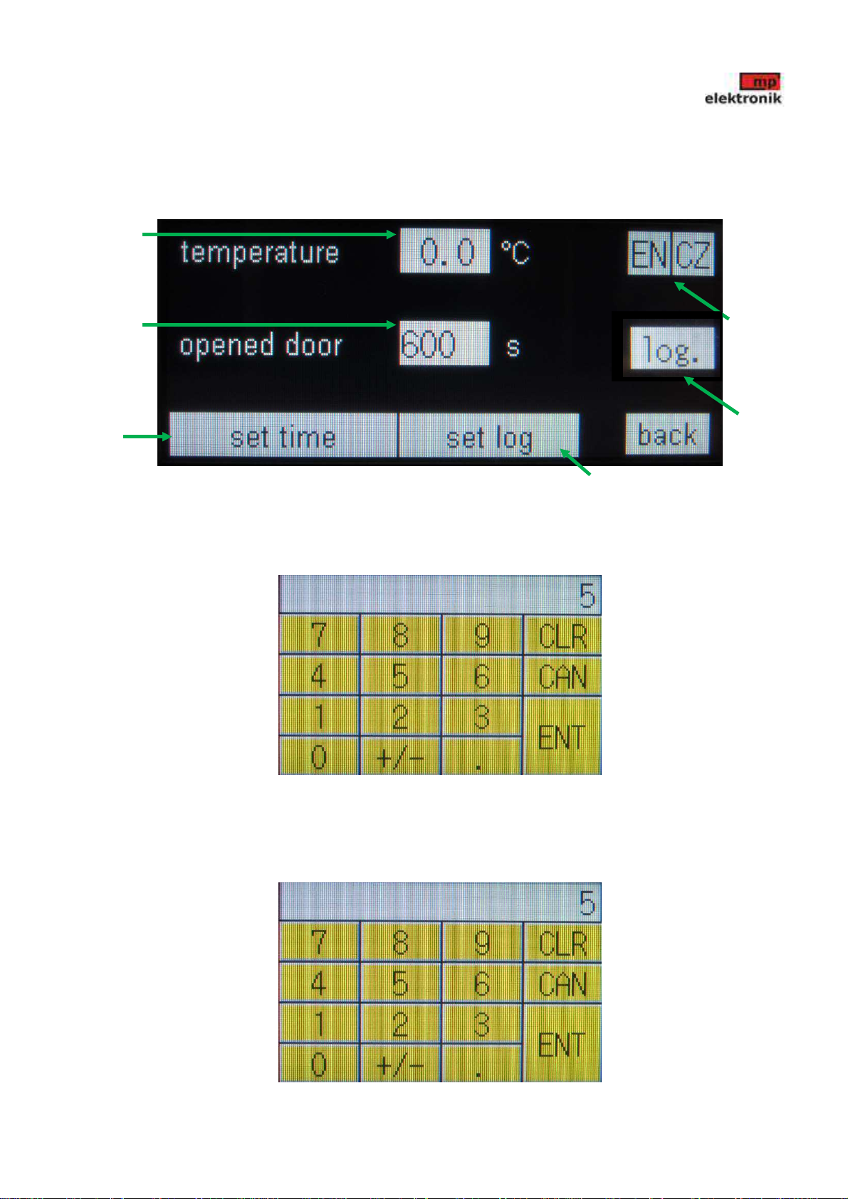
6.3 Setting
For parameters setting press „setting“. Following screen will be displayed.
For temperature setting press active field “temperature”.
Following keyboard will be displayed. Insert required temperature and save by press „ENT“ For correction press „CLR“,
to cancel operation press „CAN“.
KEYBOARD TO INSERT REQUIRED VALUE
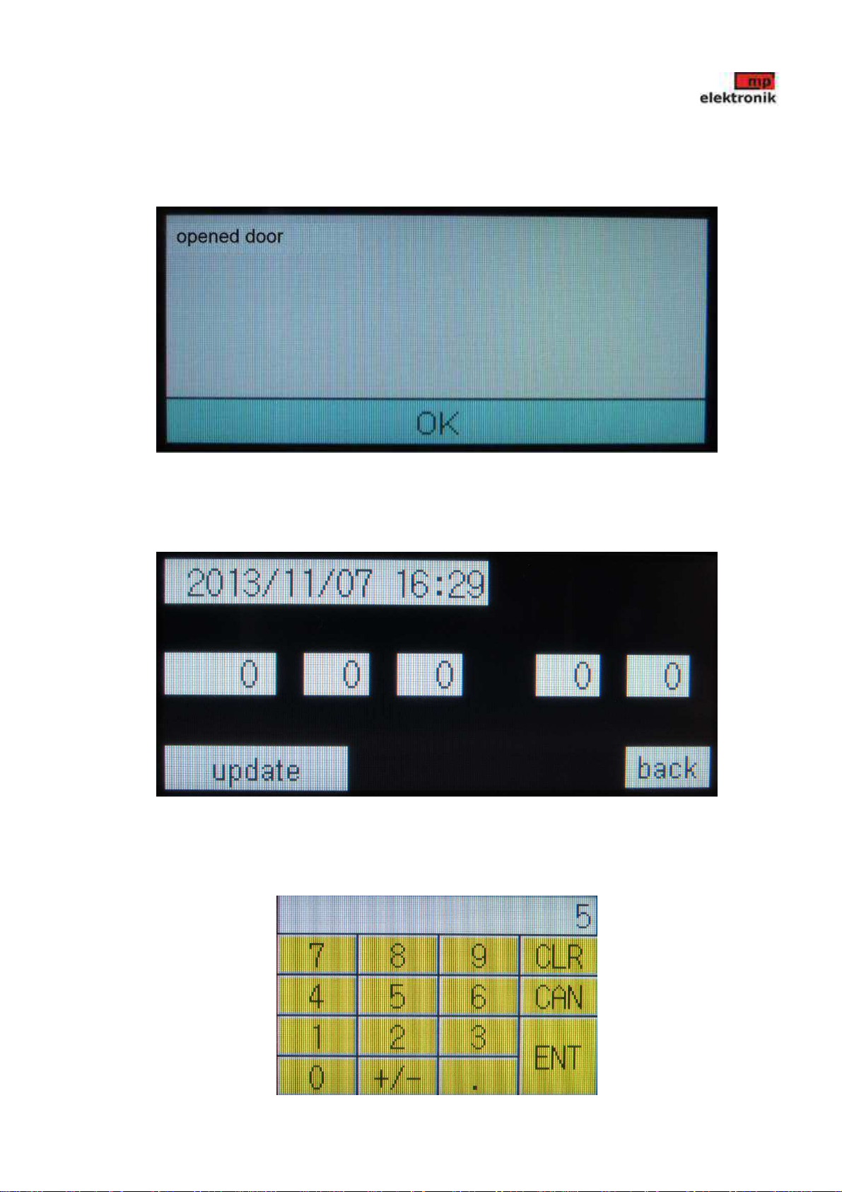
For opened door alarm setting press active field “opened door”.
Following keyboard will be displayed. Insert required temperature and save by press „ENT“ For correction press „CLR“,
to cancel operation press „CAN“.
page 15/22
Time and
date setting
Frequency
of data
saving to
memory
Temperature
setting
Opened door
alarm setting Language
Engineer
log in
User´s manual
MP DRY CABINET II
KEYBOARD TO INSERT REQUIRED VALUE
When exceeded the time allowed for opened door, sweeping sound will go on and following warning will be displayed.
Close door and press „OK“.
For language selection press „EN“ or „CZ“
For time and date setting press „set time“. Following screen will be displayed.
TIME AND DATE SETTING
Set time and date into individual fields. When field pressed, following keyboard will be displayed. Insert required value
and save by press „ENT“ For correction press „CLR“, to cancel operation press „CAN“.
page 16/22

User´s manual
MP DRY CABINET II
KEYBOARD TO INSERT REQUIRED VALUE
page 17/22
User´s manual
MP DRY CABINET II
Press „update“ and press „back“ for return into setting menu.
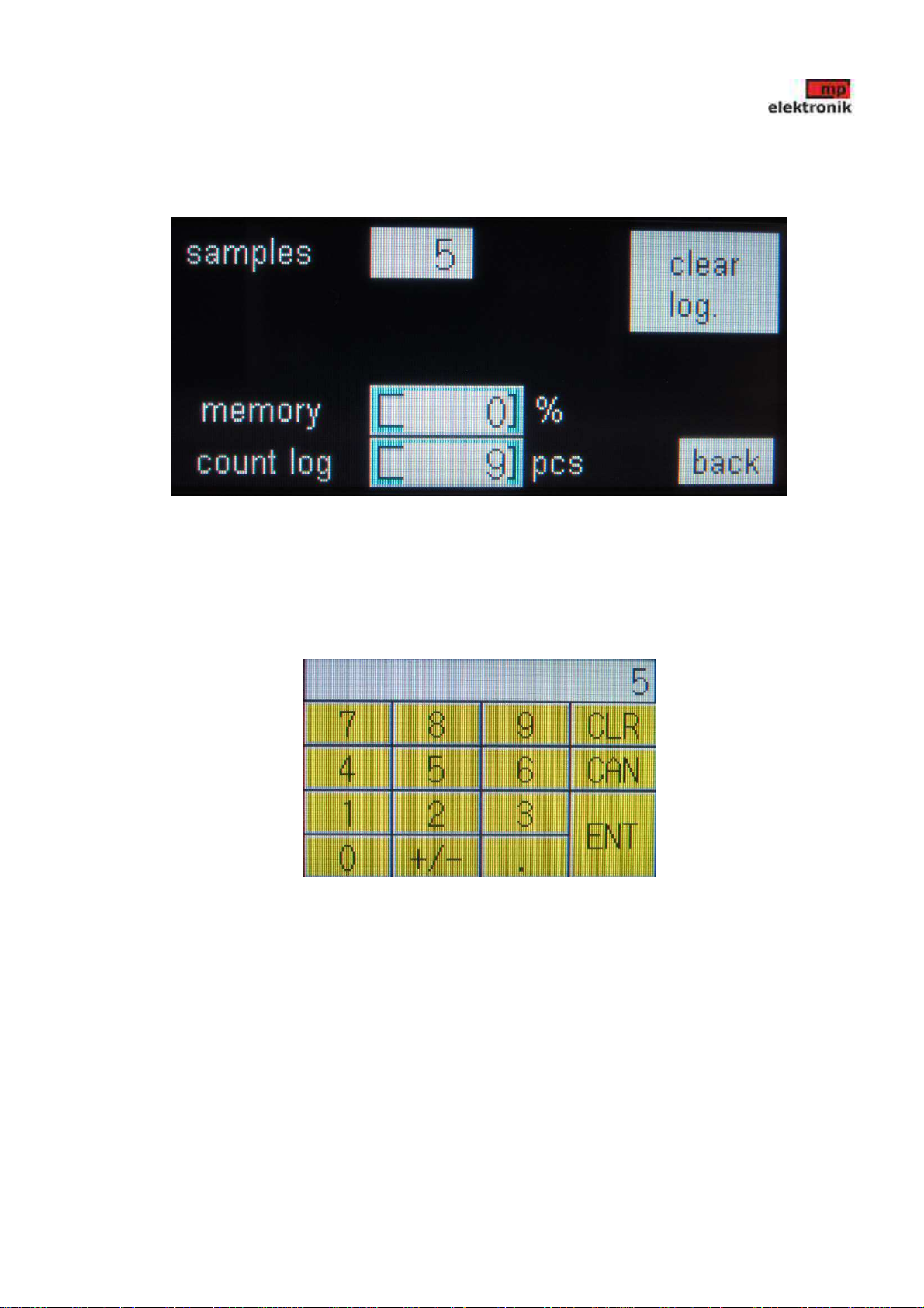
To set sampling frequency of storage pre-set parameters onto memory press „set log“.
PARAMETERS LOG SETTING
Temperature and humidity values are recorded on memory according to the set sampling rate. They are stored in "CSV"
file with the appropriate date and time.
To set the sampling frequency press active field sampling. Following keyboard will be displayed. Values can be set in
range from 0 to 9999 seconds. Insert required value and save by press „ENT“ For correction press „CLR“, to cancel
operation press „CAN“.
KEYBOARD TO INSERT REQUIRED VALUE
Upon reaching 100% occupancy of the memory, stored data will be overwritten from the oldest values. Memory data can
be deleted by pressing the "clear log."
To return to the setup menu, press the "back".
page 18/22
User´s manual
MP DRY CABINET II
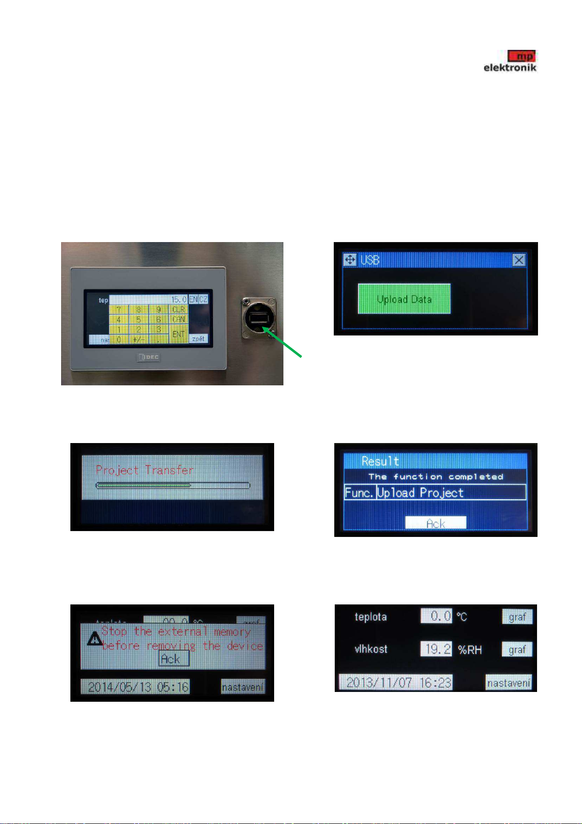
6.4 Saving measurement data on storage device
To copy the measurement data from the internal memory to a PC using a USB storage device (insert it into the connector
located on the front of the device).
In the table for data transfer press "Upload Data". Displayed is copying process "Project transfer". After copying the file,
press the "Ack".
Slide out the memory device and press "Ack" to return to the "Main menu".
Files are stored in a memory device in a directory named "HGDATA01", later in the subdirectory "DATALOG" in files
„log files.csv“ and „door.csv“.
USB stick connection Copy confirmation
Copy progress Copy finnshed
Remove USB Main menu
page 19/22
USB
connector

User´s manual
MP DRY CABINET II
7
page 20/22
Table of contents
Other MP Industrial Equipment manuals


