MPFiltri FZH Series Manual

ATEX 2014/34/UE
& U.K. Regulation S.I. 2016 No. 1107 (as amended)
FZH series
Installation, service and maintenance manual
and safety instructions
intended for use in potentially explosive atmospheres
Manuale di installazione, uso, manutenzione
ed istruzioni di sicurezza
& U.K. Regulation S.I. 2016 No. 1107 (as amended)
destinati all'impiego in zone a rischio di esplosione

ENGLISH
INDEX
Please scan the QR codes to get updated
electronic version of the related document.
FZH040FZH012
2
2
2
3
4
5
5
6
6
7
7
8
10
12
12
13
14
14
14
15
16
17
17
18
18
19
19
20
22
24
24
25
26
26
29
31
31
31
31
30
Page
Page
1. Description
2. General warnings
3. Tools
4. Handling
5. Dimensional drawings
6. Installation
7. Commissioning
8. Standard maintenance
8.1 Filter element replacement
9. Special maintenance
9.1 Clogging indicator (or plug) replacement
9.2 Seals replacement
10. Spare parts list
11. Ordering code
11.1 Filter / Housing / Bowl
11.2 Filter element
12. Instructions for use in explosive atmospheres
12.1 Marking
12.2 Safety instructions for installation in a hazardous area
13. Regulations
14. Troubleshooting
14.1 Misuse of the product
14.2 Clogging indicator alarm
14.3 Leaks of working uid
Stainless steel high pressure lters
1
EN
1. Description
The hydraulic lters are components intended for use in potentially explosive atmospheres to remove the
contaminants from the hydraulic uids used in the hydraulic systems. FZH lters are made of stainless steel to meet
extreme conditions and corrosive environments, with maximum pressure up to700 bar, ow rate up to50 l/min.
2. General warnings
- Before the installation, use or maintenance of the lter carefully read the manual
- The system and the lter are pressurised! Be sure the system is at ambient pressure before starting any activity
- The uid temperature inside the system and the lter can cause injuries to personnel or create a hazardous
environment
- Any activity must be carried out by trained and certied specialists, they must use the correct protective equipment
- Any activity must be carried out using the correct tool
- Any activity must be carried out in accordance with the laws in force in the country where the system is in
operation
- The data shown onto the nameplate must be complete and legible during the whole lter working life
- Connect the lter with an anti-loosening system and regularly check the condition of the connection
- The declared performances and the safety of the product are only guaranteed when MP Filtri original spare parts
are used
- Warranty is only effective if MP Filtri original spare parts are used.
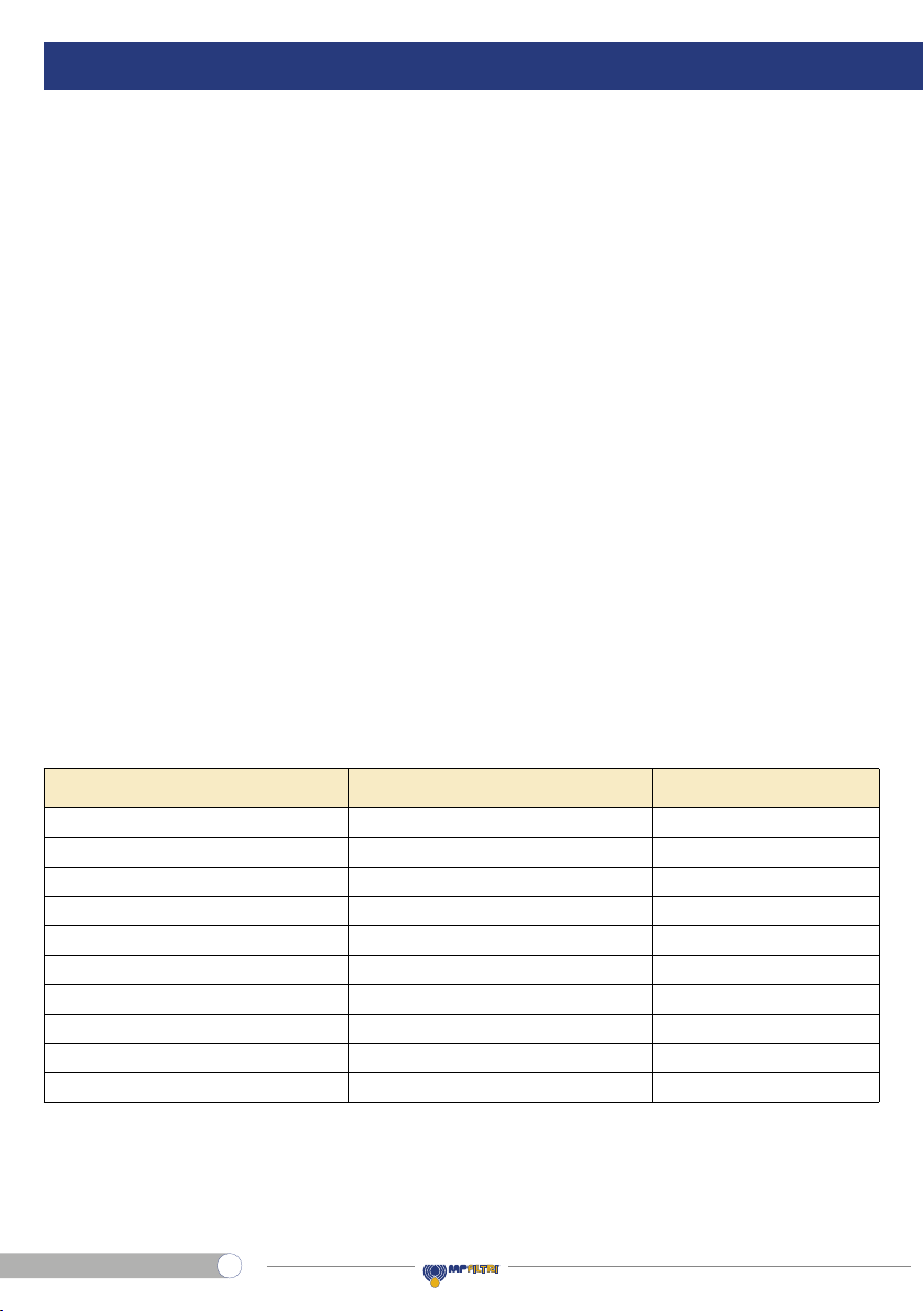
3. Tools
FZH012 TOOL TIGHTENING TORQUE
Differential indicator Wrench A/F 30 110 N∙m
Bowl Wrench A/F 50 45 N∙m
Connection G 1/4 Wrench A/F 19 Max 35 N∙m
Connection 1/4-18 NPT Wrench A/F 14 Max 28 N∙m
Connection 1/2-20 (SAE 5) Wrench A/F 17 Max 28 N∙m
Connection G 3/8 Wrench A/F 22 Max 45 N∙m
Connection 3/8-18 NPT Wrench A/F 19 Max 34 N∙m
Connection 9/16-18 (SAE 6) Wrench A/F 17 Max 34 N∙m
Fastening screws M6 Socket wrench A/F 10 11 N∙m
Fastening screws 1/4-20 UNC Socket wrench A/F 7/16" (11) 12 N∙m
Stainless steel high pressure lters
2
EN
ENGLISH
FZH012
4. Handling
- The unit is shipped in a cardboard box with dimensions depending on the order
- The handling must be carried out in accordance with the laws in force in the country of use of the product
- Handle the product with care, avoid impacts
- Store in a dry and frost-free room
- The unit should be stored in a suitable location away from the production area when not in use.
The unit should be stored with the caps provided on the ports and the bowl’s protective net, if present.
This location should not impede any other production or personnel.
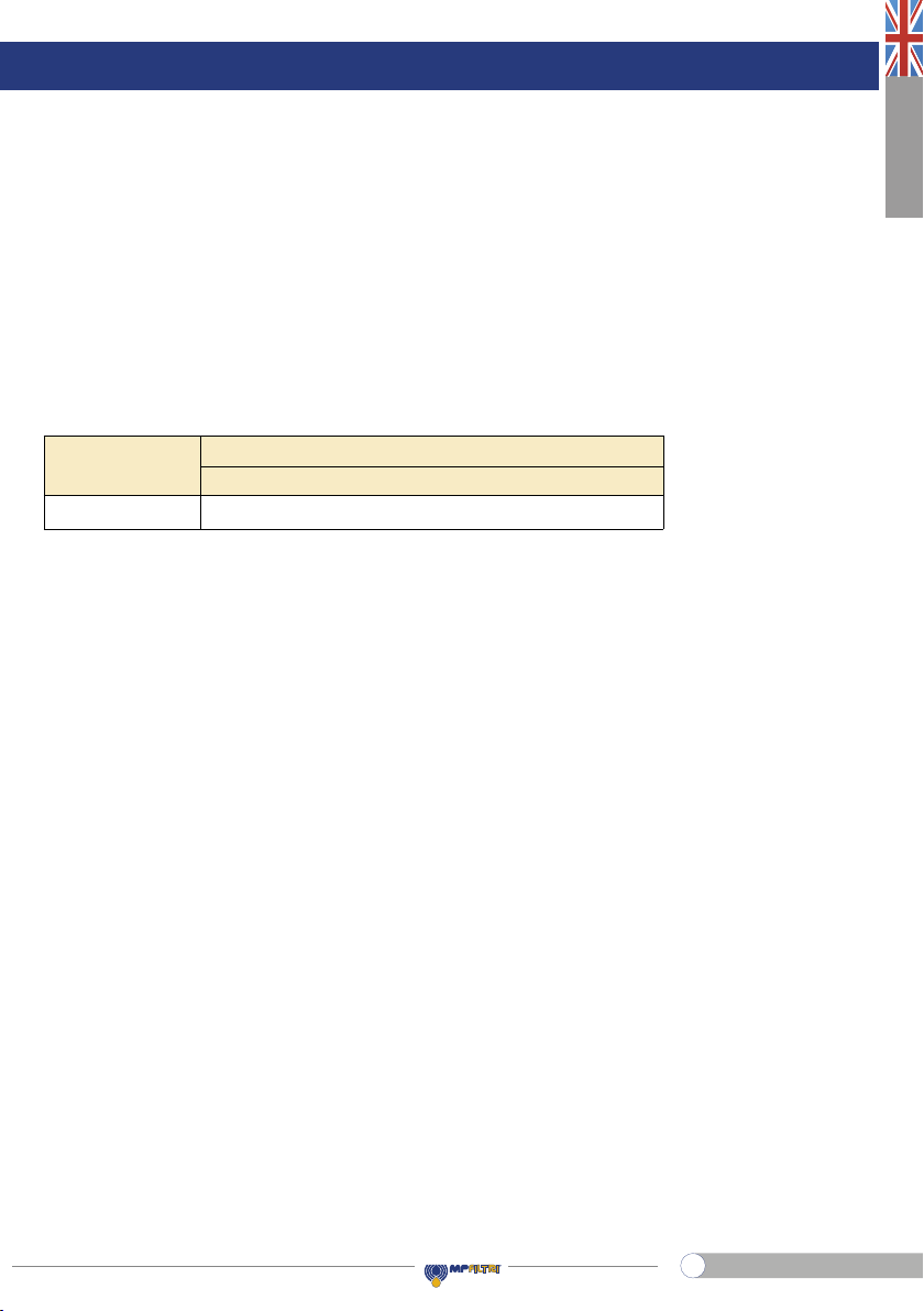
Please refer to the following Weight table:
2.1 3.32.2 2.7
1Length 42 3
FZH012
WEIGHTS [kg]
SERIES
AND SIZE
Stainless steel high pressure lters
3
EN
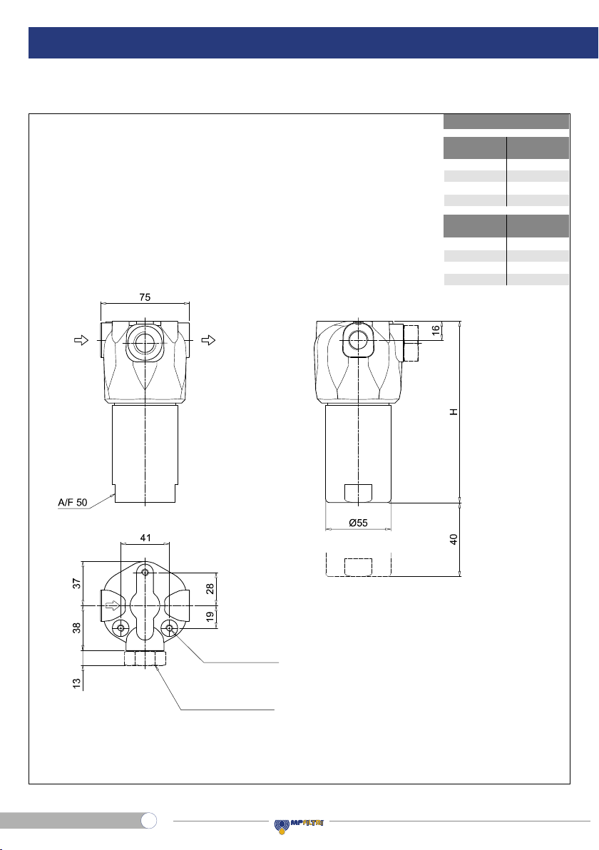
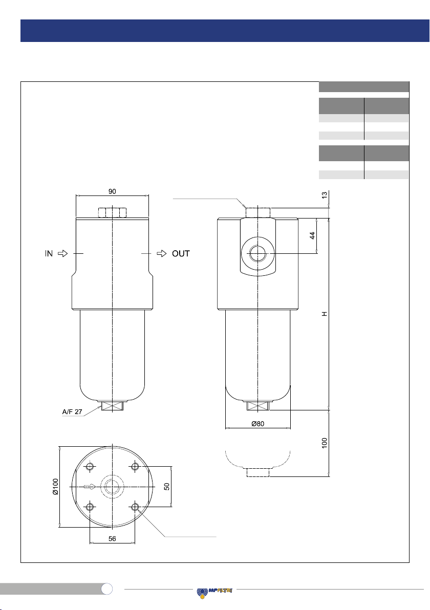
OUTIN
Recommended
clearance space
for maintenance
Connection for
differential indicator
X3 plug not included
R - depth 12 mm
Nr. 3 holes
5. Dimensional drawings
FZH012
H
[mm]
1
2
3
4
93
104
154
204
R
A
B - C
D
E - F
M6
1/4” UNC
M6
1/4” UNC
Connections
Filter
length
Stainless steel high pressure lters
4
EN

ENGLISH
FZH012
6. Installation
- Check that the system working pressure does not exceed the maximum working pressure of the lter.
The maximum working pressure of the lter is shown on the laser marking on the head
- Check that the lter is compatible with the uid used in the system
- Remove the plastic plugs from the inlet, the outlet and the indicator connection
- Check that the correct lter elements are tted into the lter
- Check the ow direction (the ow is indicated byan arrowon the on the head)
- Install the clogging indicator, if required.
In the case of using an electrical clogging indicator, follow the electrical diagram for correct installation
- Fasten the lter to the bracket with the correct bolts. Be sure to t the lter without any tension stress
- Check that there is appropriate clearance for maintenance and the lter elements replacement.
Correct operation is only guaranteed if the lter is installed in a vertical orientation with the lter housing at the top
- Check for a good view of the clogging indicator
- Connect the lter to the hydraulic system, using the appropriate hydraulic ttings.
7. Commissioning
- Switch on the hydraulic system
- Check the lter is free of leaks
- Check the lter for leaks at the maximum working conditions. (Pressure, temperature …)
- Check the lter does not cause excessive pressure drop checking that the indicator does not show the alarm signal.
Clogging indicator
connection
A
A
A
DescriptionItem
Parts identificationParts identification
FZH012
Clogging indicator connection
Stainless steel high pressure lters
5
EN

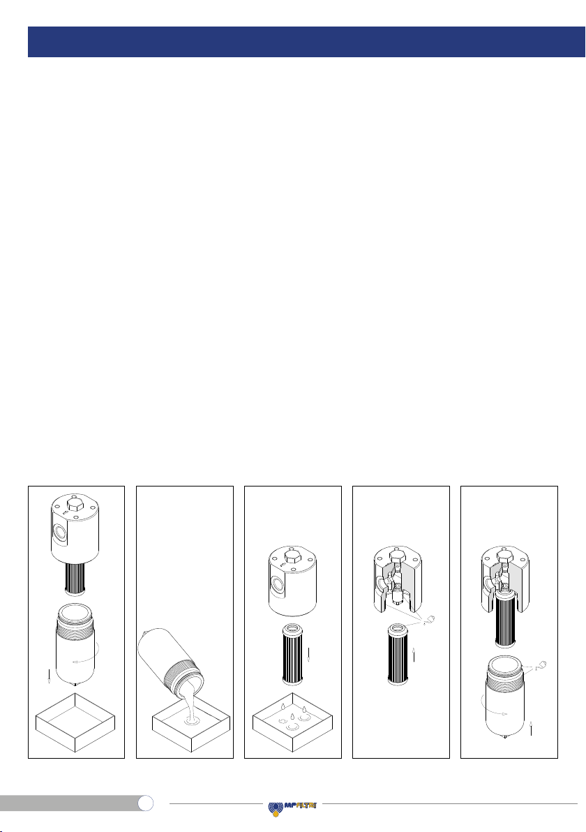
8. Standard maintenance
8.1 FILTER ELEMENT REPLACEMENT
The clogging indicator monitors the conditions of the lter element in the working section of the lter. The alarm signal
shown by the differential indicator during the normal working conditions (Pressure, temperatures …) means that the
lter element needs to be replaced.
- Checktherightsparelterelementisavailable,comparethesparelterelementpartnumberwiththepartnumbershown
on the lter name plate or in the spare parts list
- Switch off the system
- For the disassembly and the assembly of the parts, please refer to the tools table in paragraph 3
- (Fig. 1) Unscrew the lter bowl after placing a vessel to collect the operating uid
- (Fig. 2) Empty the operating uid from the bowl into the collection vessel
- (Fig. 3) Pull the lter element out
- Clean the cavity in the housing, the tap and the bowl. Check them for damage
- Check the condition of the bowl seals and, if necessary, replace them referring to the “Special maintenance”
paragraph
- (Fig.4) Lubricate with the operating uid the lter element O-ring,the housing tap and cavity, then t the lter element
on the tap. Pay attention not to damage the O-ring seal
- (Fig.5) Lubricate the thread and the O-ring of the bowl,then screw the bowl in referring to the tightening torque table
in paragraph 3
- Switch on the system and check the lter for leaks at the maximum working conditions (pressure, temperature…)
- Dispose of the replaced parts and the collected uid in accordance with the laws in force in the country of use of
the product.
Filtro
completo
Smontaggio
contenitore
Svuotamento
contenitore
Smontaggio
elemento
Montaggio
elemento
Montaggio
contenitore
Sost. guarnizioni
elemento+contenitore
Smontaggio
connettore
Smontaggio
corpo indicatore
Montaggio
corpo indicatore
Montaggio
connettore
Sost. guarnizioni
indicatore
Filtro
completo
Smontaggio
contenitore
Svuotamento
contenitore
Smontaggio
elemento
Montaggio
elemento
Montaggio
contenitore
Sost. guarnizioni
elemento+contenitore
Smontaggio
connettore
Smontaggio
corpo indicatore
Montaggio
corpo indicatore
Montaggio
connettore
Sost. guarnizioni
indicatore
Filtro
completo
Smontaggio
contenitore
Svuotamento
contenitore
Smontaggio
elemento
Montaggio
elemento
Montaggio
contenitore
Sost. guarnizioni
elemento+contenitore
Smontaggio
connettore
Smontaggio
corpo indicatore
Montaggio
corpo indicatore
Montaggio
connettore
Sost. guarnizioni
indicatore
Filtro
completo
Smontaggio
contenitore
Svuotamento
contenitore
Smontaggio
elemento
Montaggio
elemento
Montaggio
contenitore
Sost. guarnizioni
elemento+contenitore
Smontaggio
connettore
Smontaggio
corpo indicatore
Montaggio
corpo indicatore
Montaggio
connettore
Sost. guarnizioni
indicatore
Filtro
completo
Smontaggio
contenitore
Svuotamento
contenitore
Smontaggio
elemento
Montaggio
elemento
Montaggio
contenitore
Sost. guarnizioni
elemento+contenitore
Smontaggio
connettore
Smontaggio
corpo indicatore
Montaggio
corpo indicatore
Montaggio
connettore
Sost. guarnizioni
indicatore
g. 1 g. 3 g. 4 g. 5g. 2
Stainless steel high pressure lters
6
EN

ENGLISH
FZH012
9. Special maintenance
9.1 CLOGGING INDICATOR (OR PLUG) REPLACEMENT
- Check the right spare lter element is available, compare the spare lter element part number with the spare parts list
- Switch off the system
- For the disassembly and the assembly of the parts, please refer to the tools table in paragraph 3
- (Fig. 6) Unscrew the indicator body
- (Fig. 7) Lubricate with the operating uid the thread and the O-ring of the indicator body, then screw the indicator body
in referring to the tightening torque table in paragraph 3
- Switch on the system and check the lter for leaks at the maximum working conditions (pressure, temperature…)
- Dispose of the replaced parts and the collected uid in accordance with the laws in force in the country of use of the
product.
g. 6 g. 7
Smontaggio
indicatore
Montaggio
indicatore
Sost. guarnizioni
indicatore
Smontaggio
indicatore
Montaggio
indicatore
Sost. guarnizioni
indicatore
Stainless steel high pressure lters
7
EN

9.2 SEALS REPLACEMENT
- Check the right spare lter element is available, compare the spare lter element part number with the spare parts list
- Switch off the system
- For the disassembly and the assembly of the parts, please refer to the tools table in paragraph 3
- (Fig. 8) Unscrew the lter bowl after placing a vessel to collect the operating uid
- (Fig. 9) Empty the operating uid from the bowl into the collection vessel
- (Fig. 10) Pull the lter element out
- Remove all the seal from the bowl and the lter element, and prepare the spare parts referring to the list in
paragraph 12.
- (Fig. 11) Fit 1°: the anti-extrusion ring and #2: the O-ring in the bowl groove, insert the O-ring in the lter element cap
- Clean the cavity in the housing, the tap and the bowl. Check them for damage
Filtro
completo
Smontaggio
contenitore
Svuotamento
contenitore
Smontaggio
elemento
Montaggio
elemento
Montaggio
contenitore
Sost. guarnizioni
elemento+contenitore
Smontaggio
connettore
Smontaggio
corpo indicatore
Montaggio
corpo indicatore
Montaggio
connettore
Sost. guarnizioni
indicatore
Filtro
completo
Smontaggio
contenitore
Svuotamento
contenitore
Smontaggio
elemento
Montaggio
elemento
Montaggio
contenitore
Sost. guarnizioni
elemento+contenitore
Smontaggio
connettore
Smontaggio
corpo indicatore
Montaggio
corpo indicatore
Montaggio
connettore
Sost. guarnizioni
indicatore
Filtro
completo
Smontaggio
contenitore
Svuotamento
contenitore
Smontaggio
elemento
Montaggio
elemento
Montaggio
contenitore
Sost. guarnizioni
elemento+contenitore
Smontaggio
connettore
Smontaggio
corpo indicatore
Montaggio
corpo indicatore
Montaggio
connettore
Sost. guarnizioni
indicatore
Filtro
completo
Smontaggio
contenitore
Svuotamento
contenitore
Smontaggio
elemento
Montaggio
elemento
Montaggio
contenitore
Sost. guarnizioni
elemento+contenitore
Smontaggio
connettore
Smontaggio
corpo indicatore
Montaggio
corpo indicatore
Montaggio
connettore
Sost. guarnizioni
indicatore
g. 8 g. 10 g. 11g. 9
Stainless steel high pressure lters
8
EN

ENGLISH
FZH012
- (Fig. 12) Lubricate with the operating uid the lter element O-ring, the housing tap and cavity, then t the lter
element on the tap. Pay attention not to damage the O-ring seal
- (Fig. 13) Lubricate the thread and the O-ring of the bowl, then screw the bowl in referring to the tightening torque table
in paragraph 3
- (Fig. 14) Replace the O-rings of the indicator body
- For the mounting/dismounting of the indicator, please refer to the paragraph “Clogging indicator replacement”
above (Fig. 6÷7)
- Switch on the system and check the lter for leaks at the maximum working conditions (pressure, temperature…)
- Dispose of the replaced parts and the collected uid in accordance with the laws in force in the country of use of the
product.
g. 12 g. 13 g. 14
Filtro
completo
Smontaggio
contenitore
Svuotamento
contenitore
Smontaggio
elemento
Montaggio
elemento
Montaggio
contenitore
Sost. guarnizioni
elemento+contenitore
Smontaggio
connettore
Smontaggio
corpo indicatore
Montaggio
corpo indicatore
Montaggio
connettore
Sost. guarnizioni
indicatore
Filtro
completo
Smontaggio
contenitore
Svuotamento
contenitore
Smontaggio
elemento
Montaggio
elemento
Montaggio
contenitore
Sost. guarnizioni
elemento+contenitore
Smontaggio
connettore
Smontaggio
corpo indicatore
Montaggio
corpo indicatore
Montaggio
connettore
Sost. guarnizioni
indicatore
Smontaggio
indicatore
Montaggio
indicatore
Sost. guarnizioni
indicatore
Stainless steel high pressure lters
9
EN
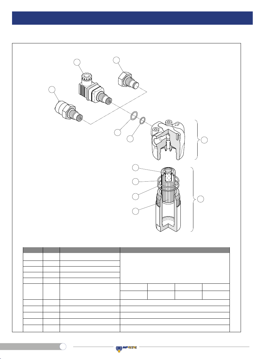
10. Spare parts list
Seals kit
7
Clogging indicator
5 Filter element
4Bowl
3Housing
Complete filter
1
DescriptionItem Designation / ordering codeQ.ty
6
Filter element seal
Bowl seal
Indicator seal
NBR FPM
7b
7a
7c
7d
O-Ring 121 - di = 15,88 - d2= 2,62
Indicator seal
See ordering table
O-Ring 3168 - di = 42,52 - d2= 2,62
O-Ring 2050 - di = 12,42 - d2= 1,78
O-Ring BS908 (01636-221) - di = 16,36 - d2= 2,21 - 90 °Sh A
1
1
1
1
1
1
1
1
1
1
See ordering table
See ordering table
See ordering table
See ordering table
Bowl anti-extrusion ring SR131
1
7e
02050856 02050857
EPDM
02050858
MFQ
02050859
Spare parts list
FZH012
6a
3
4
6b
6c
7a
7d
7e
7b
7c
5
Item Quantity Description Designation / Ordering code
Complete lter
Housing
Bowl assembly
Filter element
Clogging indicator
Filter element seal
Bowl seal
Bowl anti-extrusion ring
Indicator seal
Indicator seal
Seals kit
NBR EPDMFPM MFQ
See “Ordering Code” table
0205085902050856 02050857 02050858
1
1
1
1
1
1
1
1
1
1
1
1
3
4
5
6
7
7a
7b
7c
7d
7e
O-Ring 121 - di = 15.88 - d2= 2.62
O-Ring 3168 - di = 42.52 - d2= 2.62
SR131
O-Ring BS908 (01636-221) - di = 16.36 - d2= 2.21 - 90 °Sh A
O-Ring 2050 - di = 12.42 - d2= 1.78
Stainless steel high pressure lters
10
EN

ENGLISH
FZH012
Stainless steel high pressure lters
11
EN

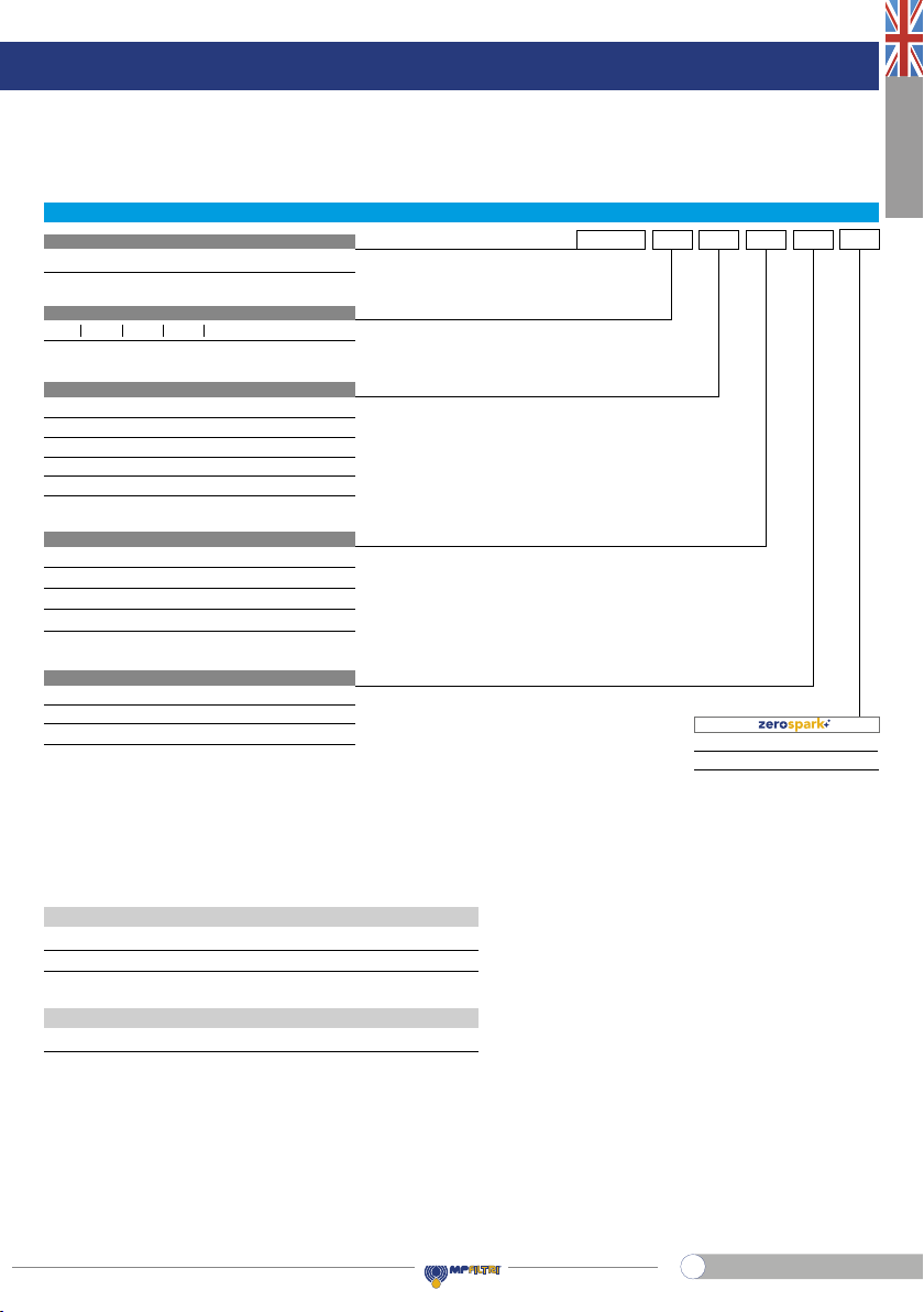
11. Ordering code
11.1 FILTER / HOUSING / BOWL
FILTER / HOUSING / BOWL
Valves
ZVBS
•
•
•
•
•
•
•-
-
-
-
•
Element ∆p
N
H
U
20 bar
210 bar
210 bar, stainless steel lter element
Filtration rating (lter media)
A03
A10
A06
A16
A25
Inorganic microber 3 µm
Inorganic microber 10 µm
Inorganic microber 6 µm
Inorganic microber 16 µm
Inorganic microber 25 µm
Filter Series and size FZH012 F2 U2B B A03
Filter length
1 2 3 4
S
FZH012
B
HZH011
Without bypass
With bypass 6 bar
V
Z
With reverse ow, without bypass
With reverse ow, with bypass 6 bar
Valves
Seals
ANBR
VFPM
E
F
EPDM
MFQ
Connections
A
D
C
F
B
E
G 1/4”
G 3/8”
SAE 5 - 1/2” - 20 UNF
SAE 6 - 9/16” - 18 UNF
1/4” NPT
3/8” NPT
Connection for differential indicator
1
2
Without connection
With connection
FZH012 F 2B B
HZH011 F2 UA03
Filter:
Filter / housing
Bowl assembly
Housing:
Bowl:
Z01 EX
Z01 EX
Z01
Certications
EX Atex certications
Execution
Z01
Zxx
MP Filtri standard
Customized
Stainless steel high pressure lters
12
EN
ENGLISH
FZH012
11.2 FILTER ELEMENT
Example:
HP011 F2 UA03
Element length
Element series and size
HP011
FILTER ELEMENT
Element ∆p
N
H
U
20 bar
210 bar
210 bar, stainless steel lter element
Filtration rating (lter media)
A03
A10
A06
A16
A25
Inorganic microber 3 µm
Inorganic microber 10 µm
Inorganic microber 6 µm
Inorganic microber 16 µm
Inorganic microber 25 µm
1234
Seals
ANBR
VFPM
E
F
EPDM
MFQ
INDICATORS
ADDITIONAL FEATURES
DEZ
DVZ
Electrical differential indicator
Visual differential indicator
X3 Plug
Z01
Execution
Z01
Zxx
MP Filtri standard
Customized
Stainless steel high pressure lters
13
EN

1. Description
The hydraulic lters are components intended for use in potentially explosive atmospheres to remove the contaminants
from the hydraulic uids used in the hydraulic systems. FZH lters are made of stainless steel to meet extreme
conditions and corrosive environments, with maximum pressure up to700 bar, ow rate up to50 l/min.
2. General warnings
- Before the installation, use or maintenance of the lter carefully read the manual
- The system and the lter are pressurised! Be sure the system is at ambient pressure before starting any activity
- The uid temperature inside the system and the lter can cause injuries to personnel or create a hazardous
environment
- Any activity must be carried out by trained and certied specialists, they must use the correct protective equipment
- Any activity must be carried out using the correct tool
- Any activity must be carried out in accordance with the laws in force in the country where the system is in
operation
- The data shown onto the nameplate must be complete and legible during the whole lter working life
- Connect the lter with an anti-loosening system and regularly check the condition of the connection
- The declared performances and the safety of the product are only guaranteed when MP Filtri original spare parts
are used
- Warranty is only effective if MP Filtri original spare parts are used.
3. Tools
FZH040 TOOL TIGHTENING TORQUE
Differential indicator Wrench A/F 30 110 N∙m
Bowl Wrench A/F 50 45 N∙m
Connection G 1/4 Wrench A/F 19 Max 35 N∙m
Connection 1/4-18 NPT Wrench A/F 14 Max 28 N∙m
Connection 1/2-20 (SAE 5) Wrench A/F 17 Max 28 N∙m
Connection G 3/8 Wrench A/F 22 Max 45 N∙m
Connection 3/8-18 NPT Wrench A/F 19 Max 34 N∙m
Connection 9/16-18 (SAE 6) Wrench A/F 17 Max 34 N∙m
Fastening screws M6 Socket wrench A/F 10 11 N∙m
Fastening screws 1/4-20 UNC Socket wrench A/F 7/16" (11) 12 N∙m
Stainless steel high pressure lters
14
EN

ENGLISH
FZH040
Length
5.64.5 5.1
42 3
FZH040
WEIGHTS [kg]
4. Handling
- The unit is shipped in a cardboard box with dimensions depending on the order
- The handling must be carried out in accordance with the laws in force in the country of use of the product
- Handle the product with care, avoid impacts
- Store in a dry and frost-free room
- Theunit shouldbestoredinasuitablelocationawayfromtheproductionareawhennotinuse.Theunitshouldbestored
with the caps provided on the ports and the bowl’s protective net,if present.This location should not impede any other
production or personnel.
Please refer to the following Weight table:
SERIES
AND SIZE
Stainless steel high pressure lters
15
EN
5. Dimensional drawings
FZH040
Filter
length
H
[mm]
2
3
4
204
247
291
Connections R
A
B - C
M10
3/8” UNC
Recommended
clearance space
for maintenance
Connection for
differential indicator
X3 plug not included
R - depth 12 mm
Nr. 4 holes
Stainless steel high pressure lters
16
EN

ENGLISH
FZH040
6. Installation
- Check that the system working pressure does not exceed the maximum working pressure of the lter.
The maximum working pressure of the lter is shown on the laser marking on the head
- Check that the lter is compatible with the uid used in the system
- Remove the plastic plugs from the inlet, the outlet and the indicator connection
- Check that the correct lter elements are tted into the lter
- Check the ow direction (the ow is indicated byan arrowon the on the head).
- Install the clogging indicator, if required.
In the case of using an electrical clogging indicator, follow the electrical diagram for correct installation
- Fasten the lter to the bracket with the correct bolts. Be sure to t the lter without any tension stress
- Check that there is appropriate clearance for maintenance and the lter elements replacement.
Correct operation is only guaranteed if the lter is installed in a vertical orientation with the lter housing at the top
- Check for a good view of the clogging indicator
- Connect the lter to the hydraulic system, using the appropriate hydraulic ttings.
7. Commissioning
- Switch on the hydraulic system
- Check the lter is free of leaks
- Check the lter for leaks at the maximum working conditions. (Pressure, temperature …)
- Check the lter does not cause excessive pressure drop checking that the indicator does not show the alarm
signal.
Clogging indicator
connection
A
A
DescriptionItem
Parts identificationParts identification
FZH040
Clogging indicator connection
A
Stainless steel high pressure lters
17
EN
8. Standard maintenance
8.1 FILTER ELEMENT REPLACEMENT
The clogging indicator monitors the conditions of the lter element in the working section of the lter. The alarm signal
shown by the differential indicator during the normal working conditions (Pressure, temperatures …) means that the
lter element needs to be replaced.
- Checktherightsparelterelementisavailable,comparethesparelterelementpartnumberwiththepartnumbershown
on the lter name plate or in the spare parts list
- Switch off the system
- For the disassembly and the assembly of the parts, please refer to the tools table in paragraph 3
- (Fig. 1) Unscrew the lter bowl after placing a vessel to collect the operating uid
- (Fig. 2) Empty the operating uid from the bowl into the collection vessel
- (Fig. 3) Pull the lter element out
- Clean the cavity in the housing, the tap and the bowl. Check them for damage
- Check the condition of the bowl seals and, if necessary, replace them referring to the “Special maintenance”
paragraph
- (Fig.4) Lubricate with the operating uid the lter element O-ring,the housing tap and cavity, then t the lter element
on the tap. Pay attention not to damage the O-ring seal
- (Fig.5) Lubricate the thread and the O-ring of the bowl,then screw the bowl in referring to the tightening torque table
in paragraph 3
- Switch on the system and check the lter for leaks at the maximum working conditions (pressure, temperature…)
- Dispose of the replaced parts and the collected uid in accordance with the laws in force in the country of use of
the product.
Filtro
completo
Smontaggio
contenitore
Svuotamento
contenitore
Smontaggio
elemento
Montaggio
elemento
Montaggio
contenitore
Smontaggio
connettore
Smontaggio
corpo indicatore
Montaggio
corpo indicatore
Montaggio
connettore
Sost. guarnizioni
indicatore
Sost. guarnizioni
elemento+contenitore
Filtro
completo
Smontaggio
contenitore
Svuotamento
contenitore
Smontaggio
elemento
Montaggio
elemento
Montaggio
contenitore
Smontaggio
connettore
Smontaggio
corpo indicatore
Montaggio
corpo indicatore
Montaggio
connettore
Sost. guarnizioni
indicatore
Sost. guarnizioni
elemento+contenitore
Filtro
completo
Smontaggio
contenitore
Svuotamento
contenitore
Smontaggio
elemento
Montaggio
elemento
Montaggio
contenitore
Smontaggio
connettore
Smontaggio
corpo indicatore
Montaggio
corpo indicatore
Montaggio
connettore
Sost. guarnizioni
indicatore
Sost. guarnizioni
elemento+contenitore
Filtro
completo
Smontaggio
contenitore
Svuotamento
contenitore
Smontaggio
elemento
Montaggio
elemento
Montaggio
contenitore
Smontaggio
connettore
Smontaggio
corpo indicatore
Montaggio
corpo indicatore
Montaggio
connettore
Sost. guarnizioni
indicatore
Sost. guarnizioni
elemento+contenitore
Filtro
completo
Smontaggio
contenitore
Svuotamento
contenitore
Smontaggio
elemento
Montaggio
elemento
Montaggio
contenitore
Smontaggio
connettore
Smontaggio
corpo indicatore
Montaggio
corpo indicatore
Montaggio
connettore
Sost. guarnizioni
indicatore
Sost. guarnizioni
elemento+contenitore
g. 1 g. 3 g. 4 g. 5g. 2
Stainless steel high pressure lters
18
EN
This manual suits for next models
2
Table of contents
Languages:
Other MPFiltri Industrial Equipment manuals


Popular Industrial Equipment manuals by other brands

ABB
ABB Tmax PR232 Getting started

SKF
SKF MonoFlex OI-AL-SR Component Lifecycle Manual

Siemens
Siemens SIMOVERT MASTERDRIVES 6SE70 C.87-2DA0 Series operating instructions

Tescom
Tescom 44-3200 Instructions for use

Dorner
Dorner 3200 Series Installation, maintenance & parts manual

Festo
Festo CPE PRS Series operating instructions

Mayr
Mayr EAS-NC Lastic-Backlash-free Installation and operational instructions

dymax
dymax SD-100 user guide

deconta
deconta smart dec S 50 Original instruction manual

MK Diamond Products
MK Diamond Products MK-Manta III manual

Stahl
Stahl 8162 Series operating instructions

SDX Audio
SDX Audio THERMOBOX quick start guide


