MPFiltri FMM Series Manual
FMM series
ATEX 2014/34/UE
& U.K. Regulation S.I. 2016 No. 1107 (as amended)
Installation, service and maintenance manual
and safety instructions
intended for use in potentially explosive atmospheres
destinati all'impiego in zone a rischio di esplosione
Manuale di installazione, uso, manutenzione
ed istruzioni di sicurezza


ENGLISH
Page
Page
1. Description
2. General warnings
3. Tools
4. Handling
5. Dimensional drawings
6. Installation
7. Commissioning
8. Standard maintenance
8.1 Filter element replacement
9. Special maintenance
9.1 Clogging indicator (or plug) replacement
9.2 Seals replacement
10. Spare parts list
11. Ordering code
11.1 Filter / Housing / Bowl
11.2 Filter element
12. Instructions for use in explosive atmospheres
12.1 Marking
12.2 Safety instructions for installation in a hazardous area
13. Regulations
14. Troubleshooting
14.1 Misuse of the product
14.2 Clogging indicator alarm
14.3 Leaks of working uid
FMM150FMM050
2
2
2
3
4
5
5
6
6
7
7
8
10
12
12
13
14
14
14
15
16
17
17
18
18
19
19
20
22
24
24
25
26
26
29
31
31
31
31
30
INDEX
Please scan the QR codes to get updated
electronic version of the related document.
1
Atex High Pressure lters
EN

1. Description
The hydraulic lters are components intended for use in potentially explosive atmospheres to remove the contaminants
from the hydraulic uids used in the hydraulic systems, maximum pressure up to420bar, ow rate up to150l/min.
2. General warnings
- Before the installation, use or maintenance of the lter carefully read the manual
- The system and the lter are pressurised! Be sure the system is at ambient pressure before starting any activity
- The uid temperature inside the system and the lter can cause injuries to personnel or create a hazardous
environment
- Any activity must be carried out by trained and certied specialists, they must use the correct protective equipment
- Any activity must be carried out using the correct tool
- Any activity must be carried out in accordance with the laws in force in the country where the system is in
operation
- The data shown onto the nameplate must be complete and legible during the whole lter working life
- Connect the lter with an anti-loosening system and regularly check the condition of the connection
- The declared performances and the safety of the product are only guaranteed when MP Filtri original spare parts
are used
- Warranty is only effective if MP Filtri original spare parts are used.
3. Tools
FMM050 TOOLS TIGHTENING TORQUE
Differential indicator Wrench A/F 27/30/32 60 N∙m
Bowl Wrench A/F 30 65 N∙m
Connection M18 x 1.5 Wrench A/F 27 Max 90 N∙m
Connection M22 x 1.5 Wrench A/F 27 Max 145 N∙m
Connection G 1/2 Wrench A/F 27 Max 65 N∙m
Connection 1/2-14 NPT Wrench A/F 24 Max 60 N∙m
Connection 3/4 - 16 (SAE 8) Wrench A/F 22 Max 55 N∙m
Connection G 3/4 Wrench A/F 32 Max 90 N∙m
Connection 3/4-11.5 NPT Wrench A/F 32 Max 100 N∙m
Connection 1 1/16 - 12 (SAE 12) Wrench A/F 32 Max 100 N∙m
Drain plug G 1/4 Allen key A/F 6 20 N∙m
Fastening screws M10 Socket wrench A/F 17 46 N∙m
Fastening screws 3/8-16 UNC Socket wrench A/F 9/16" 40 N∙m
2
Atex High Pressure lters
EN

ENGLISH
FMM050
4. Handling
- The unit is shipped in a cardboard box with dimensions depending on the order
- The handling must be carried out in accordance with the laws in force in the country of use of the product
- Handle the product with care, avoid impacts
- Store in a dry and frost-free room
- The unit should be stored in a suitable location away from the production area when not in use.
The unit should be stored with the caps provided on the ports and the bowl’s protective net, if present.
This location should not impede any other production or personnel.
Please refer to the following Weight table:
3.11 4.36 5.543.48 3.90
1Length 4 52 3
FMM050
WEIGHTS [kg]
SERIES
AND SIZE
3
Atex High Pressure lters
EN
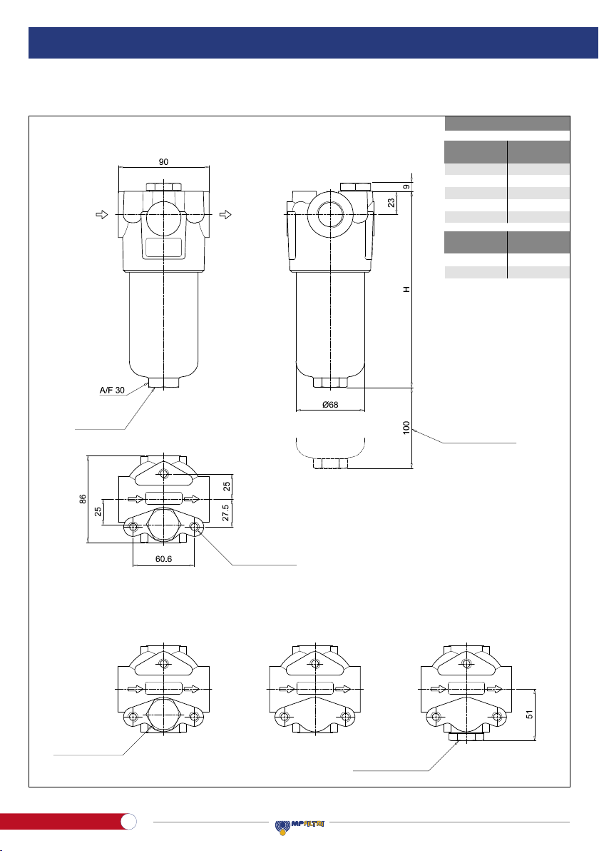
5. Dimensional drawings
FMM050
Filter
length H
[mm]
1
2
3
4
5
158
195
237
285
407
Connections R
A-B-C-D
E-F-G-H
M10
3/8” UNC
OUTIN
Execution P01 Execution P02 Execution P03
Connection for
differential indicator
T2 plug Connection for
differential indicator
T2 plug
Recommended
clearance space
for maintenance
R - depth 12 mm
Nr. 3 holes
Drain plug
only length 5
4
Atex High Pressure lters
EN
ENGLISH
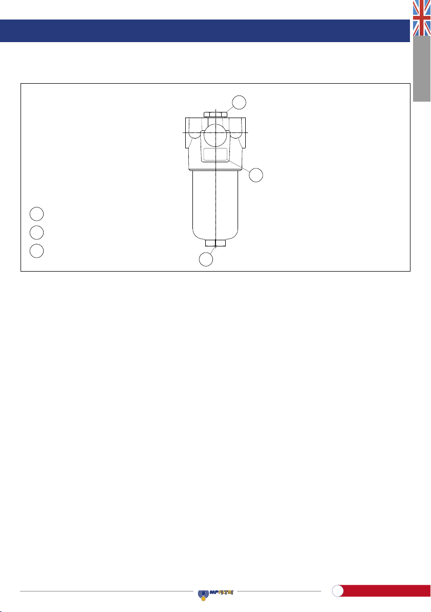
Parts identification
FMM050
Clogging indicator connection
Identification plate
Drain plug
B
A
DescriptionItem
D
A
B
D
FMM050
6. Installation
- Check that the system working pressure does not exceed the maximum working pressure of the lter.
The maximum working pressure of the lter is shown on the identication plate
- Check that the lter is compatible with the uid used in the system
- Remove the plastic plugs from the inlet, the outlet and the indicator connection
- Check that the correct lter elements are tted into the lter
- Check the ow direction (the ow is indicated bytwo arrows on the head)
- Install the clogging indicator, if required.
In the case of using an electrical clogging indicator, follow the electrical diagram for correct installation
- Fasten the lter to the bracket with the correct bolts. Be sure to t the lter without any tension stress
- Check that there is appropriate clearance for maintenance and the lter elements replacement.
Correct operation is only guaranteed if the lter is installed in a vertical orientation with the lter housing at the top
- Check for a good view of the clogging indicator
- Connect the lter to the hydraulic system, using the appropriate hydraulic ttings.
7. Commissioning
- Switch on the hydraulic system
- Check the lter is free of leaks
- Check the lter for leaks at the maximum working conditions. (Pressure, temperature …)
- Check the lter does not cause excessive pressure drop checking that the indicator does not show the alarm signal.
Clogging indicator
connection
Identication plate
Drain plug
A
B
D
A
B
D
5
Atex High Pressure lters
EN

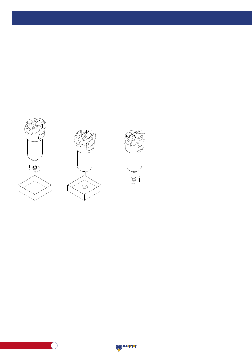
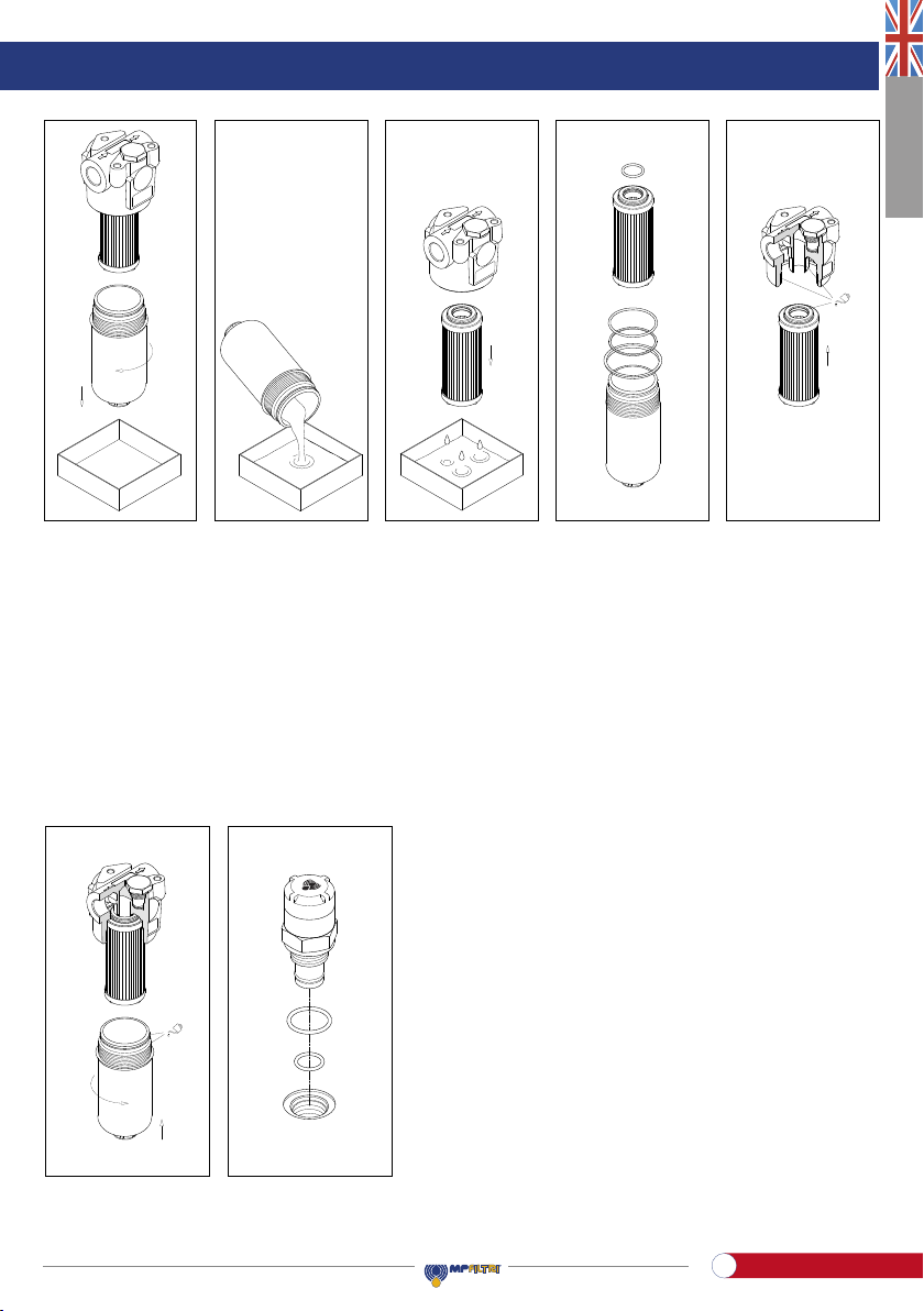
8. Standard maintenance
8.1 FILTER ELEMENT REPLACEMENT
The clogging indicator monitors the conditions of the lter element.The alarm signal shown by the differential indicator
during the normal working conditions (Pressure, temperatures …) means that the lter element needs to be replaced.
- Check the right spare lter element is available, compare the spare lter element part number with the part number
shown on the lter name plate or in the spare parts list
- Switch off the system
- For the disassembly and the assembly of the parts, please refer to the tools table in paragraph 3
- (Fig. 1) If provided, unscrew the drain plug after placing a vessel to collect the operating uid
- (Fig. 2) Drain the operating uid from the bottom of the bowl into the collection vessel
- (Fig. 3) Screw the drain plug in referring to the tightening torque table in paragraph 3
- (Fig. 4) If no drain plug is provided, unscrew the lter bowl after placing a vessel to collect the operating uid
- (Fig. 5) Empty the operating uid from the bowl into the collection vessel
- (Fig. 6) Pull the lter element out. Clean the cavity in the housing, the tap and the bowl. Check them for damage
- Check the condition of the bowl seals and, if necessary, replace them referring to the “Special maintenance”
paragraph
- (Fig. 7) Lubricate with the operating uid the lter element O-ring, the housing tap and cavity, then t the lter
element on the tap. Pay attention not to damage the O-ring seal
- (Fig. 8) Lubricate the thread and the O-ring of the bowl, then screw the bowl in referring to the tightening torque
table in paragraph 3
- Switch on the system and check the lter for leaks at the maximum working conditions (pressure, temperature…)
- Dispose of the replaced parts and the collected uid in accordance with the laws in force in the country of use
of the product.
Filtro
completo
Smontaggio
contenitore
Svuotamento
contenitore
Smontaggio
elemento
Montaggio
elemento
Montaggio
contenitore
Smontaggio
connettore
Smontaggio
corpo indicatore
Montaggio
corpo indicatore
Montaggio
connettore
Sost. guarnizioni
elemento+contenitore
Sost. guarnizioni
indicatore
Smontaggio
tappo di drenaggio
Drenaggio
olio filtro
Montaggio
tappo di drenaggio
g. 1 g. 3g. 2
6
Atex High Pressure lters
EN

ENGLISH
FMM050
9. Special maintenance
9.1 CLOGGING INDICATOR (OR PLUG) REPLACEMENT
- Check the right spare lter element is available, compare the spare lter element part number with the part number
shown on the lter name plate or in the spare parts list
- Switch off the system
- For the disassembly and the assembly of the parts, please refer to the tools table in paragraph 3
- (Fig. 9) Unscrew the indicator body
- (Fig.10) Lubricate with the operating uid the thread and the O-ring of the indicator body,then screw the indicator body
in referring to the tightening torque table in paragraph 3
- Switch on the system and check the lter for leaks at the maximum working conditions (pressure, temperature…)
- Dispose of the replaced parts in accordance with the laws in force in the country of use of the product.
Filtro
completo
Smontaggio
contenitore
Svuotamento
contenitore
Smontaggio
elemento
Montaggio
elemento
Montaggio
contenitore
Smontaggio
connettore
Smontaggio
corpo indicatore
Montaggio
corpo indicatore
Montaggio
connettore
Sost. guarnizioni
elemento+contenitore
Sost. guarnizioni
indicatore
Smontaggio
tappo di drenaggio
Drenaggio
olio filtro
Montaggio
tappo di drenaggio
g. 4 g. 6 g. 7 g. 8g. 5
g. 9 g. 10
Smontaggio
indicatore
Montaggio
indicatore
Sost. guarnizioni
indicatore
Smontaggio
indicatore
Montaggio
indicatore
Sost. guarnizioni
indicatore
7
Atex High Pressure lters
EN
9.2 SEALS REPLACEMENT
- Check the availability of the right spare parts by comparing the part numbers shown on them with that shown
on the lter name plate or spare parts list.
- Switch off the system
- For the disassembly and the assembly of the parts, please refer to the tools table in paragraph 3
- (Fig. 11) If provided, unscrew the drain plug after placing a vessel to collect the operating uid
- (Fig. 12) Drain the operating uid from the bottom of the bowl into the collection vessel
- (Fig. 13) Screw the drain plug in referring to the tightening torque table in paragraph 3
- (Fig. 14) If no drain plug is provided, unscrew the lter bowl after placing a vessel to collect the operating uid
- (Fig. 15) Empty the operating uid from the bowl into the collection vessel
- (Fig. 16) Pull the lter element out. Remove all the seal from the bowl and the lter element and prepare the
spare parts referring to the list in paragraph 12
- Clean the cavity in the housing, the tap and the bowl. Check them for damage
- (Fig. 17) Fit 1°: the anti-extrusion ring and 2°: the O-ring in the bowl groove, insert the O-ring in the lter element cap
- (Fig. 18) Lubricate with the operating uid the lter element O-ring, the housing tap and cavity, then t the lter
element on the tap. Pay attention not to damage the O-ring seal
g. 11 g. 13g. 12
Filtro
completo
Smontaggio
contenitore
Svuotamento
contenitore
Smontaggio
elemento
Montaggio
elemento
Montaggio
contenitore
Smontaggio
connettore
Smontaggio
corpo indicatore
Montaggio
corpo indicatore
Montaggio
connettore
Sost. guarnizioni
elemento+contenitore
Sost. guarnizioni
indicatore
Smontaggio
tappo di drenaggio
Drenaggio
olio filtro
Montaggio
tappo di drenaggio
8
Atex High Pressure lters
EN
ENGLISH
FMM050
- (Fig. 19) Lubricate the thread and the O-ring of the bowl, then screw the bowl in referring to the tightening torque
table in paragraph 3
- (Fig. 20) Replace the O-rings of the indicator body
- For the mounting/dismounting of the indicator, please refer to the paragraph “Clogging indicator replacement”
above (Fig. 9÷10)
- Switch on the system and check the lter for leaks at the maximum working conditions (pressure, temperature…)
- Dispose of the replaced parts and the collected uid in accordance with the laws in force in the country of use of
the product.
g. 19 g. 20
g. 14 g. 16 g. 17 g. 18g. 15
Filtro
completo
Smontaggio
contenitore
Svuotamento
contenitore
Smontaggio
elemento
Montaggio
elemento
Montaggio
contenitore
Smontaggio
connettore
Smontaggio
corpo indicatore
Montaggio
corpo indicatore
Montaggio
connettore
Sost. guarnizioni
elemento+contenitore
Sost. guarnizioni
indicatore
Smontaggio
tappo di drenaggio
Drenaggio
olio filtro
Montaggio
tappo di drenaggio
Smontaggio
indicatore
Montaggio
indicatore
Sost. guarnizioni
indicatore
9
Atex High Pressure lters
EN
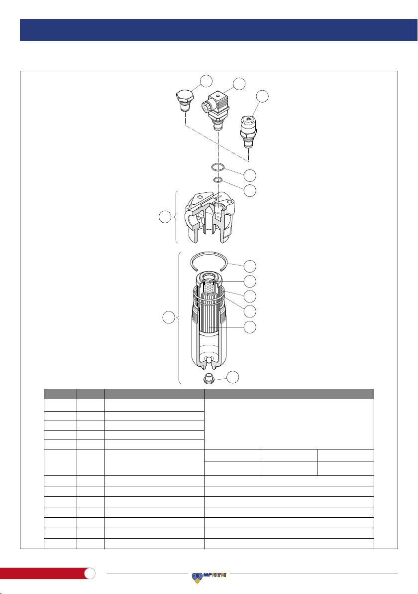
10. Spare parts list
Seals kit
7
Clogging indicator
5 Filter element
4Bowl
3Housing
Complete filter
1
DescriptionItem Designation / ordering codeQ.ty
6
Filter element seal
Bowl seal
Indicator seal
02050314
NBR FPM
02050315
7b
7a
7c
EPDM
02050612
7d
O-Ring 3093 - di = 23,47 - d2= 2,62
Indicator seal
See ordering table
O-Ring 3225 - di = 56,82 - d2= 2,622
O-Ring 2050 - di = 12,42 - d2= 1,78
ORM 0210-20 - di = 21,00 - d2= 2,00
1
1
1
1
1
1
1
1
1
1
See ordering table
See ordering table
See ordering table
See ordering table
7i Drain plug DIN 908-ST-G1/4-A + seal DIN EN 3869
1
Bowl anti-extrusion ring SR139
1
7e
7k Head seal
1Private dimensions
Spare parts list
FMM050
6c
6b
6a
3
4
7a
7b
5
7c
7i
7k
7d
7e
6a
3
4
6b
6c
7a
7k
7i
7d
7e
7b
7c
5
Item Quantity Description Designation / Ordering code
Complete lter
Housing
Bowl Assembly
Filter element
Clogging indicator
Filter element seal
Bowl seal
Bowl anti-extrusion ring
Indicator seal
Indicator seal
Drain plug
Head seal
Seals kit
NBR FPM EPDM
See “Ordering Code” table
0205061202050314 02050315
O-Ring 3093 - di = 23.47 - d2= 2.62
O-Ring 3225 - di = 56.82 - d2= 2.62
SR139
ORM 0210-20 - di = 21.00 - d2= 2.00
O-Ring 2050 - di = 12.42 - d2= 1.78
DIN 908-ST-G1/4-A + seal DIN EN 3869
Private dimensions
1
1
1
1
1
1
1
1
1
1
1
1
1
1
3
4
5
6
7
7a
7b
7c
7d
7e
7i
7k
10
Atex High Pressure lters
EN

ENGLISH
FMM050
11
Atex High Pressure lters
EN

FILTER / HOUSING / BOWL
Filtration rating (lter media)
A03
A10
A06
A16
A25
Inorganic microber 3 µm
Inorganic microber 10 µm
Inorganic microber 6 µm
Inorganic microber 16 µm
Inorganic microber 25 µm
Filter Series and size
Filter length
FMM050
HPB050
11. Ordering code
11.1 FILTER / HOUSING / BOWL
Filter:
Filter / housing
Bowl assembly
Housing:
Bowl:
Valves
Seals
Connections
ANBR
V
E
FPM
EPDM
M25 Wire mesh 25 µm
A
D
C
B
F
H
E
G
M22x1.5 - ISO 6149
G 1/2”
G 3/4”
3/4” NPT
SAE 12 - 1 1/16” - 12 UN
SAE 8 - 3/4” - 16 UNF
1/2” NPT
M18x1.5 - ISO 6149
S
B
T
Without bypass
With bypass 6 bar
With check valve, without bypass
DWith check valve, with bypass 6 bar
FMM050 A3 NB G A10
FMM050 AB G
HPB050 A3 NA10
Z01 EX
Z01 EX
Z01
51 2 3 4
Element ∆p
Valves
DTBS
• •
--
- -
--
-
-
•
•N
R
S
20 bar
20 bar
210 bar
Z01
Z02
Z03
Zxx
Upper connection for clogging indicator
Without connection for clogging indicator
Frontal connection for clogging indicator
Customized
Certications
EX Atex certications
Execution
12
Atex High Pressure lters
EN

ENGLISH
FMM050
Example:
Element length
Element series and size
FILTER ELEMENT
Element ∆p
Filtration rating (lter media)
A03
A10
A06
A16
A25
Inorganic microber 3 µm
Inorganic microber 10 µm
Inorganic microber 6 µm
Inorganic microber 16 µm
Inorganic microber 25 µm
Seals
ANBR
VFPM
EEPDM
11.2 FILTER ELEMENT
51 2 3 4
A3 NA10 Z01
HP050
M25 Rete metallica 25 µm
HP050
N
R
S
20 bar
20 bar
210 bar
INDICATORS
DVA Visual differential indicator
DVM Visual differential indicator
DEH Hazardous area electronic differential indicator
Execution
Z01
Zxx
MP Filtri standard
Customized
13
Atex High Pressure lters
EN

1. Description
The hydraulic lters are components intended for use in potentially explosive atmospheres to remove the contaminants
from the hydraulic uids used in the hydraulic systems, maximum pressure up to420bar, ow rate up to300l/min.
2. General warnings
- Before the installation, use or maintenance of the lter carefully read the manual
- The system and the lter are pressurised! Be sure the system is at ambient pressure before starting any activity
- The uid temperature inside the system and the lter can cause injuries to personnel or create a hazardous
environment
- Any activity must be carried out by trained and certied specialists, they must use the correct protective equipment
- Any activity must be carried out using the correct tool
- Any activity must be carried out in accordance with the laws in force in the country where the system is in
operation
- The data shown onto the nameplate must be complete and legible during the whole lter working life
- Connect the lter with an anti-loosening system and regularly check the condition of the connection
- The declared performances and the safety of the product are only guaranteed when MP Filtri original spare parts
are used
- Warranty is only effective if MP Filtri original spare parts are used.
3. Tools
FMM150 TOOLS TIGHTENING TORQUE
Differential indicator Wrench A/F 27/30/32 60 N∙m
Bowl Wrench A/F 30 70 N∙m
Connection G 1 Wrench A/F 41 Max 150 N∙m
Connection 1 - 11.5 NPT Wrench A/F 41 Max 150 N∙m
Connection 1 5/16 - 12 (SAE 16) Wrench A/F 41 Max 150 N∙m
Connection G 1 1/4 Wrench A/F 50 Max 240 N∙m
Connection 1 1/4 - 11.5 NPT Wrench A/F 46 Max 190 N∙m
Connection 1 5/8 - 12 (SAE 20) Wrench A/F 1 7/8” Max 290 N∙m
Fastening screws M10 Socket wrench A/F 17 46 N∙m
Fastening screws 3/8 - 16 UNC Socket wrench A/F 9/16" 40 N∙m
14
Atex High Pressure lters
EN

ENGLISH
FMM150
4. Handling
- The unit is shipped in a cardboard box with dimensions depending on the order
- The handling must be carried out in accordance with the laws in force in the country of use of the product
- Handle the product with care, avoid impacts
- Store in a dry and frost-free room
- The unit should be stored in a suitable location away from the production area when not in use.
The unit should be stored with the caps provided on the ports and the bowl’s protective net, if present.
This location should not impede any other production or personnel.
Please refer to the following Weight table:
1Length 2 3
FMM150
WEIGHTS [kg]
7.50 9.50 10.90
SERIES
AND SIZE
15
Atex High Pressure lters
EN

5. Dimensional drawings
Ø88
OUTIN
Ø88
FMM150
Filter
length H
[mm]
1
2
3
230
340
415
Connections R
C-D
E-F-G-H
M10
3/8” UNC
Connection for
differential indicator
T2 plug not included
Connection for
differential indicator
T2 plug not included
Recommended
clearance space
for maintenance
R - depth 12 mm
Nr. 4 holes
Version 1 Version 2 Version 3
16
Atex High Pressure lters
EN
ENGLISH
FMM150
6. Installation
- Check that the system working pressure does not exceed the maximum working pressure of the lter.
The maximum working pressure of the lter is shown on the identication plate
- Check that the lter is compatible with the uid used in the system
- Remove the plastic plugs from the inlet, the outlet and the indicator connection
- Check that the correct lter elements are tted into the lter
- Check the ow direction (the ow is indicated by an arrow on the head)
- Install the clogging indicator, if required.
In the case of using an electrical clogging indicator, follow the electrical diagram for correct installation
- Fasten the lter to the bracket with the correct bolts. Be sure to t the lter without any tension stress
- Check that there is appropriate clearance for maintenance and the lter elements replacement.
Correct operation is only guaranteed if the lter is installed in a vertical orientation with the lter housing at the top
- Check for a good view of the clogging indicator
- Connect the lter to the hydraulic system, using the appropriate hydraulic ttings.
7. Commissioning
- Switch on the hydraulic system
- Check the lter is free of leaks
- Check the lter for leaks at the maximum working conditions. (Pressure, temperature …)
- Check the lter does not cause excessive pressure drop checking that the indicator does not show the alarm signal.
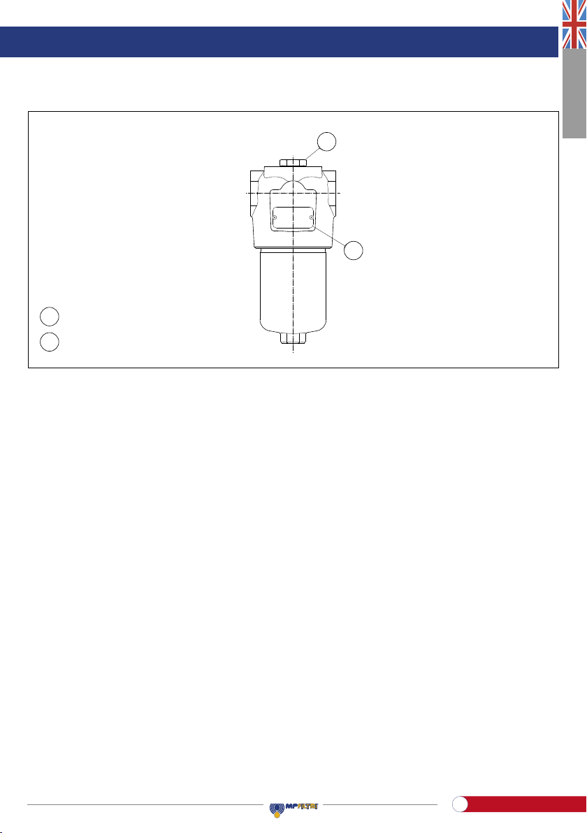
Clogging indicator
connection
Identication plate
A
B
B
A
DescriptionItem
Parts identification
FMM150
Clogging indicator connection
Identification plate
A
BB
A
17
Atex High Pressure lters
EN

Filtro
completo
Smontaggio
contenitore
Svuotamento
contenitore
Smontaggio
elemento
Montaggio
elemento
Montaggio
contenitore
Smontaggio
connettore
Smontaggio
corpo indicatore
Montaggio
corpo indicatore
Montaggio
connettore
Sost. guarnizioni
indicatore
Sost. guarnizioni
elemento+contenitore
Filtro
completo
Smontaggio
contenitore
Svuotamento
contenitore
Smontaggio
elemento
Montaggio
elemento
Montaggio
contenitore
Smontaggio
connettore
Smontaggio
corpo indicatore
Montaggio
corpo indicatore
Montaggio
connettore
Sost. guarnizioni
indicatore
Sost. guarnizioni
elemento+contenitore
Filtro
completo
Smontaggio
contenitore
Svuotamento
contenitore
Smontaggio
elemento
Montaggio
elemento
Montaggio
contenitore
Smontaggio
connettore
Smontaggio
corpo indicatore
Montaggio
corpo indicatore
Montaggio
connettore
Sost. guarnizioni
indicatore
Sost. guarnizioni
elemento+contenitore
Filtro
completo
Smontaggio
contenitore
Svuotamento
contenitore
Smontaggio
elemento
Montaggio
elemento
Montaggio
contenitore
Smontaggio
connettore
Smontaggio
corpo indicatore
Montaggio
corpo indicatore
Montaggio
connettore
Sost. guarnizioni
indicatore
Sost. guarnizioni
elemento+contenitore
Filtro
completo
Smontaggio
contenitore
Svuotamento
contenitore
Smontaggio
elemento
Montaggio
elemento
Montaggio
contenitore
Smontaggio
connettore
Smontaggio
corpo indicatore
Montaggio
corpo indicatore
Montaggio
connettore
Sost. guarnizioni
indicatore
Sost. guarnizioni
elemento+contenitore
g. 1 g. 3 g. 4 g. 5g. 2
8. Standard maintenance
8.1 FILTER ELEMENT REPLACEMENT
The clogging indicator monitors the conditions of the lter element.The alarm signal shown by the differential indicator
during the normal working conditions (Pressure, temperatures …) means that the lter element needs to be replaced.
- Check the right spare lter element is available, compare the spare lter element part number with the part number
shown on the lter name plate or in the spare parts list
- Switch off the system
- For the disassembly and the assembly of the parts, please refer to the tools table in paragraph 3
- (Fig. 1) Unscrew the lter bowl after placing a vessel to collect the operating uid
- (Fig. 2) Empty the operating uid from the bowl into the collection vessel
- (Fig. 3) Pull the lter element out. Clean the cavity in the housing, the tap and the bowl. Check them for damage
- Check the condition of the bowl seals and, if necessary, replace them referring to the “Special maintenance”
paragraph
- (Fig.4) Lubricate with the operating uid the lter element O-ring,the housing tap and cavity,then t the lter element
on the tap. Pay attention not to damage the O-ring seal
- (Fig.5) Lubricate the thread and the O-ring of the bowl, then screw the bowl in referring to the tightening torque table
in paragraph 3
- Switch on the system and check the lter for leaks at the maximum working conditions (pressure, temperature…)
- Dispose of the replaced parts and the collected uid in accordance with the laws in force in the country of use
of the product.
18
Atex High Pressure lters
EN
This manual suits for next models
2
Table of contents
Languages:
Other MPFiltri Industrial Equipment manuals


