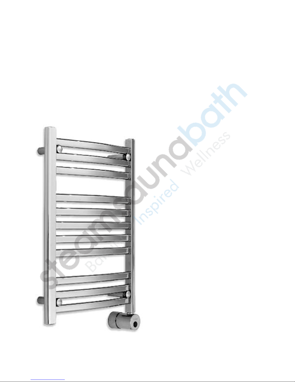
mr.steam®towelwarmers
Installation, Operation & Maintenance Instructions
_________________________________________________________________
INSTALLER:
______________________________________________________
READ THIS ENTIRE INSTRUCTION MANUAL THOROU HLY BEFORE BE IN-
NIN INSTALLATION. LEAVE THESE INSTRUCTIONS WITH HOMEOWNER.
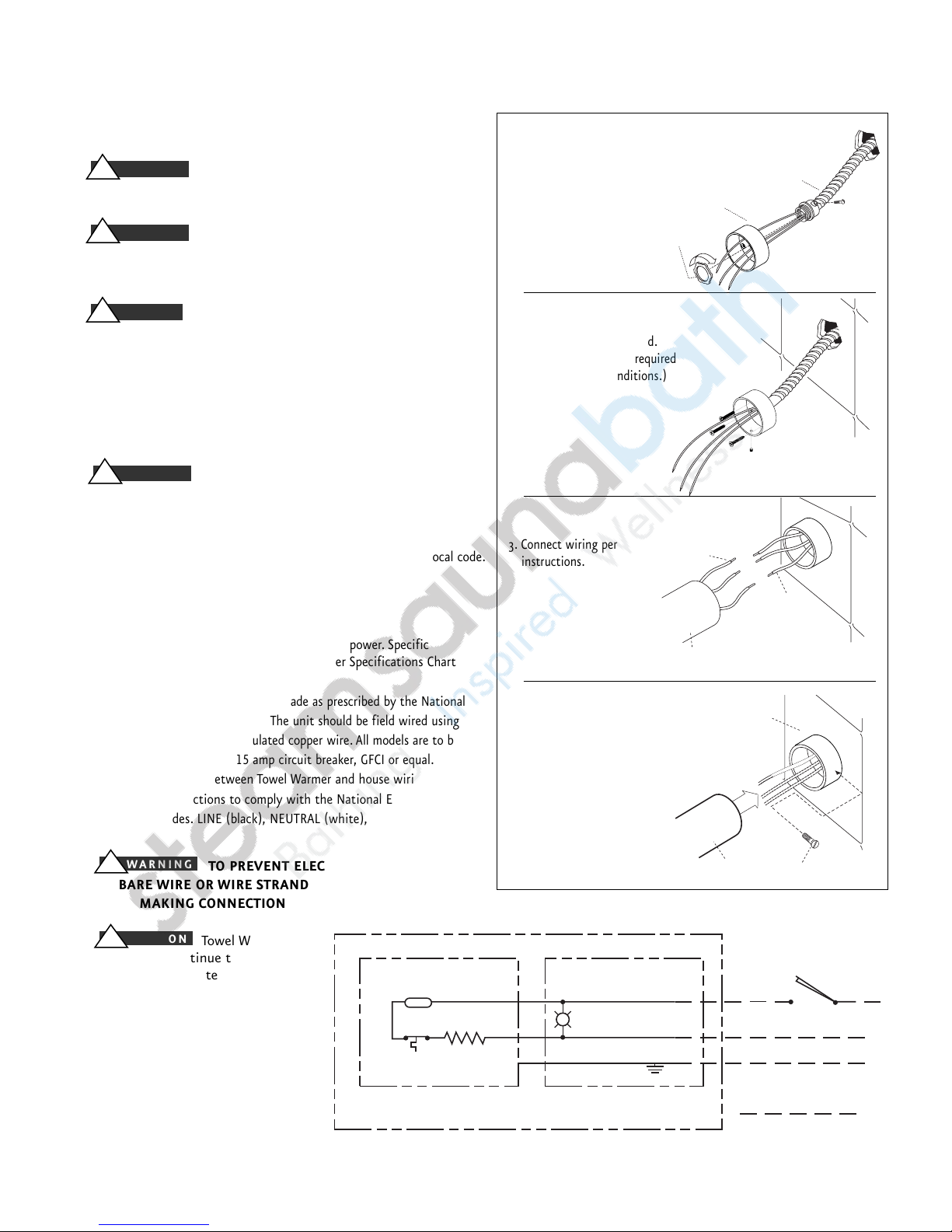
BE CERTAIN ELECTRICITY IS SHUT OFF AT MAIN
PANEL BEFORE ATTEMPTIN TO WIRE OR SERVICE THE TOWEL
WARMER. Follow instructions to make certain the Towel Warmer is
properly mounted and secured to the wall. FAILURE TO FOLLOW THESE
STEPS COULD RESULT IN HAZARDOUS CONDITIONS INCLUDIN
ELECTROCUTION.
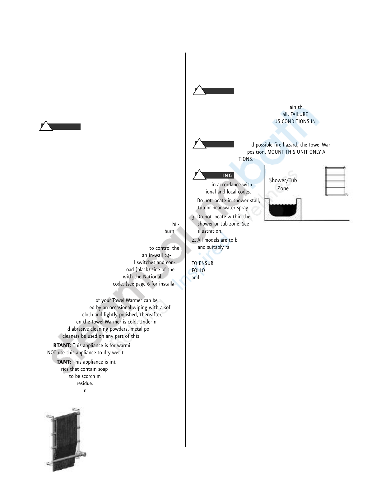
To avoid possible fire hazard, the Towel Warmer must
remain in its intended position. MOUNT THIS UNIT ONLY AS SHOWN
IN THESE INSTRUCTIONS.
1. Install in accordance with
National and local codes.
2. Do not locate in shower stall,
tub or near water spray.
3. Do not locate within the
shower or tub zone. See
illustration.
4. All models are to be protected by dedicated
and suitably rated FCI circuit breaker or equal.
TO ENSURE CORRECT OPERATION OF YOUR TOWEL WARMER, PLEASE
FOLLOW ALL INSTRUCTIONS CAREFULLY, OBSERVIN THE "CAUTION"
and “WARNIN ” NOTATIONS FOR EACH STEP.
Inspect Towel Warmer
Unpack the Towel Warmer carefully to avoid any damage or loss of any
part. When opening the box be sure that the parts are not accidentally
discarded. Towel Warmers are shipped in specially designed shipping car-
tons. The entire surface of the Towel Warmer is hand-wrapped to protect
the finish. It is your responsibility to immediately inspect for any damage.
3
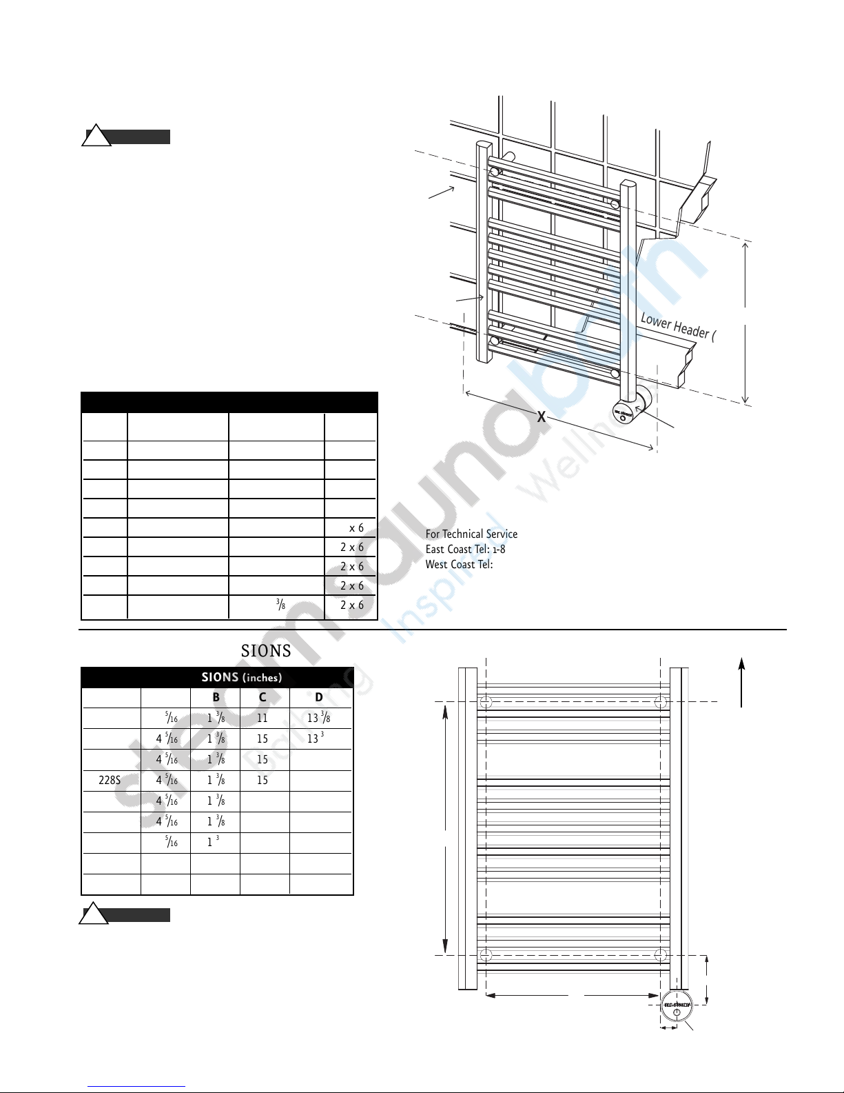
TOWEL WARMER SPECIFICATIONS
_____________________________________________________________
Model No. Dimensions (inches) Amps Volts/Phase Weight (lbs.)
WxHxD
_____________________________________________________________
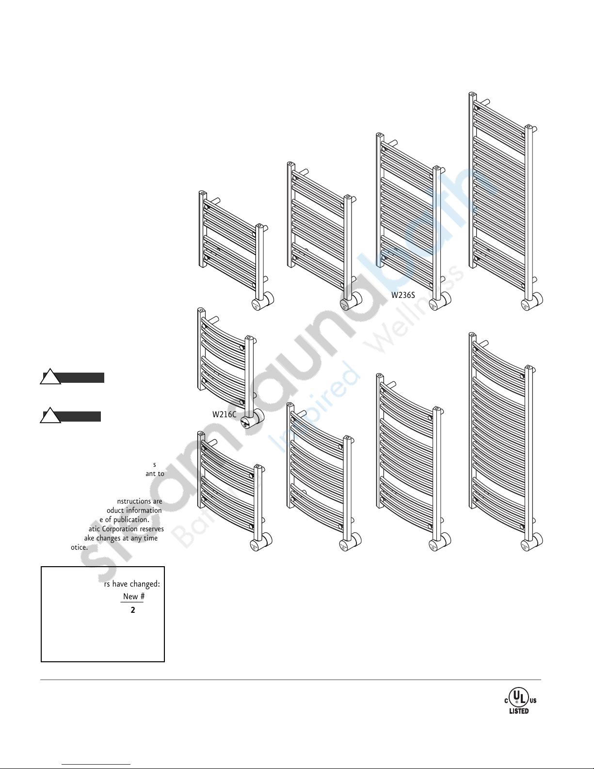
W216C 15.76 x 20 x 4.375 0.83 120/1 15
W219S 20 x 20 x 4.5 1.67 120/1 17
W219C 20 x 20 x 4.25 1.67 120/1 17
W228S 20 x 28 x 4.5 3.33 120/1 20
W228C 20 x 28 x 4.25 3.33 120/1 20
W236S 20 x 36 x 4.5 3.33 120/1 24
W236C 20 x 36 x 4.25 3.33 120/1 24
W248S 20 x 48 x 4.5 3.33 120/1 30
W248C 20 x 48 x 4.25 3.33 120/1 30
Note: Dimensions are approximate
HOMEOWNER:
________________________________________
THANK YOU for selecting Mr.Steam Towel Warmer, the perfect
addition to bathrooms, family spas, and exercise rooms within
your home. Our products have been a standard for quality and
comfort, and we are sure that you will experience continued
enjoyment from the Towel Warmer you have purchased by follow-
ing these instructions.
TOWEL WARMERS ARE HOT! The Towel
Warmer is an electrical heating appliance, intended only for
indoor residential applications and, as such, should be installed
and used with certain precautions for your safety.
1. INSTALLATION PROCEDURES FOR PERMANENTLY-WIRED WALL-
MOUNTED UNITS MUST BE ACCOMPLISHED BY QUALIFIED
PERSONNEL IN STRICT ACCORD WITH APPLICABLE NATIONAL
AND LOCAL BUILDIN AND ELECTRICAL CODES.
2. DO NOT place TOWEL WARMER units inside a shower, sauna or
steam room enclosure or any other wet location or with ele-
vated temperature because the towel warmer may be an elec-
trocution hazard.
3. CAUTION is advised when a Towel Warmer is accessible to chil-
dren because the towel warmer is hot and represents a burn
hazard.
4. A dedicated wall switch or timer should be used to control the
TOWEL WARMER unit. Contact Mr.Steam for an in-wall 24-
hour-7 day timer (PN W-103588) Note: All switches and con-
trol devices must be installed on the load (black) side of the
Towel Warmer circuit in compliance with the National
Electrical Code (NEC) and local code. (see page 6 for installa-
tion instructions)
IMPORTANT:
The finish of your Towel Warmer can be
protected and maintained by an occasional wiping with a soft,
non-abrasive, damp cloth and lightly polished, thereafter, with a
soft dry cloth when the Towel Warmer is cold. Under no circum-
stances should abrasive cleaning powders, metal polish or chlo-
rine-based cleaners be used on any part of this product.
IMPORTANT:
This appliance is for warming towels only.
DO NOT use this appliance to dry wet towels.
IMPORTANT:
This appliance is intended for towels washed in
water. Fabrics that contain soap or detergent residue may show
what appears to be scorch marks. However this may be the dis-
coloration of the residue. Mr.Steam is not responsible for discol-
oring or damage of any fabrics. Refer to the Mr.Steam towel
warmer warranty for additional terms and conditions.
For illustrative purposes only
!WARNING
!WARNING
!WARNING
!WARNING
Shower/Tub
Zone
Do not locate the
towel warmer within
the shower/tub zone
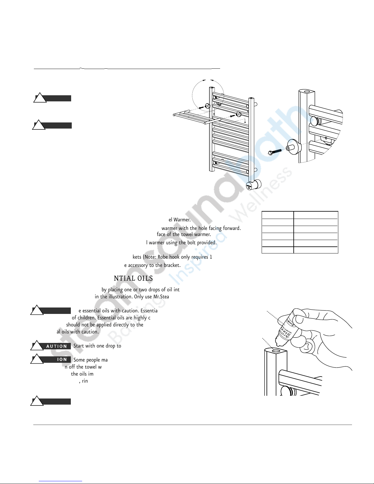
This picture shows the recommended
method of draping a towel on a towel
warmer. Ensure as much as possible of
the towel's surface is touching the towel
warmer for optimum towel warming.